Article

Experimental Study on the Impact of Smoke Exhaust Rate and Exhaust Vent Opening Mode on the Smoke Control Effect of the Point Smoke Exhaust System in an Asymmetric V-Shaped Tunnel

1
Beijing Key Laboratory of Green Built Environment and Energy Efficient Technology, Beijing University of Technology, Beijing 100124, China
2
College of Architecture and Civil Engineering, Beijing University of Technology, Beijing 100124, China
3
Beijing Metro Operation Administration Corporation Limited, Beijing 100068, China
4
Institute of Urban Safety and Environmental Science, Beijing Academy of Science and Technology, Beijing 100054, China
5
Beijing Subway Construction Facilities Maintenance Corporation Limited, Beijing 100082, China
*
Author to whom correspondence should be addressed.
Fire 2025, 8(4), 162; https://doi.org/10.3390/fire8040162
Submission received: 1 March 2025 / Revised: 7 April 2025 / Accepted: 14 April 2025 / Published: 21 April 2025

Abstract

:
Small-scale model experiments were conducted to examine the effectiveness of a point smoke exhaust system in an asymmetrical V-shaped tunnel. Using a design fire power of 20 MW as a reference, the study explored the optimal smoke exhaust rate for the point exhaust system in tunnels. Additionally, the impact of different slope combinations and various smoke vent opening configurations on the smoke control efficiency was analyzed when the fire source was positioned at the slope transition point of the V-shaped tunnel. The results indicate that an exhaust rate of approximately 140–160 m3/s is effective in controlling smoke for a 20 MW fire. In V-shaped tunnels, when three exhaust vents are symmetrically opened on both sides of the fire source, smoke diffusion on the large slope side remains uncontrolled. To address this issue, increasing the number of smoke exhaust vents on the large slope side can enhance smoke control. However, when the slope difference between the two sides of an asymmetrical V-shaped tunnel is excessively large—especially when the large side has a very high inclination—effective smoke control becomes significantly more challenging.

1. Introduction

V-shaped tunnels are commonly found in urban underground roads, as well as in cross-river and cross-sea tunnels. In the event of a fire occurring at the slope transition point of a V-shaped tunnel, the thermal pressure generated on each side of the fire source differs due to the varying slopes. This discrepancy leads to asymmetric smoke dispersion along both sides of the fire source. As the fire continues to burn, the thermal pressure difference between the two sides increases, potentially causing smoke backflow on the smaller slope side while driving smoke toward the steeper slope side. These unique smoke flow characteristics make smoke control in V-shaped tunnels more complex compared to that in other tunnel types. In urban traffic tunnels where frequent or periodic traffic congestion occurs, point exhaust systems are commonly employed for smoke control [1,2,3]. However, the impact of the distinctive smoke dispersion behavior in V-shaped tunnels on the effectiveness of point exhaust systems requires further investigation.
Previous research on point smoke exhaust systems in tunnels has primarily focused on horizontal and single-slope tunnels. Ingason and Li [4] conducted scaled modeling experiments to evaluate the smoke exhaust efficiency of point exhaust systems, concluding that double-point exhaust systems have higher efficiency than single-point systems. Vauquelin [5] et al. investigated smoke exhaust efficiency during tunnel fires using a scaled-down model and found that ceiling-mounted ducts are more effective than those positioned on the walls. Mei [6] et al. examined the smoke layer thickness and plug-holing characteristics of a multi-point exhaust system through a small-scale model. The findings indicated that at a given heat release rate (HRR), increasing the number of vents reduces both the smoke plug-holing exhaust rate and the d/H ratio (smoke layer depth to clear height). He [7] et al. used numerical simulations to analyze entrainment near vents in tunnel fires, exploring the effects of HRR and exhaust velocity. The results demonstrated that fresh air volume in the tunnel increases with both HRR and exhaust velocity. When the exhaust smoke temperature is low, the fresh air mass flow rate entering the shaft shows minimal sensitivity to HRR but is strongly influenced by the volume of exhaust smoke. Lin [8] et al. investigated the impact of slope on the performance of semi-transverse smoke control and exhaust systems using numerical simulations. The result indicated that increasing the slope reduces the time available for safe evacuation, suggesting that smoke exhaust volume should be increased by 5%, 10%, and 20% for tunnel slopes of 1%, 3%, and 5%, respectively, compared to the ASHRAE recommendations. Ying [9] et al. utilized numerical simulations to study the effects of HRR, exhaust volume, vent spacing, and total vent area on smoke propagation in a multi-point centralized exhaust system. They observed that increasing the exhaust volume reduces the maximum temperature rise, while increasing the other three factors leads to greater temperature rise. Additionally, the smoke removal efficiency improved with increased exhaust volume but declined with higher HRR, greater vent spacing, and larger vent areas. Li [10] et al. examined the longitudinal temperature distribution beneath the tunnel roof and the combined effects of multi-point exhaust systems and longitudinal ventilation. The results showed that excessive exhaust volume can lead to plug-holing, reducing the exhaust efficiency and causing a temperature drop at the vent. The longitudinal temperature decay rate near the exhaust fan is lower than that on the opposite side. Although the combination of multi-point exhaust and longitudinal ventilation effectively controls smoke, the longitudinal wind speed should not exceed 0.5 m/s. Tang [11] et al. explored the evolution of critical wind speed under the combined effects of roof-centered mechanical exhaust and longitudinal ventilation through small-scale experiments. The results showed that critical wind speed decreases with increased exhaust volume, while the critical Froude number increases at a given dimensionless HRR. Zhao [12] et al. analyzed the influence of HRR and vent settings on plug-holing using a small-scale model. The results indicated that the amount of smoke required for plug-holing increases with the HRR and aspect ratio. Additionally, increasing the vent area raises the amount of smoke required for plug-holing, but when the vent area exceeds a certain threshold, hot smoke may not fully fill the vent, causing backflow. Tao [13] et al. investigated the effects of different vent arrangements on fire characteristics and smoke exhaust efficiency using numerical simulations. The results showed that opening four vents near the fire source minimized the total smoke spread length. Across different vent arrangements, the maximum temperature first increased and then decreased with greater exhaust volume. Among the tested configurations, the four-vent setup demonstrated the highest smoke removal efficiency and maintained the temperature field within an optimal range. Jin [14] et al. analyzed the behavior of the smoke layer interface, thickness, vertical temperature distribution, and normalized shear rate in tunnels using scaled-down model tests and simulations. The results showed that lateral exhaust velocity significantly affects smoke layer stability. At lower exhaust velocities, the smoke retains its stratified state, whereas higher exhaust velocities disrupt the layering, resulting in a mixed smoke environment. In addition, the smoke characteristics of tunnel fires have been studied by Ura [15], Tanaka [16], Ingason [17], and Ho [18].
As for the design of the multi-point smoke exhaust system in tunnels, the relevant provisions in the current code are relatively general, and some provisions in different codes are inconsistent or even contradictory, such as the provisions on the smoke exhaust rate, although almost all codes recommended that the smoke exhaust rate should be related to the design fire power [1,2,3]. However, the recommended values in the Guidelines for Design of Ventilation of Highway Tunnels [1] are inconsistent with those of the same fire scale in the PIARC Report [3], and all the provisions in the current design codes are only for the horizontal tunnel fires. Whether the smoke exhaust system designed based on these provisions can effectively control smoke in V-shaped tunnels with slightly complex structures is still questionable.
The smoke flow in V-shaped tunnels is very different from that in single-slope tunnels. There are fewer studies on the smoke control efficiency of the point smoke exhaust system in V-shaped tunnels, and most of those studies are based on the numerical simulations; the results of the studies also require more model experiments for verification. In addition, the current code also lacks relevant provisions for the smoke control design of V-shaped tunnels. Based on this, this study will investigate the controversial exhaust rate of the point smoke exhaust system in a tunnel fire by small-scale model experiments, and the smoke control effect of the point exhaust system designed according to the existing codes and standards in asymmetric V-shaped tunnels will also be studied. Since most of the urban underground tunnels do not allow large vehicles to pass through, the design fire size should be about 20 MW. Taking 20 MW design fire as an example, this study will investigate the reasonable design value of the smoke exhaust rate of the point smoke exhaust system in tunnel fire and the smoke control effect of the point smoke exhaust system in the V-shaped tunnel based on the current design guide through the small-scale model experiments, so as to provide necessary technical support for effective smoke control when adopting the point smoke exhaust system in V-shaped tunnels.

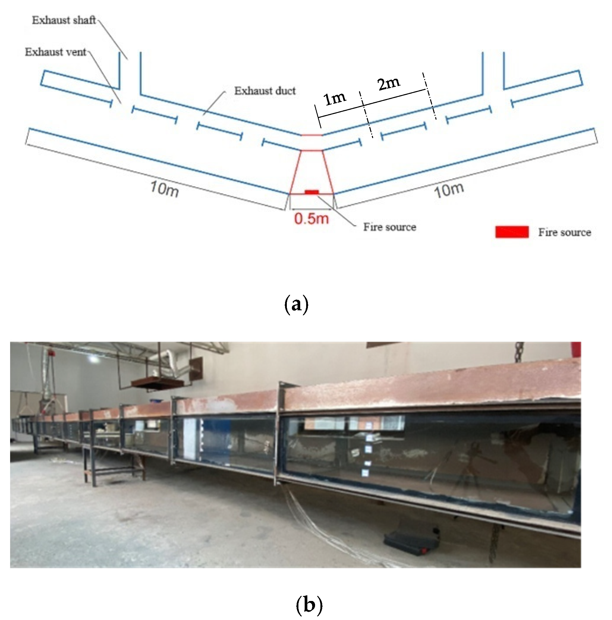
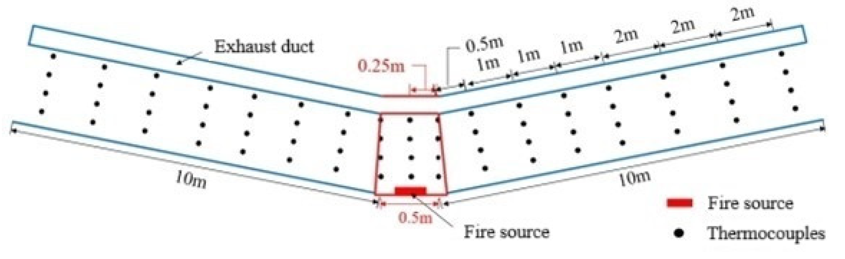
2. Experimental Setup

Using a three-lane urban underground road in Beijing as a prototype, a 1:20 scale model tunnel was developed based on Froude’s law, as illustrated in Figure 1. The scaling relationship follows the parameters outlined in Table 1 [19].
The model tunnel measures 20.5 m in length and consists of a central horizontal section flanked by two adjustable slope sections. The variable slope sections are each 10 m long, while the length of the middle horizontal section is 0.5 m. The cross-sectional dimensions of the tunnel are 0.675 m in width and 0.5 m in height. To enable slope adjustments on both sides, a lifting device with a chain mechanism is connected to the ends of the variable slope sections. By pulling the chain, the height of the tunnel ends can be adjusted, allowing for slope variations ranging from 0° to 10°. A closed space, 0.125 m in height, is separated from the tunnel roof by a partition board, forming the smoke exhaust duct for the point smoke exhaust system. Six exhaust vents are set at the lower part of the exhaust duct, and the spacing between the vents is 2.0 m; distributions of the exhaust vents are shown in Figure 1. Two exhaust shafts are positioned at the upper parts of the variable slope sections on both sides of the tunnel, located 6 m from the fire source. Each shaft is equipped with an exhaust fan, specifically a variable-frequency axial fan with a rated voltage of 220 V and an air volume flow rate of 530 m3/h. During the experiment, the exhaust rate is controlled via frequency conversion regulation.
The fire source is positioned in the middle horizontal section, as shown in Figure 1. Liquefied petroleum gas (LPG) was used as the experimental fuel, with a density of 2.35 kg/m3 and a combustion calorific value of 43.7 MJ/kg. The experimental fire burner measured 0.15 m × 0.10 m × 0.06 m (length × width × height). Since large goods vehicles (LGVs) and other heavy vehicles are prohibited from passing through urban underground tunnels, the design fire power for this study was set at 20 MW, which corresponds to 11.18 kW in the scaled-down tunnel model.
The temperature measurement and data acquisition system primarily consists of K-type thermocouples, an Agilent 34970A data acquisition/logger, and a computer. The K-type thermocouples used have a diameter of 1.5 mm and a measurement accuracy of ±1.1 °C. A total of 17 thermocouple trees are arranged along the longitudinal direction of the tunnel, with three located in the central fire section and seven positioned in each of the slope sections on both sides. The spacing between the thermocouples is illustrated in Figure 2. Each thermocouple tree contains four thermocouples, vertically spaced at 0.09 m intervals, with the lowest thermocouple positioned 0.1 m above the tunnel floor. To enhance visualization of the smoke flow, stratification, and entrainment, laser light sources with a wavelength of 530 nm are placed at the entrances on both ends of the tunnel.

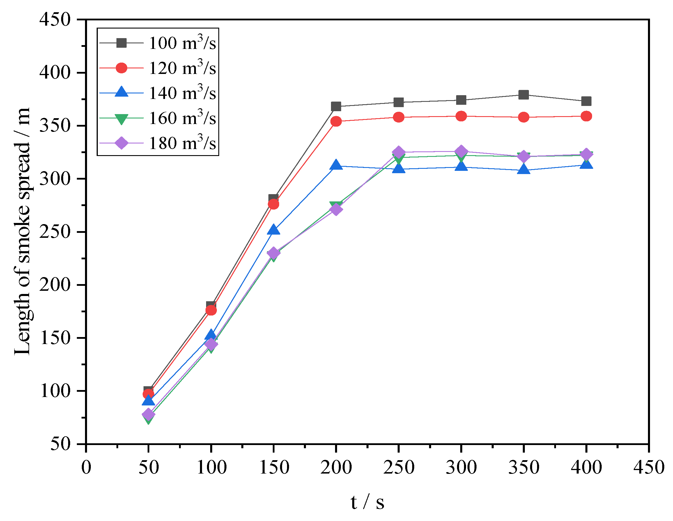
3. Study on Smoke Exhaust Rate of Point Exhaust System in Straight Tunnel

3.1. Experimental Scenarios

The longitudinal spacing of exhaust vents recommended by the “Road Tunnel Design Code” (DG/TJ08-2033-2017) [2] should be not be greater than 60 m, so a spacing distance of 40 m was adopted in this study. The vent size is 0.3 m × 0.2 m (L × W) with reference to the actual design value in an underground road in Beijing. Following the recommended exhaust rate in the present tunnel design guides, five different smoke exhaust rates are selected to study the smoke exhaust effect, as shown in Table 2. Three exhaust vents are activated on either sides of the fire source. The parameters in Table 2 have been converted to the corresponding full-scale values by the relative expressions in Table 1 for the applicability of the results for practical engineering purposes. In the scale model experiment, the spacing between exhaust vents is 2 m, and smoke exhaust rates are 0.056 m3/s, 0.067 m3/s, 0.078 m3/s, 0.089 m3/s, and 0.100 m3/s, respectively.

3.2. Results and Discussion

Figure 3 illustrates the local smoke flow behavior at the first exhaust vent on the right side of the fire source under different smoke exhaust rates. As shown in the figure, when the exhaust rate is 100 m3/s or 120 m3/s, the insufficient smoke extraction leads to rapid smoke spread beneath the exhaust duct, causing smoke descent and resulting in a low smoke layer height of approximately 2 m. As the exhaust rate increases, the smoke layer height gradually rises, and the horizontal spread of smoke within the tunnel decreases. However, when the exhaust rate reaches 160 m3/s, a noticeable depression forms at the exhaust vent, as shown in Figure 3d, indicating that cold air has infiltrated the exhaust duct through the vent. This air intrusion reduces the exhaust efficiency and increases the smoke spread distance. When the exhaust rate exceeds 180 m3/s, plug-holing fully occurs, significantly diminishing the vent’s smoke extraction capability, as a large volume of air enters the exhaust duct through the first exhaust vent.
Figure 4 shows the spread distance of smoke under different exhaust rates. It can also be seen from the figure that when the exhaust volume is 100 m3/s or 120 m3/s, due to the low exhaust rate, the exhaust system cannot control the smoke within the range of about 300 m. When the exhaust rate exceeds 160 m3/s, due to the local rate of the vent being too large, the smoke layer is destroyed, the air at the lower side of the smoke layer enters the exhaust duct, and the plug-holing phenomenon begins to appear at the exhaust vent. The longitudinal inertial force of the smoke does not decrease, the smoke will continue to spread to both sides to around 330 m, and the thickness of the smoke layer will gradually become thicker and thicker; this will be a threat to the evacuation of personnel.
Based on the analysis of the above experimental results, when a fire of 20 MW occurs in a one-way three-lane tunnel, the smoke exhaust rate should be in the range of 140~160 m3/s. Under this exhaust rate, the smoke spread distance can be controlled within the range of 300 m, the height of the smoke layer can be maintained at more than 3.0 m, and the smoke exhaust efficiency is relatively high, which can ensure the safe evacuation of personnel.

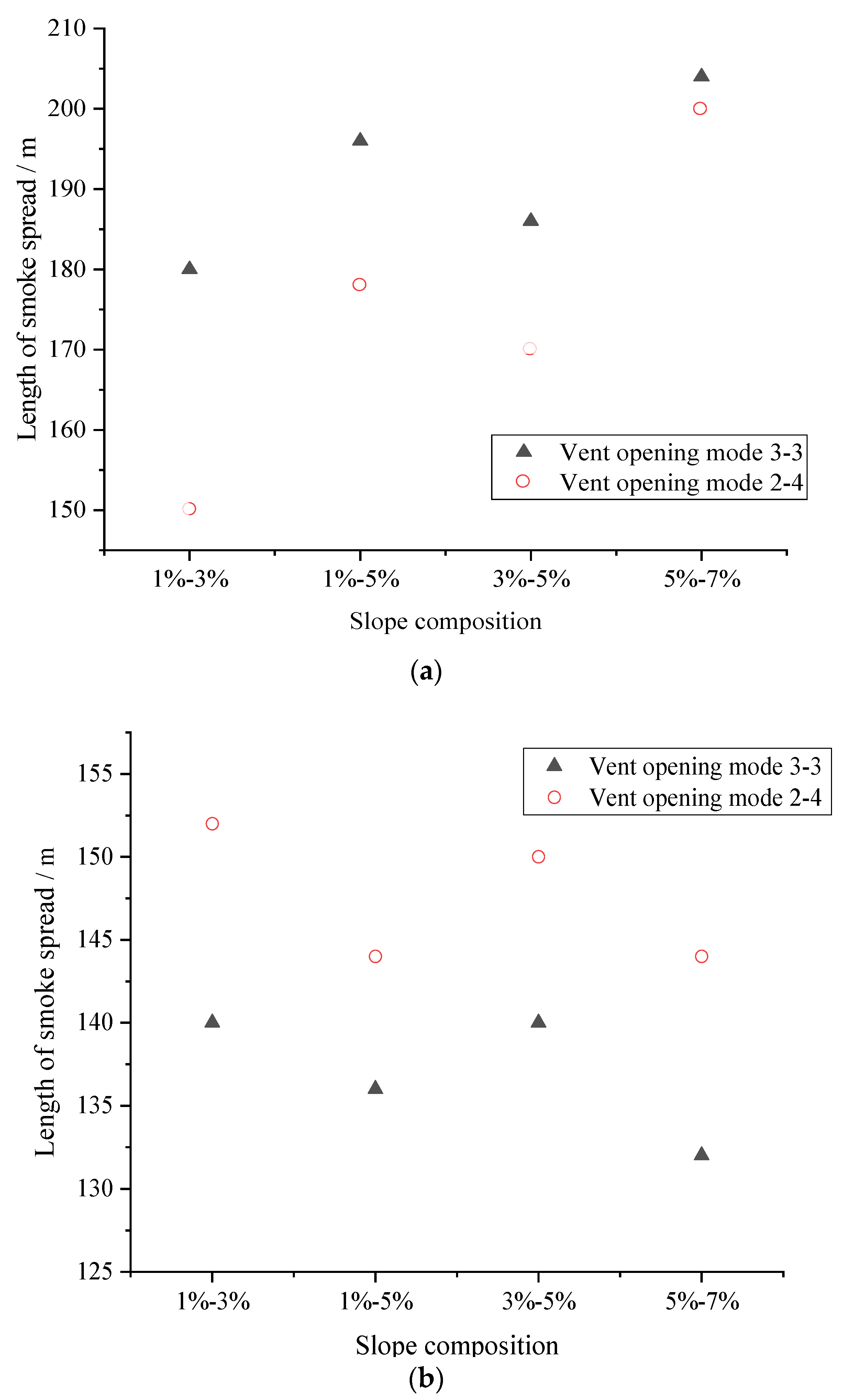
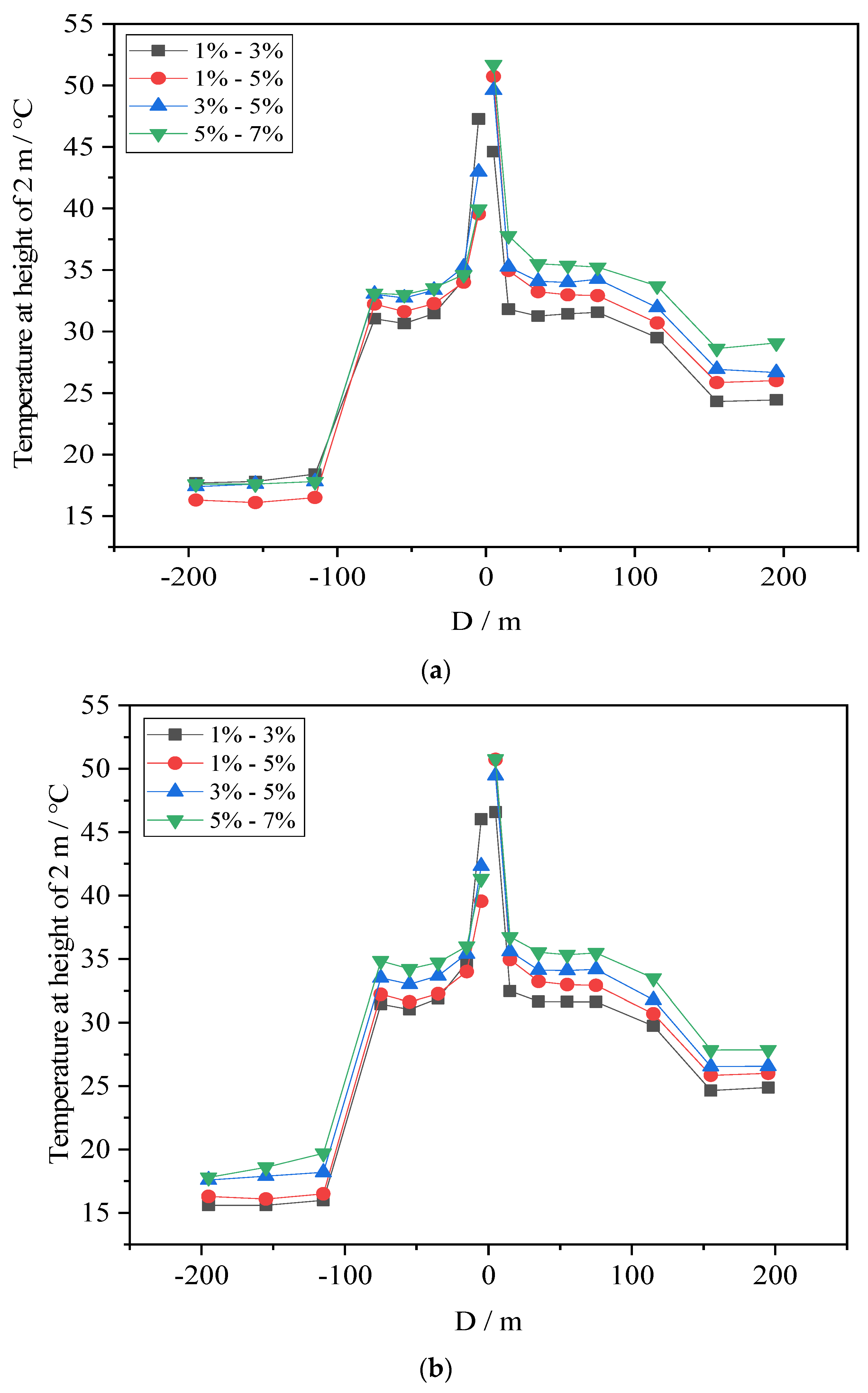
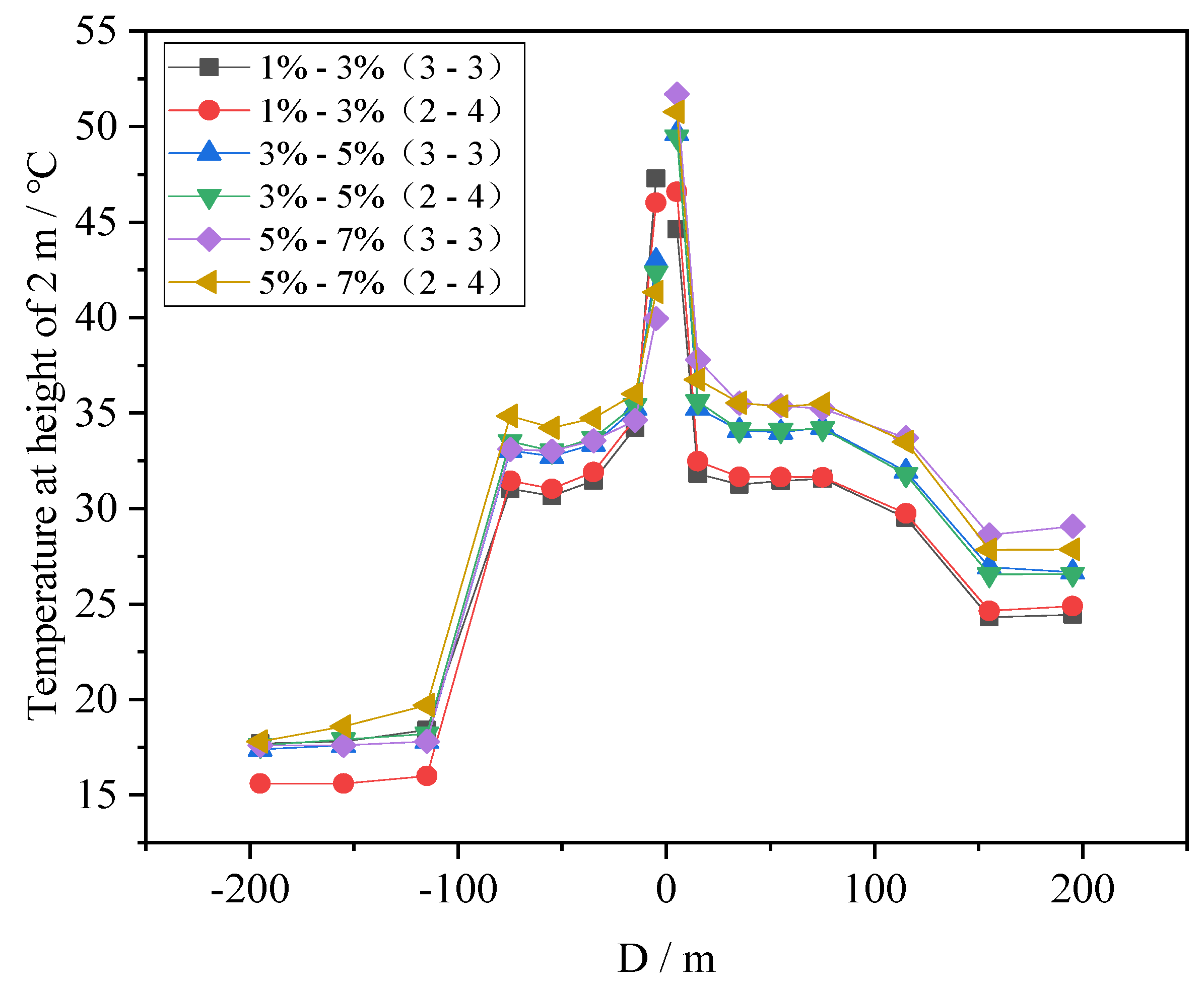
4. The Effect of the Vent Opening Mode on the Smoke Control Effect of the Point Exhaust System in an Asymmetric V-Shaped Tunnel

4.1. Experimental Scenarios

Following the “Code for design of urban underground road engineering” (CJJ 221-2015) [20] for the limitation of the longitudinal slope, the slope of both sides of the V-shaped slope is set to different slope combinations of 1%, 3%, 5%, and 7% in the experiment,; the smoke exhaust rate is set to 140 m3/s; the opening area of a single exhaust vent is 6 m2; and six exhaust vents are activated for the smoke exhaust. The spacing between the vents is 40 m. For the V-shaped tunnels with significant slope differences between the two sides, as smoke flows towards the side with large gradient, this study aims to investigate the impact of different opening modes on the smoke control effect by changing the different opening quantities of the upstream and downstream smoke exhaust vents of the fire source. The experimental scenarios are set as shown in Table 3, where the opening mode 3-3 represents that three exhaust vents are opened at the upstream and three exhaust vents are opened at the downstream of the fire source; 2-4 means that two exhaust vents are opened at the small slope side (upstream of the fire source), and four vents are opened at the large slope side (downstream of the fire source).

4.2. Results and Discussion

Figure 5 illustrates the smoke spread distances on both sides of the fire source under different slope combinations. As shown in the figure, when the slope on the small slope side remains constant, increasing the slope of the large side reduces the smoke spread distance on that side. Conversely, when the slope of the steeper side is fixed, an increase in the slope of the small slope side leads to an extended smoke spread distance on that side. Additionally, when the exhaust vent opening configuration is changed from 3-3 to 2-2, the smoke spread distance on the steeper slope side decreases, while the spread distance on the smaller slope side increases. However, the overall smoke spread distance within the tunnel is reduced, leading to improved smoke exhaust efficiency. This is because the smoke spread is affected by the longitudinal thermal driving force and the inertial force of the smoke exhaust in the vertical direction. As the spread distance increases, the resistance loss gradually increases, resulting in differences in the local exhaust speeds of each exhaust vent. The local exhaust speed of the vent closest to the fire source is the smallest, and the exhaust inertia force is smaller than the thermal driving force, so the smoke spread speed is larger. When the thermal driving force is greater than or equal to the vertical inertial force, smoke spread stops. With the increase in the number of smoke exhaust vents at the large slope side, the influence of exhaust inertia force on smoke diffusion increases, and the smoke diffusion distance decreases at the large slope side. However, with the increase in the slope of the large slope side, the thermal driving force increases, resulting in the thermal driving force of smoke diffusion being significantly greater than the exhaust inertia force and the smoke control effect declining.
Compared with the horizontal tunnel, the “chimney effect” of the V-shaped tunnel makes the smoke diffusion speed greater than that of the horizontal tunnel, and the smoke spread distance also increases significantly. Meanwhile, as the slope increases, the thickness of the smoke layer correspondingly grows. When a slope difference exists between the two sides of the fire source, thermal pressure competition arises between the upstream and downstream regions, making the smoke flow behavior more complex.
Figure 6 shows the temperature distribution at the height of 2 m above the tunnel floor under different exhaust vent opening modes. From Figure 6a, it can be seen that the temperature at the height of 2 m also increases with the increase in the slope at the large slope side, while the temperature distribution at the small slope side is less affected. When the opening mode is changed, the temperature at the height of 2 m increases on the small slope side, but little changes can be found on the large slope side.
Figure 7 shows the temperature distribution at the height of 2 m for different slope compositions. It can be seen from Figure 7 that there is not much change in the temperature at 2 m height when changing the vent opening mode for the same slope composition. The temperature at 2 m height at the large slope side increases with the increase in the slope, while the temperature distribution on the small slope side is less affected. This is due to the fact that the smoke exhaust system cannot remove the high-temperature smoke in time when the slope increases, indicating that the ability of the smoke exhaust system to control the spread of smoke decreases when the slope increases.
Figure 8 illustrates the smoke spread on the steeper slope side under different slope combinations. As shown in the figure, when the slope difference between the two sides at the slope transition point reaches 4%, the smoke layer nearly fills the tunnel cross-section on the large slope side, creating a complex smoke environment that poses a significant threat to safe evacuation. When the slope difference is 2%, the thickness of the smoke layer increases as the slope of the steeper side rises, which also endangers personnel evacuation.

5. Conclusions

For the 20 MW design fire, this study investigated the optimal smoke exhaust rate for the point smoke exhaust system in tunnels, as well as the smoke control performance of the system in a V-shaped tunnel under different exhaust vent opening configurations. The following conclusions were drawn:
(1) For a horizontal tunnel, the optimal smoke exhaust rate for the point smoke exhaust system is approximately 140 m3/s to 160 m3/s. At this rate, smoke is contained within a 300 m range on both sides of the fire source, and the smoke layer height remains adequate for safe personnel evacuation. Moreover, plug-holing does not occur at this exhaust rate.
(2) In V-shaped tunnels, when the same number of exhaust vents are opened on both sides of the fire source, this configuration fails to control smoke diffusion on the large slope side. It is recommended to increase the number of smoke exhaust vents on the large side to enhance smoke control.
(3) When the slope difference between the two sides of the V-shaped tunnel is large—especially when the slope on the large side exceeds 5%—controlling smoke diffusion on the large side becomes challenging, and a clear smoke layer is unlikely to form. Additional smoke control measures should be considered to manage smoke diffusion effectively.

Author Contributions

Conceptualization, J.L. and Y.L.; methodology, Y.Q., H.Z. and J.L.; formal analysis, Y.Q., H.Z. and X.L.; Validation, D.L., S.H. and Z.W.; writing—original draft preparation, Y.Q. and J.L.; writing—review and editing, J.L. and Y.L.; funding acquisition, J.L. All authors have read and agreed to the published version of the manuscript.

Funding

This research was funded by the Beijing Natural Science Foundation (Grant No. 8222002).

Institutional Review Board Statement

Not applicable.

Informed Consent Statement

Not applicable.

Data Availability Statement

The data presented in this study are available on request from the corresponding author.

Conflicts of Interest

Authors Xiushan Lin and Shiran Hou were employed by the company Beijing Metro Operation Administration Corporation Limited. Author Zheng Wang was employed by the company Beijing Subway Construction Facilities Maintenance Corporation Limited. The remaining authors declare that the research was conducted in the absence of any commercial or financial relationships that could be construed as a potential conflict of interest.

References

  1. JTG/T D70/2-02-2014; Guidelines for Design of Ventilation of Highway Tunnels. People’s Communications Publishing House Co., Ltd.: Beijing, China, 2014. (In Chinese)
  2. DG/TJ08-2033-2017; Road Tunnel Design Code. Tongji University Press: Shanghai, China, 2017.
  3. PIARC Technical Committee on Road Tunnels. Fire and Smoke Control in Road Tunnels; World Road Association: Paris, France, 1999. [Google Scholar]
  4. Ingason, H.; Li, Y. Model scale tunnel fire tests with point extraction ventilation. J. Fire Prot. Eng.‌‌ 2011, 21, 5–36. [Google Scholar] [CrossRef]
  5. Vauquelin, O.; Megret, O. Smoke extraction experiments in case of fire in a tunnel. Fire Saf. J. 2002, 37, 525–533. [Google Scholar] [CrossRef]
  6. Mei, F.; Tang, F.; Ling, X.; Yu, J. Evolution characteristics of fire smoke layer thickness in a mechanical ventilation tunnel with multiple point extraction. Appl. Therm. Eng. 2017, 111, 248–256. [Google Scholar] [CrossRef]
  7. He, L.; Xu, Z.; Chen, H.; Liu, Q.; Wang, Y.; Zhou, Y. Analysis of entrainment phenomenon near mechanical exhaust vent and a prediction model for smoke temperature in tunnel fire. Tunn. Undergr. Space Technol. 2018, 80, 143–150. [Google Scholar] [CrossRef]
  8. Lin, P.; Lo, S.M.; Li, T. Numerical study on the impact of gradient on semi-transverse smoke control system in tunnel. Tunn. Undergr. Space Technol. 2014, 44, 68–79. [Google Scholar] [CrossRef]
  9. Ying, H.; Jiao, W.; Xu, Z.; Zhao, J.; Yu, Z. Study on smoke spreading behavior under multi-point centralized smoke extraction in tunnel fires. Case Stud. Therm. Eng. 2025, 66, 105731. [Google Scholar] [CrossRef]
  10. Li, J.; Zeng, Y.; Tao, L.; Liu, Z.; Li, B. Experimental study on temperature decay and smoke control in tunnel fires with combination of multi-point smoke exhaust and longitudinal ventilation. Int. J. Therm. Sci. 2023, 183, 107847. [Google Scholar] [CrossRef]
  11. Tang, F.; He, Q.; Mei, F.; Wang, Q.; Zhang, H. Effect of ceiling centralized mechanical smoke exhaust on the critical velocity that inhibits the reverse flow of thermal plume in a longitudinal ventilated tunnel. Tunn. Undergr. Space Technol. 2018, 82, 191–198. [Google Scholar] [CrossRef]
  12. Zhao, P.; Yuan, Z.; Yu, N.; Liang, C. Effect of heat release rate and exhaust vent settings on the occurrence of plug-holing during tunnel fires with two-point extraction ventilation. Tunn. Undergr. Space Technol. 2020, 106, 103617. [Google Scholar] [CrossRef]
  13. Tao, L.; Zeng, Y. Effect of different smoke vent layouts on smoke and temperature distribution in single-side multi-point exhaust tunnel fires: A case study. Fire 2022, 5, 28. [Google Scholar] [CrossRef]
  14. Jin, J.; Jiang, X. A study of the characteristics of smoke stratification in lateral point smoke exhaust tunnel. Fire Saf. J. 2023, 140, 103833. [Google Scholar] [CrossRef]
  15. Ura, F.; Kawabata, N.; Tanaka, F. Characteristics of smoke extraction by natural ventilation during a fire in a shallow urban road tunnel with roof openings. Fire Saf. J. 2014, 67, 96–106. [Google Scholar] [CrossRef]
  16. Tanaka, F.; Kawabata, N.; Ura, F. Smoke spreading characteristics during a fire in a shallow urban road tunnel with roof openings under a longitudinal external wind blowing. Fire Saf. J. 2017, 90, 156–168. [Google Scholar] [CrossRef]
  17. Ingason, H.; Anders, L.; Li, Y. Model of ventilation flows during large tunnel fires. Tunn. Undergr. Space Technol. 2012, 30, 64–73. [Google Scholar] [CrossRef]
  18. Ho, Y.T.; Kawabata, N.; Seike, M.; Hasegawa, M.; Chien, S.W.; Shen, T.S. Scale model experiments and simulations to investigate the effect of vehicular blockage on backlayering length in tunnel fire. Buildings 2022, 12, 1006. [Google Scholar] [CrossRef]
  19. NFPA 92; Standard for Smoke Control System. National Fire Protection Association: Quincy, MA, USA, 2018.
  20. CJJ 221-2015; Code for design of urban underground road engineering. China Architecture & Building Press: Beijing, China, 2015.
Figure 1. Sketch of the small-scale model tunnel. (a) Sketch of the small-scale model tunnel; (b) The small-scale model tunnel.
Fire 08 00162 g001
Figure 2. Distribution of the thermocouple trees.
Fire 08 00162 g002
Figure 3. Local smoke flow of the first exhaust vent at the right side of the fire source under different smoke exhaust rates. (a) Exhaust rate of 100 m3/s; (b) Exhaust rate of 120 m3/s; (c) Exhaust rate of 140 m3/s; (d) Exhaust rate of 160 m3/s; (e) Exhaust rate of 180 m3/s.
Fire 08 00162 g003aFire 08 00162 g003b
Figure 4. Variation of smoke spread distance with time.
Fire 08 00162 g004
Figure 5. Smoke spread distance under different exhaust vent opening modes: (a) Large slope side; (b) Small slope side.
Fire 08 00162 g005
Figure 6. Longitudinal temperature distribution at height of 2 m under different smoke exhaust vent opening modes: (a) Exhaust vent opening mode 3-3; (b) Vent opening mode 2-4.
Fire 08 00162 g006
Figure 7. Longitudinal temperature distribution at height of 2 m under different slope compositions.
Fire 08 00162 g007
Figure 8. Smoke spread at the large slope side with different slope compositions. (a) 1%-3%, (b) 1%-5%, (c) 3%-5%, (d) 5%-7%.
Fire 08 00162 g008aFire 08 00162 g008b
Table 1. Scaling expressions.
Characteristic RelationshipExpression
Position or length x m / x f = L m / L f
Temperature T m / T f = 1
Velocity v m / v f = L m / L f 1 / 2
Total heat release rate Q m / Q f = L m / L f 5 / 2
Volumetric flow rate V m / V f = L m / L f 5 / 2
where subscripts: f = full scale; m = small-scale model.
Table 2. Experimental scenarios on smoke exhaust rate.
Number of ScenariosSpacing Between Vents/mVent Area/m2Number of Vent OpeningsSmoke Exhaust Rate/m3/s
14066100
2120
3140
4160
5180
Table 3. Experimental scenarios.
Number of ScenariosExhaust Rate
/m3/s
Exhaust Vent Area/m2Exhaust Vent Opening ModeSlope Composition
1140 63-31%-3%
22-41%-3%
33-31%-5%
42-41%-5%
53-33%-5%
62-43%-5%
73-35%-7%
82-45%-7%
Disclaimer/Publisher’s Note: The statements, opinions and data contained in all publications are solely those of the individual author(s) and contributor(s) and not of MDPI and/or the editor(s). MDPI and/or the editor(s) disclaim responsibility for any injury to people or property resulting from any ideas, methods, instructions or products referred to in the content.

