Abstract
To mitigate explosion hazards arising from hydrogen leakage and subsequent mixing with air, the injection of inert gases can substantially diminish explosion risk. However, prevailing research has predominantly characterized inert gas dilution effects on explosion behavior under quiescent conditions, largely neglecting the turbulence-mediated explosion enhancement inherent to dynamic mixing scenarios. A comprehensive investigation was conducted on the combustion behavior of 30%, 50%, and 70% H2-air mixtures subjected to jet-induced (CO2, N2, He) turbulent flow, incorporating quantitative characterization of both the evolving turbulent flow field and flame front dynamics. Research has demonstrated that both an increased H2 concentration and a higher jet medium molecular weight increase the turbulence intensity: the former reduces the mixture molecular weight to accelerate diffusion, whereas the latter results in more pronounced disturbances from heavier molecules. In addition, when CO2 serves as the jet medium, a critical flame radius threshold emerges where the flame propagation velocity decreases below this threshold because CO2 dilution effects suppress combustion, whereas exceeding it leads to enhanced propagation as initial disturbances become the dominant factor. Furthermore, at reduced H2 concentrations (30–50%), flow disturbances induce flame front wrinkling while preserving the spherical geometry; conversely, at 70% H2, substantial flame deformation occurs because of the inverse correlation between the laminar burning velocity and flame instability governing this transition. Through systematic quantitative analysis, this study elucidates the evolutionary patterns of both turbulent fields and flame fronts, offering groundbreaking perspectives on H2 combustion and explosion propagation in turbulent environments.
1. Introduction
Owing to its high availability and compatibility with conventional fuels [,,], hydrogen plays a pivotal role in achieving carbon neutrality goals. However, its use is associated with considerable safety risks owing to its inherent attributes such as low ignition energy, broad flammability limits, and high combustion velocity [,,,,]. The inherent instability of H2 flames leads to wrinkled cellular structures and flame fronts during propagation [,,,], resulting in dramatic acceleration of the flame speed [,,]. External turbulence, whether from obstacles or flow disturbances, exacerbates this instability through enhanced flame wrinkling and increased reaction surface area [,]. These mechanisms significantly increase the combustion rates and the explosion severity [,]. Understanding jet-induced turbulence effects on flame propagation dynamics is therefore critical for safe H2 applications.
Multiple turbulence generation systems have been developed for closed experimental environments, with principal methods categorized as intake jets, rotational disturbances, and orifice plate translations. A significant body of research has focused on the explosion characteristics under turbulent flow conditions. Wang et al. [] investigated the effect of the blockage ratio on the turbulence intensity and qualitatively assessed its impact on H2-air mixture explosions. Su et al. [] modulated the turbulence intensity through jet pressure variations to obtain the explosive power of CH4/C2H4/air mixtures. By altering the ignition energy to indirectly vary the initial turbulence intensity, Kun et al. [] examined its effects on laminar combustion velocity and explosion characteristics of CH4 across a range of concentrations. Cai et al. [] qualitatively controlled the turbulence intensity by varying the ignition-position jet outlet velocity when the liquefied petroleum gas/dimethyl ether clean mixed fuel explosion behavior was studied. Chang et al. [,] identified the molecular weight of the jet medium as a critical factor governing turbulent energy generation, enabling turbulence modulation through medium selection. Dong et al. [] also qualitatively varied the turbulence intensity by adjusting the fan speed. The predominant research paradigm involves qualitative turbulence modification through jet pressure adjustment [,,], jet outlet velocity control [,,,,], fan speed regulation [,,], and blockage ratio variation [,,], without conducting in-depth investigations into the turbulent flow field state under these influences. Most turbulence studies focus on isotropic flow fields, with limited quantitative analysis of local parameters.
Under turbulent combustion conditions, flame dynamics are governed not only by intrinsic hydrodynamic instabilities but also by multiscale turbulent flow structures. The synergistic interaction between these mechanisms leads to complex flame topologies during propagation and evolution [,,,,]. In terms of flame morphology, the effects of preferential diffusion on flame propagation and front structure in lean H2-CO-air mixtures with high H2 ratios were examined by Dinesh et al. [] via numerical simulations at elevated initial pressures. The results indicate that under high-pressure and low-turbulence conditions, thermal diffusion instability is identified as the primary mechanism governing the formation of honeycomb-shaped flame structures in lean H2-CO-air mixtures. Conversely, under high-pressure, high-turbulence conditions, the thermal diffusion effects become destabilized, and turbulence emerges as the primary governing factor in flame morphology. Wang et al. [] captured the instantaneous flame surface structure of CO-H2-CO2-air mixtures under high-pressure turbulent conditions and compared it with the flame structure of CH4-air premixed mixtures. The results revealed that, compared with the CH4-air premixed flame, the synthetic gas flame exhibited more folds on the front and numerous small cellular structures derived from the flame front. The impact of turbulence intensity on the propagation characteristics of CH4/air flames was examined by Sun et al. [], documenting flame evolution across various operating conditions. However, their analysis of flame morphology and cellular structures has remained largely qualitative. Only a limited number of studies have performed quantitative analyses on flame structure. Kaminski et al. [] employed PLIF imaging technology to obtain real-time OH radical concentration fields during turbulent CH4-air premixed flame explosions. They quantified key parameters such as the flame front length, burned gas area, surface-to-volume ratio, and curvature, along with their statistical fluctuations. Haq et al. [] employed OH-PLIF to capture the two-dimensional flame structures of C9H2O-CH4-air premixed mixtures under both laminar and turbulent conditions, with varying initial pressures and equivalence ratios. Their experimental results revealed that turbulent iso-octane–air flames at an equivalence ratio of 1.4 develop localized quenching zones along the flame front. Notably, the mean separation distance between these quenching zones increased with increasing turbulence intensity.
Prior research has focused predominantly on qualitative investigations of flame surface morphology and wrinkling characteristics during combustion under static conditions. This research combines experimental and numerical simulations to investigate the influence of critical parameters such as jet medium composition and H2 concentration on turbulent flow field properties. High-speed and schlieren imaging techniques are utilized to capture flame dynamics, facilitating a quantified assessment of turbulent flow field effects on flame structure evolution.
2. Methodology
2.1. Experimental System
As shown in Figure 1a, the experiment was conducted using a setup consisting of a 20-L spherical chamber, a fluidic jet generation apparatus, a synchronized trigger control system, an electrical ignition system, and a data acquisition unit. The experimental system is detailed in our prior work [], Table 1 summarizes the types and key parameters of the experimental setup employed. Prior to experimental initiation, the gas tightness of the detection system was validated via a 20-min pressure-holding test. The jet tank was pressurized with inert gas to the predetermined 500 kPa for turbulent flow generation, whereas the 20-L spherical chamber was conditioned via sequential evacuation and Dalton’s law-compliant gas mixing to attain the specified fuel–air mixtures. As illustrated in Figure 1b, the jet apparatus comprises a 2.5 L high-pressure reservoir, a solenoid valve, a check valve, and the jet pipe. The synchronous trigger control system was programmed with the following parameters: jet duration of 100 ms, ignition delay time of 50 ms, and ignition duration of 50 ms. The specific timing sequence is illustrated in Figure 1c. Following a 10-min equilibration period within the combustion vessel, the igniter was activated to generate an electric spark. Simultaneously, the control system was initiated to acquire pressure data from two sensors mounted on the inner wall and to synchronously capture flame images via a high-speed camera. Upon experimental termination, the 20-L spherical vessel underwent a comprehensive cleaning protocol involving evacuation and triple air flushing to eliminate residual gases, thereby preventing potential contamination of subsequent experimental results.
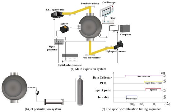
Figure 1.
Schematic representation of the experimental apparatus.

Table 1.
Relevant types or parameters for some of the apparatus.
Following jet injection, the combustion regime within the 20-L spherical vessel transitions from laminar to turbulent. In this study, the turbulence intensity is employed to characterize the turbulence degree of the jet flow. It is defined as the ratio of the root-mean-square of the turbulent fluctuation velocity to the magnitude of the local time-averaged velocity, as given by Equation (1). The flame propagation velocity serves as a fundamental parameter characterizing flame dynamics, making accurate measurement under these disturbed conditions critical. When the flame front demonstrates high structural stability, the imposed jet flow primarily induces localized modifications to the front morphology, such as wrinkles or cellular formations. However, the global flame front maintains an approximately spherical geometry during the entire propagation process. Under these conditions, we can evaluate the turbulent flame speed via a methodology analogous to laminar flame speed determination, as expressed in Equation (4).
where denotes the root-mean-square of the turbulent velocity fluctuations, is the magnitude of the local mean velocity. The fluctuating velocity components in the three coordinate directions are , while and are the time-averaged velocity components in their respective coordinate directions.
where ST is the turbulent flame propagation velocity, in m/s; Ra is the mean effective flame radius.
The jet-induced flow field within a combustion chamber exhibits significant anisotropy because the jet orifice is positioned on the unilateral horizontal sidewall. Throughout the flame propagation process, the flame centroid exhibits dynamic spatial migration, a behavior primarily controlled by unidirectional horizontal jet flow. Using MATLAB R2024a-based image processing techniques for flame contour extraction, the flame centroid is mathematically defined as (x0, y0), and the spatial coordinates of the flame front are denoted as (xi, yi). The local radius Ri, corresponding to specific angular positions θi in the polar coordinate system, can be quantitatively determined via the following equation:
Upon ignition, the flame propagates radially outward from the central ignition source, exhibiting characteristic cellular structures and progressive wrinkling because of the coupled effects of initial flow disturbances and intrinsic flame front hydrodynamic instabilities. To systematically quantify these flame front dynamics, we employ a coordinate transformation methodology that converts the polar representation to a Cartesian coordinate system, as detailed in Figure 2a, enabling decomposition of the local flame radius Ri into the mean effective flame radius Ra and the fluctuating component Ri′ components through the relation Ri = Ra + Ri′. As shown in Figure 2b, quantitative analysis reveals a stochastic spatial distribution of flame front wrinkling without discernible periodicity, featuring random occurrences of both convex and concave topologies, along with significant variations in the area bounded by the flame front and effective radius. Further characterization through cumulative probability distribution analysis of the pulsation radii, as illustrated in Figure 2c, reveals that the pulsation radii exhibit a concentrated distribution at approximately 0 mm, with their relative proportion decreasing as the pulsation amplitude increases.
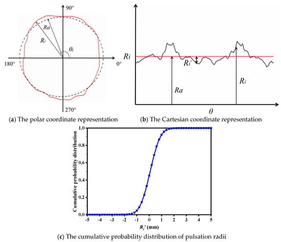
Figure 2.
Measurement of the flame pulsation radius and its cumulative probability distribution.
Wavelet analysis is based on multiresolution analysis (MRA). MRA is a mathematical framework initially developed by Mallat for solving image processing problems. This method can decompose image information at different scales to obtain multiscale results and extract key features from them. The wavelet transform was first proposed by French engineer Morlet in 1974 and has since played a crucial role in signal analysis and image processing applications.
The continuous wavelet transform is defined as:
where represents the mother wavelet; b denotes the scaling parameter.
Wavelet decomposition enables multiscale analysis of flame front dynamics by separating the signal into A and D, which represent low-frequency and high-frequency components, respectively. The approximation coefficients capture the slowly varying, energy-dominant aspects of the flame front that define its global morphology, whereas the detail coefficients encode high-frequency features containing localized information about abrupt changes and sharp variations. The decomposition process is illustrated in Figure 3a. Initially, the image contour information is decomposed into two parts through wavelet decomposition: the low-frequency information A1 and the high-frequency information D1. On the basis of the first-scale decomposition, the low-frequency information A1 is subsequently decomposed into two parts: the low-frequency information A2 and the high-frequency information D2. This process is repeated iteratively until the fifth scale of decomposition is achieved, resulting in low-frequency information A5 and high-frequency information D5. Figure 3b presents a decomposition diagram of the flame front disturbance information at different scales. As shown in the diagram, the magnitude of flame front fluctuations increases progressively with the decomposition scale number. Notably, D1 clearly captures the abrupt position of the original waveform S, whereas A5 reflects the general variation trend of the flame front. Table 2 presents the relevant parameters obtained from the decomposition of the flame front perturbations.
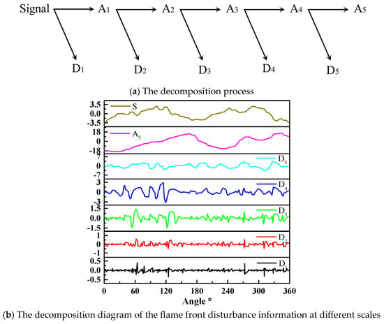
Figure 3.
Decomposition process of the flame front disturbance information at different scales.

Table 2.
Parameters associated with the flame front disturbance decomposition diagram.
2.2. Simulation Method
This investigation establishes a computational fluid dynamics (CFD) framework for simulating turbulent jets within a 20-L spherical vessel, implemented through ANSYS FLUENT 2024R1 with rigorous adherence to fundamental fluid dynamics principles. Simulating turbulent flow involves numerically solving the Navier–Stokes (N–S) equations to extract key physical parameters governing jet dynamics. The numerical simulation is based on the Reynolds–averaged Navier–Stokes (RANS) formalism, incorporating the standard k–ε turbulence closure model. The coupled equation system is resolved numerically via a COUPLE-implicit solution algorithm.
A simplified three-dimensional (3D) geometric model was developed for the 20-L spherical vessel on the basis of the experimental configuration, featuring an internal radius of 17 cm with 12 cm and 5 cm internal and external pipe lengths, respectively. The 3D geometric model was discretized into computational grids via ANSYS ICEM 2024R1 software, with particular emphasis on grid refinement around the jet pipe and its outlet region. The entire geometric model was composed of structured grids. The mesh featured 1,059,727 cells, a minimum volume of 0.03 mm3, and a minimum mesh quality of 0.5.
The validation of the numerical simulations was performed through a systematic comparison of the jet penetration distances between the computational results and experimental measurements under identical initial conditions: a 30% H2-air mixture at 100 kPa initial pressure inside a 20-L spherical vessel, with CO2 as the jet medium exiting the pipe at approximately 165 m/s. High-speed Schlieren imaging captured the transient jet development, enabling quantitative comparison with simulation results at five characteristic time intervals (0.1 ms, 0.3 ms, 0.5 ms, 0.7 ms, and 0.9 ms), as illustrated in Figure 4. The detailed quantitative results are presented in Figure 5. The calculated average error across the five datasets was 5%, with all relative errors confined to within 10%.
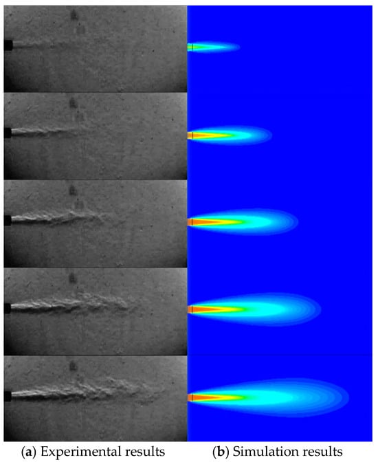
Figure 4.
Comparison of the experimental and simulated jet flow fields at different times.
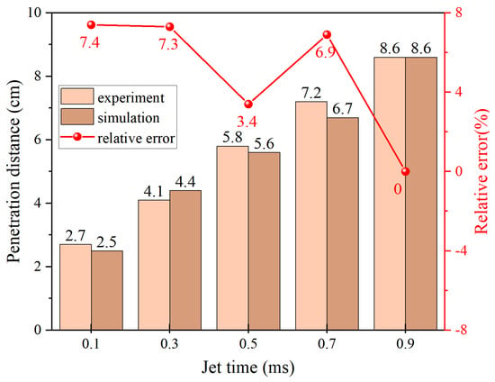
Figure 5.
Comparison of the penetration distances between the experimental and simulation results.
3. Results and Discussion
3.1. Various H2 Concentrations
To systematically investigate the influence of jet-induced disturbances on the flame propagation characteristics of H2-air premixed mixtures, the initial pressure within the 20-L spherical vessel was maintained at 100 kPa, whereas the high-pressure jet tank was pressurized to 500 kPa with CO2 as the jet medium. The experimental protocol employed a fixed jet duration of 100 ms and an ignition delay time of 100 ms. The H2 concentration in the premixed gas mixture was varied at 30%, 50%, and 70%.
3.1.1. The Influence of H2 Concentration on the Characteristics of the Jet Flow Field
Figure 6a,b depict the flow field alterations induced by CO2 jet injection in H2-air mixtures at different concentrations, captured at 100 ms and after a 100 ms stabilization period. Quantitative analysis of the radial distributions in Figure 7a,c,e reveals that increasing the H2 concentration from 30% to 70% enhances both the flow velocity and turbulence intensity while reducing the CO2 molar concentration at fixed radial positions. For example, at time 100 ms and at radius of 10 mm, the average x-velocities are 64.75 m/s, 71.79 m/s, and 82.53 m/s for H2 concentrations of 30%, 50%, and 70%, respectively. Correspondingly, the turbulence intensities are 16.87%, 17.73%, and 18.36%, whereas the molar concentrations of CO2 are 0.25, 0.24, and 0.23, respectively. Figure 7b,d,f depict the corresponding variations in the average values of these three parameters across different radii. The results demonstrate a decrease in the magnitudes of all the parameters at various radii after stabilization compared with their prestabilization values. Nevertheless, the trends in jet parameter variations with increasing H2 concentration remain consistent before and after stabilization, with the flow velocity and turbulence intensity showing an increasing trend, whereas the CO2 mole fraction tends to decrease. This phenomenon originates from the decreased average molecular weight associated with elevated H2 concentrations, which enhances jet medium diffusion into lower molecular weight regions. Consequently, the central flow region exhibits accelerated velocities and intensified turbulence that promote outward CO2 transport, ultimately lowering central CO2 concentrations.
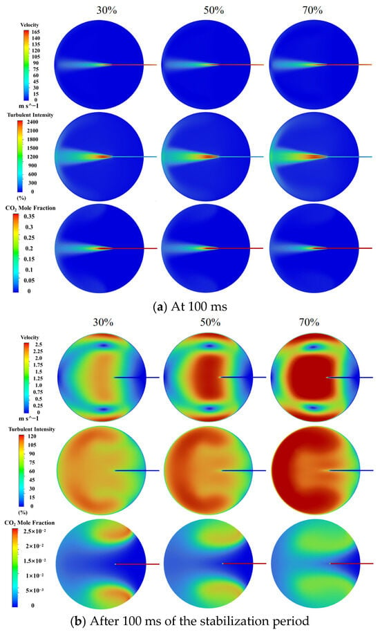
Figure 6.
Cloud maps depicting flow fields under varying H2 concentration conditions (a) at 100 ms (b) after 100 ms of the stabilization period.
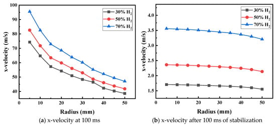
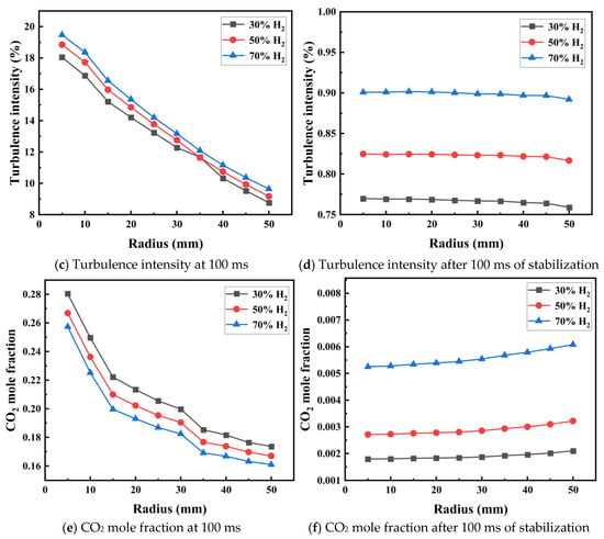
Figure 7.
Average values of flow field parameters at different radii under varying H2 concentrations.
3.1.2. The Influence of H2 Concentration on the Characteristics of the Jet Flow Field
Figure 8 depicts the effect of initial jet-induced disturbances on the flame propagation process in H2-air premixed mixtures across a range of H2 concentrations. As illustrated, at H2 concentrations of 30% and 50%, the jet disturbances induce the formation of a finite number of folds on the flame front. In contrast, at a H2 concentration of 70%, the jet disturbance results in more pronounced and irregular deformations of the flame structure. Furthermore, compared with a static premixed flame, the introduction of initial disturbances leads to an increase in the number of cellular structures on the flame front across all tested H2 concentrations. These observations collectively demonstrate that jet-induced disturbances significantly amplify flame front instabilities, which are characterized by increased wrinkling and cellularization of the flame surface.
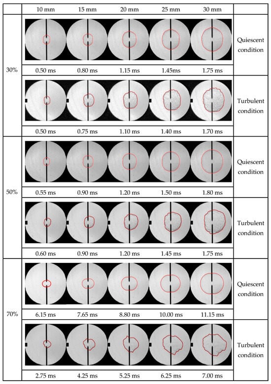
Figure 8.
The influence of initial jet-induced disturbances on the flame propagation process in H2-air premixed gases at various H2 concentrations.
Figure 9 demonstrates the effect of jet-induced disturbances on the flame speed of H2-air mixtures at varying concentrations. The figure reveals the existence of a critical flame radius for all three concentration groups. The critical flame radii were measured as 15.88 mm, 12.96 mm, and 12.88 mm for hydrogen concentrations of 30%, 50%, and 70%, respectively. The introduction of jet disturbances leads to a slight inhibition of the flame propagation velocity when the flame radius is below this critical threshold. Conversely, jet-induced disturbances promote a significant increase in flame propagation speed once the flame radius exceeds the critical value. This phenomenon arises from distinct mechanisms operating at different stages: at smaller flame radii, turbulent effects remain limited, allowing the inhibitory influence of CO2 injection to prevail. The growth in flame radius is accompanied by increased flame front wrinkling, which amplifies the interfacial contact area between the flame and the unburned mixture. This, in turn, accelerates the rate of chemical reactions. Under these conditions, the promoting effect of turbulence on flame propagation becomes more pronounced, outweighing the inhibitory effect of CO2.
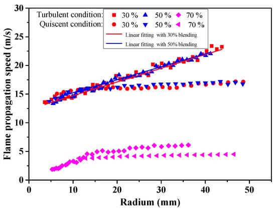
Figure 9.
The influence of jet-induced disturbances on the flame propagation velocity of H2-air premixed gases at various concentrations.
For H2 concentrations of 30%, 50%, and 70%, the static flame propagation velocities at a radius of 35 mm are measured at 16.57 m/s, 16.84 m/s, and 4.35 m/s, respectively. Upon the introduction of jet-induced disturbances, the propagation velocities increase to 20.64 m/s, 20.99 m/s, and 6.11 m/s, representing relative increases of 24.56%, 24.64%, and 40.50%, respectively. Notably, the impact of jet disturbances on the flame propagation velocity is significantly more pronounced at a H2 concentration of 70%. This amplified effect can be attributed to two key factors. First, as illustrated in Figure 7, both the flow field velocity and turbulence intensity are positively correlated with the H2 concentration. Second, the premixed gas with a H2 concentration of 70% has the lowest initial flame propagation velocity, rendering it more susceptible to the interference effects of turbulence, which are known to exert a stronger influence on flames with slower propagation rates [].
Figure 10a–c demonstrate the effect of jet-induced disturbances on the development of the premixed flame front in H2-air mixtures at various H2 concentrations. As illustrated, at a H2 concentration of 30%, the flame front develops localized folds, characterized by predominantly convex shapes near 90° and 270° and concave shapes near 0° and 180°. For a H2 concentration of 50%, jet disturbances generate a finite number of folds during flame development; however, the amplitudes of these local disturbances are relatively small. Furthermore, compared with the 30% H2-air mixture, the distributions of the convex and concave regions along the flame front are less distinct. In contrast, at a H2 concentration of 70%, the flame front exhibits larger-scale folds, and the positions of the convex and concave regions become more irregular following the introduction of the jet. This phenomenon can be primarily explained by the slower flame propagation velocity in the 70% H2-air mixture [], which heightens its susceptibility of the flame to morphological instabilities triggered by initial disturbances.
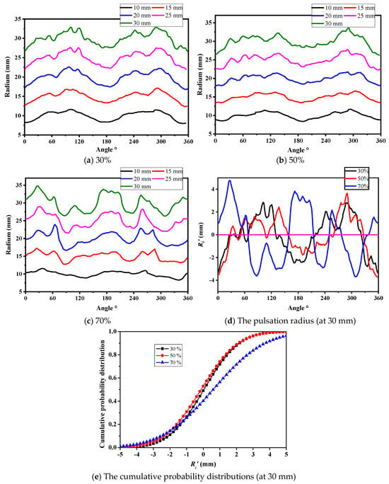
Figure 10.
The evolution process of the flame front in H2-air mixtures at different concentrations and the cumulative probability distribution of the flame front pulsation radius (at 30 mm).
Figure 10d,e present the pulsation radius characteristics at a 30 mm fixed radius for H2-air premixed flames under varying H2 concentrations, accompanied by their corresponding cumulative probability distributions. The experimental data demonstrate that jet disturbances exert a consistent effect on the cumulative probability distribution of the flame pulsation radius for H2 concentrations of 30% and 50%. However, when the H2 concentration reaches 70%, a significant expansion occurs in the range of the cumulative probability distribution for the flame pulsation radius. These results demonstrate that the introduction of jet disturbances most substantially alter the fluctuation amplitude characteristics of the high-concentration premixed flame front morphology.
Figure 11 presents a multiscale decomposition analysis of disturbance characteristics in the flame front of H2-air premixed gas (at 30 mm) with varying H2 concentrations under jet-induced turbulence. The analytical results demonstrate that across the examined H2 concentrations (30%, 50%, and 70%), the flame front fluctuations at finer scales exhibit pronounced stochastic behavior. This observed stochasticity indicates that the spatial distribution of abrupt morphological changes along the flame front of H2-air premixed gas under the specified jet disturbance conditions is fundamentally characterized by inherent unpredictability.
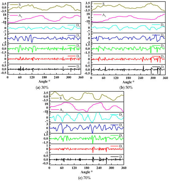
Figure 11.
The multiscale decomposition of the flame front (at 30 mm) of H2-air premixed gas with varying H2 concentrations.
3.2. Various Jet Media
The flame propagation characteristics under different jet media (CO2, N2, He) were investigated via a 20-L spherical vessel containing H2-air premixed gas (30% H2, 100 kPa initial pressure). To ensure consistent jet velocities across different media, the jet tank pressures were precisely regulated: CO2 was maintained at 500 kPa, while the N2 and He pressures were adjusted to match the jet velocity of CO2. All the experiments maintained standardized parameters (100 ms jet duration and 100 ms ignition delay time).
3.2.1. The Influence of Jet Medium Type on the Characteristics of the Jet Flow Field
Figure 12a shows the characteristic flow fields generated by different jet media, whereas Figure 13a,c,e quantitatively depict the radial distributions of key flow field parameters, including velocity profiles, turbulence intensities, and molar concentration distributions. The experimental results reveal distinct behaviors among the tested media: CO2 generates the maximum flow velocity and peak turbulence intensity, whereas He produces the minimum values for both parameters. The flow characteristics of N2 exhibit intermediate values between these two extremes. This phenomenon can be explained by the molecular masses of CO2 (44 g/mol), N2 (28 g/mol), and He (2 g/mol). At equivalent jet flow velocities, media with lower molecular masses demonstrate enhanced velocity dissipation rates during flow development, leading to reduced turbulence generation. With respect to the concentration distributions, the data indicate a clear hierarchy: He achieves the highest molar concentration, followed by N2, with CO2 exhibiting the lowest concentration. This distribution pattern can be attributed to lower velocities producing weaker turbulent mixing, thereby limiting jet medium dispersion and promoting localized accumulation within the flow field.
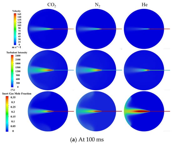
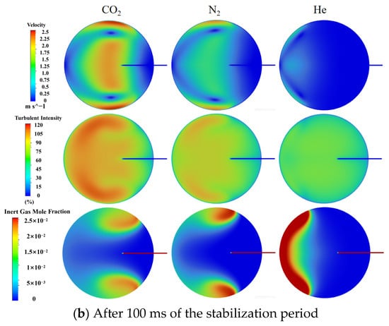
Figure 12.
Cloud maps depicting flow fields under the influence of different jet medium types (a) at 100 ms (b) after 100 ms of the stabilization period.
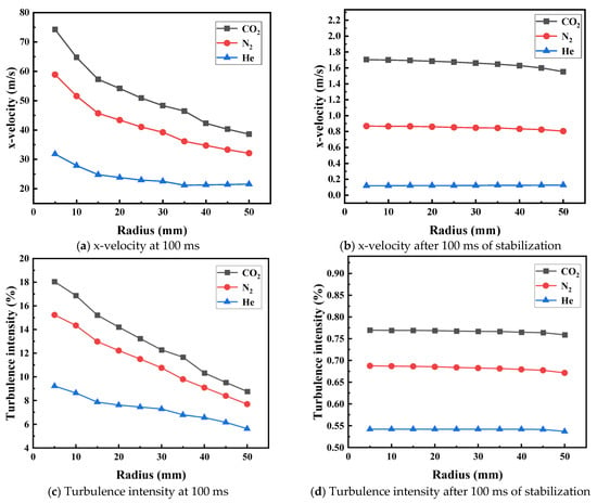
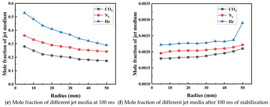
Figure 13.
Average values of flow field parameters at different radii under the influence of different jet medium types.
Figure 12b and Figure 13b,d,f display the stabilized flow fields after 100 ms in different jet media. The stabilization phase trends remain consistent with the initial injection observations: CO2 maintains the maximum velocity and turbulence intensity, and He shows minimum values, with intermediate N2. Compared with CO2, N2 has more localized concentrations, whereas He has the poorest dispersion, accumulating predominantly in the vessel’s right hemisphere because of the reduced flow velocity and turbulence, which inhibits gas diffusion.
3.2.2. The Influence of Jet Medium Type on the Flame Characteristics of H2-Air Mixtures
A comparison of different jet media in Figure 14 reveals their effect on flame propagation. As shown in the figure, the flame attains an identical radius at approximately the same time for all three jet media. Minimal cracking is observed on the flame front when He is employed as the jet medium, resulting in a structure largely resembling that of a static flame. N2 injection induces fewer cracks but causes a noticeable rightward shift in the flame front, resulting in elliptical deformation. The most pronounced morphological changes occur with CO2 as the jet medium, where the entire flame front develops a cellular structure, shifts rightward, and exhibits multiple irregular folds. In summary, under constant jet flow conditions, the CO2 jet has the strongest effect on the flame morphology, followed by N2 and He. As shown in Figure 14, for the same jet flow velocity, a smaller relative molecular mass of the jet medium leads to faster velocity dissipation during the flow process, resulting in a weaker turbulence intensity. The relative molecular masses of CO2, N2, and He are 44, 28, and 2, respectively. Therefore, the turbulence induced by CO2 exerts the most pronounced influence on flame morphology.
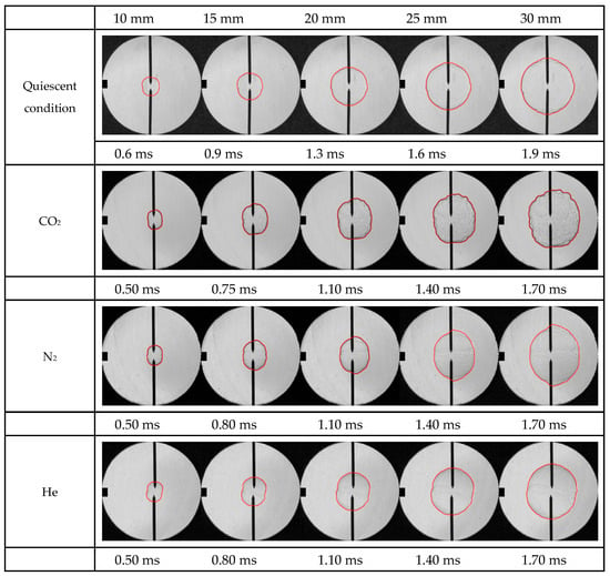
Figure 14.
The influence of jet medium type on the flame propagation process in 30% H2-air premixed gas.
Figure 15 compares the flame propagation velocities resulting from different jet media. The experimental data demonstrate a distinctive critical radius phenomenon at time 100 ms and at radius of 10 mm when CO2 is employed as the jet medium. The underlying reason is that the introduction of the jet not only induces turbulence but also introduces inert gas. Below this critical value, the inhibitory effect of diluting gas mixing dominates, leading to a decrease in flame propagation speed. However, once this critical value is exceeded, the turbulence induced by the jet becomes dominant. This turbulence causes wrinkling of the flame front, increasing its contact area with the unburned gas mixture, thereby significantly enhancing the flame speed. In contrast, both N2 and He exhibit fundamentally different behaviors, with no detectable critical radius and consistent acceleration of the flame propagation velocity upon initial disturbance introduction. This behavioral dichotomy can be attributed to the differential inhibitory characteristics of the jet media, with CO2 exhibiting substantially stronger suppression effects compared to N2 and He.
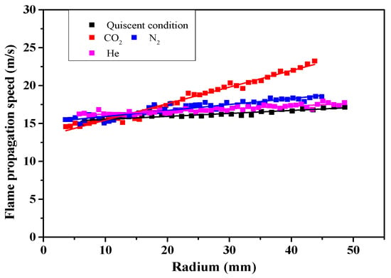
Figure 15.
The influence of the jet medium type on the flame propagation velocity in the 30% H2-air premixed gas.
Figure 16a–c illustrate the influence of the jet medium type on the evolution of the flame profile. According to this figure, during the initial formation stage, the flame front maintains a predominantly smooth morphology. However, with the increasing flame radius, distinct differences in flame morphology emerge across different jet media. When CO2 is used as the jet medium, the number of folds in the flame front gradually increases during flame development. For N2, flame front wrinkling remains stable, yet a substantial increase in fluctuation amplitude occurs at the 90° and 270° positions. When He is used as the jet medium, the flame front undergoes minimal changes as the radius increases. These observations indicate that the CO2 jet has the strongest effect on the flame front morphology, followed by the N2 jet, whereas the He jet has virtually no effect.
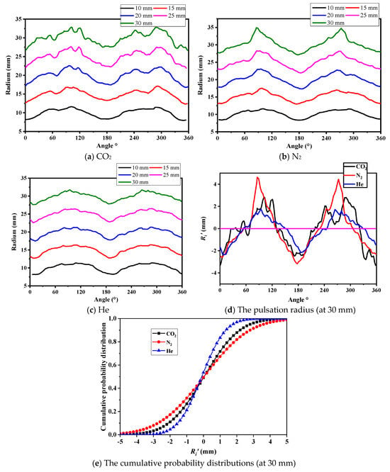
Figure 16.
The evolution process of the flame front in H2-air mixtures under the influence of different jet medium types and the cumulative probability distribution of the flame front pulsation radius (at 30 mm).
Figure 16d shows an analysis of flame front pulsation at a 30 mm radius for 30% H2-air premixed flames under different jet media. Systematically, the flame front shows convex profiles at 90° and 270° and concave depressions at 0° and 180° orientations. When He is employed as the jet medium, the flame front maintains relatively moderate surface curvature. In contrast, N2 induces more pronounced surface deformations, characterized by enhanced convex-concave structures. CO2 induces the most complex morphology, characterized by multiple distinct folds superimposed on the basic convex-concave pattern. The observed phenomena originate from the jet turbulence intensity’s dependence on the medium’s molecular weight: heavier media produce stronger disturbances and horizontal forces on flames. Consequently, N2 yields greater flame front protrusion than He does, whereas CO2 generates the most intense disturbances, significantly increasing flame front wrinkling. Figure 16e compares the cumulative probability distribution of the flame pulsation radius for 30% H2-air mixtures at a 30 mm radius under different jet media. With He, the pulsation radii are concentrated within −3 mm to 3 mm. N2 increases the initial disturbance intensity, resulting in the maximum pulsation amplitude ranging from −5 mm to 5 mm. Interestingly, despite CO2’s strong initial disturbance, its maximum pulsation radius is reduced, falling within the range of −4 mm to 4 mm. This occurs because beyond a critical disturbance threshold, increased flame front wrinkling causes nonuniform radial changes, decreasing the maximum pulsation.
Figure 17 shows the multiscale decomposition analysis of the disturbance characteristics of the flame front (30 mm) in a 30% H2-air premixed gas, classified according to the jet medium type. When N2 is employed as the jet medium, the flame front exhibits pronounced fluctuations in the vicinity of 90° and 270° under low-scale decomposition, indicating the presence of localized abrupt changes induced by jet-induced disturbances. In contrast, the utilization of CO2 or He as the jet medium results in a more stochastic distribution of fluctuation positions at low scales, suggesting a random spatial distribution of abrupt changes in the flame front morphology under these conditions.
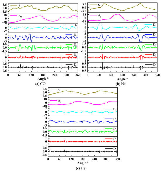
Figure 17.
The multi-scale decomposition of the flame front (at 30 mm) under the influence of different jet medium types.
4. Conclusions
This investigation provides a systematic analysis of jet-induced disturbances on the hydrodynamic flow field and flame front morphology. The research specifically quantifies how the flame propagation velocity, stretch rate, and front wrinkling characteristics depend on the fuel concentration gradient (30%, 50%, and 70% by volume) and jet medium composition (CO2, N2, He). The principal conclusions are delineated as follows:
- (1)
- Quantitative analysis reveals that increasing the H2 molar fraction induces both higher flow velocities and intensified turbulence, a consequence of the inverse relationship between the mixture molecular weight and H2 concentration, which enhances the diffusion of the jet medium toward regions of reduced molecular density.
- (2)
- The utilization of CO2 as the jet medium reveals the existence of a critical flame radius. Below this threshold radius, jet-generated disturbances reduce flame speed as a result of the dominant suppression by the diluent gas. Conversely, beyond this critical radius, the disturbances augment flame propagation as the enhancement effect of initial disturbances prevails.
- (3)
- The impact of jet-generated perturbations on flame morphology is most pronounced in 70% H2-air mixtures owing to their minimal flame propagation velocity, where the decreased flame speed amplifies perturbation-driven structural deformation. In contrast, at elevated propagation velocities, jet disturbances moderately alter the flame surface topology while maintaining overall spherical symmetry.
- (4)
- Experimental evidence has demonstrated that distinct jet media induce differential modifications to the evolution dynamics of the flame front. For He/N2 injection, the predominant longitudinal force component over horizontal forces generates localized flame front discontinuities, specifically at the 90° and 270° azimuthal positions, despite maintaining a globally smooth morphology. Conversely, CO2 injection results in substantial flame front wrinkling with stochastic spatial distribution characteristics.
Current safety standards primarily employ findings from inert gas dilution studies under static conditions. By simulating dynamic leakage scenarios, this work elucidates the turbulence-driven enhancement mechanism of hydrogen explosions, highlighting the necessity of incorporating turbulence-induced risks into practical safety protocols. Moreover, it delineates the dual impact of hydrogen concentration and jet medium molecular weight on turbulence intensity: higher hydrogen concentrations lower the mixture’s molecular weight, promoting diffusion, whereas high-pressure injection of heavier gases like nitrogen and carbon dioxide produces stronger flow disturbances. These findings establish a quantitative foundation for selecting inert gases in explosion suppression systems.
Author Contributions
X.C.: Conceptualization, Funding acquisition, Investigation, Project administration, Formal analysis, Writing—original draft. M.G.: Data curation, Formal analysis, Validation, Writing—original draft. K.W.: Funding acquisition, Resources, Writing—review editing. B.Z.: Resources, Supervision, Writing—review editing. S.X.: Supervision, Writing—review editing. Y.S.: Data curation, Writing—original draft. All authors have read and agreed to the published version of the manuscript.
Funding
This research was supported by the National Natural Science Foundation of China, 52404269; Beijing Municipal Science and Technology Project, Z231100003823022; Independent Research fund of Joint National-Local Engineering Research Centre for Safe and Precise Coal Mining (Anhui University of Science and Technology), EC2023008; the State Key Laboratory Cultivation Base for Gas Geology and Gas Control (Henan Polytechnic University, WS2023B10); College Students’ Innovative Entrepreneurial Training Plan Program of China University of Mining and Technology (Beijing), 202412021.
Institutional Review Board Statement
This study did not involve humans or animals.
Informed Consent Statement
This study did not involve humans or animals.
Data Availability Statement
The datasets used and/or analyzed during the current study are available from the corresponding author, Bo Zhang, on reasonable request via e-mail: bozhang@sjtu.edu.cn.
Acknowledgments
We sincerely thank the anonymous reviewers for their critical comments and suggestions on improving the manuscript.
Conflicts of Interest
The authors declare no conflicts of interest.
References
- Evro, S.; Oni, B.A.; Tomomewo, O.S. Carbon neutrality and hydrogen energy systems. Int. J. Hydrogen Energy 2024, 78, 1449–1467. [Google Scholar] [CrossRef]
- Moudio, N.D.N.; Bian, X.Q.; Chinamo, D.S. Liquid hydrogen carriers for clean energy systems: A critical review of chemical hydrogen storage strategies. Fuel 2026, 404, 136329. [Google Scholar] [CrossRef]
- Cirrone, D.; Makarov, D.; Proust, C.; Molkov, V. Minimum ignition energy of hydrogen-air mixtures at ambient and cryogenic temperatures. Int. J. Hydrogen Energy 2023, 48, 16530–16544. [Google Scholar] [CrossRef]
- Shashidharan, S.; Velamati, R.K.; Kumar, S.; Veetil, J.E. Hot surface ignition of H2-air and CH4-H2-air mixtures for various equivalence ratios and heating Rates. Int. J. Hydrogen Energy 2024, 53, 770–779. [Google Scholar] [CrossRef]
- Plaksin, V.Y.; Kirillov, I.A. Hydrogen flammability and explosion concentration limits for a wide temperature range. J. Loss Prev. Process Ind. 2025, 94, 105554. [Google Scholar] [CrossRef]
- Kang, J.; Su, T.; Li, J.; Wang, Z.; Zhang, J. Research on risk evolution, prevention, and control of fire and explosion accidents in hydrogen refueling stations based on the AcciMap-FTA model. Process Saf. Environ. Protect. 2025, 194, 107–118. [Google Scholar] [CrossRef]
- Moses, J.K.; Tivfa, T.A.; Qasem, N.A.A.; Alquaity, A.B.S. Combustion characteristics of hydrogen, ammonia, and their blends: A review. Fuel 2025, 388, 30. [Google Scholar] [CrossRef]
- Xie, Y.; Yang, J.; Ahmed, P.; Thorne, B.J.A.; Gu, X. Three-dimensional dynamics of unstable lean premixed hydrogen-air flames: Intrinsic instabilities and morphological characteristics. Combust. Flame 2025, 271, 113800. [Google Scholar] [CrossRef]
- Xie, Y.; Morsy, M.E.; Li, J.; Yang, J. Intrinsic cellular instabilities of hydrogen laminar outwardly propagating spherical flames. Fuel 2022, 327, 125149. [Google Scholar] [CrossRef]
- Reyes, M.; Tinaut, F.V.; Giménez, B.; Camaño, A. Combustion and Flame Front Morphology Characterization of H2-CO Syngas Blends in Constant Volume Combustion Bombs. Energy Fuels 2021, 35, 3497–3511. [Google Scholar] [CrossRef]
- Yang, Z.; Zhang, B. Typical onset modes of DDT and behavior of strong transverse shocks. Chin. J. Aeronaut. 2025, 103602. [Google Scholar] [CrossRef]
- Xie, Y.; Yang, J.; Gu, X. Flame wrinkling and self-disturbance in cellularly unstable hydrogen-air laminar flames. Combust. Flame 2024, 265, 113505. [Google Scholar] [CrossRef]
- Kim, W.K.; Mogi, T.; Kuwana, K.; Dobashi, R. Self-similar propagation of expanding spherical flames in large scale gas explosions. Proc. Combust. Inst. 2015, 35, 2051–2058. [Google Scholar] [CrossRef]
- Bao, S.; Zhao, H.; Li, X.; Tian, F.; Liu, Z.; Li, G.; Yuan, C. Investigation on decelerated propagation of hydrogen-air premixed flames in confined space. Process Saf. Environ. Prot. 2024, 192, 973–982. [Google Scholar] [CrossRef]
- Mei, Y.; Shuai, J.; Li, Y.; Zhou, N.; Ren, W.; Ren, F. Flame acceleration process of premixed hydrogen in confined space with different obstacle shapes. Fuel 2023, 334, 126624. [Google Scholar] [CrossRef]
- Galmiche, B.; Mazellier, N.; Halter, F.; Foucher, F. Turbulence characterization of a high-pressure high-temperature fan-stirred combustion vessel using LDV, PIV and TR-PIV measurements. Exp. Fluids 2014, 55, 20. [Google Scholar] [CrossRef]
- Li, Y.; Bi, M.; Gao, W.; Zhou, Y.; Huang, L. Interaction of flame instabilities and pressure behavior of hydrogen-propane explosion. J. Loss Prev. Process Ind. 2020, 64, 104078. [Google Scholar] [CrossRef]
- Saeid, M.H.; Khadem, J.; Emami, S.; Oh, C.B. Numerical Investigation of the Effects of Diffusion Time on the Mechanisms of Transition from a Turbulent Jet Flame to Detonation in a H2-Air Mixture. Fire 2023, 6, 434. [Google Scholar] [CrossRef]
- Wang, L.; Ma, H.; Shen, Z.; Chen, D. The influence of an orifice plate on the explosion characteristics of hydrogen-methane-air mixtures in a closed vessel. Fuel 2019, 256, 115908. [Google Scholar] [CrossRef]
- Wang, K.; Su, M.; Wei, L.; Chen, S.; Kong, X.; Fang, Y. Effect of initial turbulence on explosion behavior of stoichiometric methane-ethylene-air mixtures in confined space. Process Saf. Environ. Prot. 2022, 161, 583–593. [Google Scholar] [CrossRef]
- Kundu, S.K.; Zanganeh, J.; Eschebach, D.; Badat, Y.; Moghtaderi, B. Confined explosion of methane-air mixtures under turbulence. Fuel 2018, 220, 471–480. [Google Scholar] [CrossRef]
- Cai, P.; Liu, Z.; Li, M.; Zhao, Y.; Li, P.; Li, S.; Li, Y. Experimental study of effect of equivalence ratio and initial turbulence on the explosion characteristics of LPG/DME clean blended fuel. Energy 2022, 250, 123858. [Google Scholar] [CrossRef]
- Chang, X.; Zhang, B.; Ng, H.D.; Bai, C. The effects of pre-ignition turbulence by gas jets on the explosion behavior of methane-oxygen mixtures. Fuel 2020, 277, 118190. [Google Scholar] [CrossRef]
- Chang, X.; Bai, C.; Zhang, B. The effect of gas jets on the explosion dynamics of hydrogen-air mixtures. Process Saf. Environ. Prot. 2022, 162, 384–394. [Google Scholar] [CrossRef]
- Dong, C.; Zhou, Q.; Zhang, X.; Zhao, Q.; Xu, T.; Hui, S. Experimental study on the laminar flame speed of hydrogen/natural gas/air mixtures. Front. Chem. Eng. China 2010, 4, 417–422. [Google Scholar] [CrossRef]
- Ganatra, K.A.; Chattopadhyay, H.; Mathur, A. Investigation of free and impinging jets using generalized k-ω (GEKO) turbulence model. Int. J. Heat Fluid Flow 2025, 111, 109660. [Google Scholar] [CrossRef]
- Kumar, S.; Huang, R.; Hsu, C.M. Effects of pulsation intensity on the flow and dispersion of pulsed dual plane jets. Int. J. Mech. Sci. 2021, 193, 106182. [Google Scholar] [CrossRef]
- Yuan, M.; Hu, Q.; Yang, H.; Wang, X.; Wang, J.; Qian, X.; Li, P.; Pang, L.; Gao, Y. Evolution of Explosion-Venting Flow Field and Hazard Induced by a Vented Hydrogen Explosion in a 45 m3 Container. Energy Fuels 2024, 38, 16924–16935. [Google Scholar] [CrossRef]
- Kong, X.; Zhang, Y.; Li, G.; Lu, X.; Zhu, J.; Xu, J. Effects of Mainstream Velocity and Turbulence Intensity on the Sweeping Jet and Film Composite Cooling. Machines 2023, 11, 356. [Google Scholar] [CrossRef]
- Maghrabie, H.M. Heat transfer intensification of jet impingement using exciting jets—A comprehensive review. Renew. Sust. Energy Rev. 2021, 139, 110684. [Google Scholar] [CrossRef]
- Seif, A.A.; Zedan, M.F.; Shibl, A. Effect of Nozzle Exit Geometry on the Development of Turbulent jets. J. King Saud Univ.-Eng. Sci. 1994, 6, 217–239. [Google Scholar] [CrossRef]
- Yang, Z.; Zhang, B. Numerical and experimental analysis of detonation induced by shock wave focusing. Combust. Flame 2023, 251, 112691. [Google Scholar] [CrossRef]
- Sementa, P.; Tornatore, C.; Catapano, F.; Altieri, N. Impact of injection parameters on hydrogen combustion: Flame propagation and stability in ultra-lean mixtures. Int. J. Hydrogen Energy 2025, 143, 615–626. [Google Scholar] [CrossRef]
- Czwielong, F.; Becker, S. Active Turbulence Grid-Controlled Inflow Turbulence and Replication of Heat Exchanger Flow Fields in Fan Applications. Int. J. Turbomach. Propuls. Power 2023, 8, 1. [Google Scholar] [CrossRef]
- Arabkhalaj, A.; Verwey, C.; Birouk, M. Background vapor effect on droplet evaporation in a turbulent flow at elevated pressure. Proc. Combust. Inst. 2024, 40, 105523. [Google Scholar] [CrossRef]
- Arabkhalaj, A.; Verwey, C.; Birouk, M. Experimental study of butanol droplet evaporation in a turbulent, high-pressure environment. Fuel 2023, 353, 129143. [Google Scholar] [CrossRef]
- Nishino, T.; Willden, R.H.J. Effects of 3-D channel blockage and turbulent wake mixing on the limit of power extraction by tidal turbines. Int. J. Heat Fluid Flow 2012, 37, 123–135. [Google Scholar] [CrossRef]
- Kang, Y.; Lee, G.; Lee, K.M. Experimental study of turbulence and flame characteristics on low swirl burner integrated with modified square fractal grids. Appl. Therm. Eng. 2025, 258, 124440. [Google Scholar] [CrossRef]
- Lu, Y.S.; Zhong, X.X.; Liu, Z.Q.; Zhong, Q.; Chen, T.F. Bidirectional propagation characteristics of gas explosion disturbed by accumulated obstacles with varied blockage ratios. Fuel 2024, 374, 132472. [Google Scholar] [CrossRef]
- Zhang, B.; Li, Y.; Liu, H. Analysis of the ignition induced by shock wave focusing equipped with conical and hemispherical reflectors. Combust. Flame 2022, 236, 111763. [Google Scholar] [CrossRef]
- Wang, C.; Zhang, B. Experimental Study on the Detonation Propagation Behavior in a Thin Cylindrical Chamber. Aerosp. Sci. Technol. 2025, 159, 109988. [Google Scholar] [CrossRef]
- Chakraborty, N.; Dopazo, C. Timescales Associated with the Evolution of Reactive Scalar Gradient in Premixed Turbulent Combustion: A Direct Numerical Simulation Analysis. Fire 2024, 7, 73. [Google Scholar] [CrossRef]
- Yan, B.; Sun, C.; Feng, Q.; Chen, J.; Gao, Y.; Tao, C. The Study of Hydrogen Volume Fraction Effects on the Flame Temperature of Turbulence Diffusion Propane Jet Flames. Fire 2024, 7, 10. [Google Scholar] [CrossRef]
- Gopinathan, S.M.; Surendran, A.; Heckl, M.A. Hydrogen-blended fuels: Nonlinear flame dynamics and safe operation limits. Int. J. Hydrogen Energy 2025, 111, 371–384. [Google Scholar] [CrossRef]
- Dinesh, K.; Shalaby, H.; Luo, K.; Oijen, J.A.; Thévenin, D. High hydrogen content syngas fuel burning in lean premixed spherical flames at elevated pressures: Effects of preferential diffusion. Int. J. Hydrogen Energy 2016, 41, 18231–18249. [Google Scholar] [CrossRef]
- Wang, J.; Zhang, M.; Huang, Z.; Kudo, T.; Kobayashi, H. Measurement of the instantaneous flame front structure of syngas turbulent premixed flames at high pressure. Combust. Flame 2013, 160, 2434–2441. [Google Scholar] [CrossRef]
- Sun, S.; Qiu, Y.; Xing, H.; Wang, M. Effects of concentration and initial turbulence on the vented explosion characteristics of methane-air mixtures. Fuel 2020, 267, 117103. [Google Scholar] [CrossRef]
- Kaminski, C.F.; Hult, J.; Aldén, M.; Lindenmaier, S.; Dreizler, A.; Maas, U.; Baum, M. Spark ignition of turbulent methane/air mixtures revealed by time-resolved planar laser-induced fluorescence and direct numerical simulations. Proc. Combust. Inst. 2000, 28, 399–405. [Google Scholar] [CrossRef]
- Haq, M.Z.; Sheppard, C.G.W.; Woolley, R.; Greenhalgh, D.A.; Lockett, R.D. Wrinkling and curvature of laminar and turbulent premixed flames. Combust. Flame 2002, 131, 1–15. [Google Scholar] [CrossRef]
- Chang, X.Y.; Li, Y.F.; Yao, N.; Wang, K.; Zhou, B. Propagation characteristics and inherent instability of hydrogen-air premixed flame with inert gas dilution. Int. J. Hydrogen Energy 2024, 84, 132–145. [Google Scholar] [CrossRef]
Disclaimer/Publisher’s Note: The statements, opinions and data contained in all publications are solely those of the individual author(s) and contributor(s) and not of MDPI and/or the editor(s). MDPI and/or the editor(s) disclaim responsibility for any injury to people or property resulting from any ideas, methods, instructions or products referred to in the content. |
© 2025 by the authors. Licensee MDPI, Basel, Switzerland. This article is an open access article distributed under the terms and conditions of the Creative Commons Attribution (CC BY) license (https://creativecommons.org/licenses/by/4.0/).