Abstract
In response to the demands for high reliability, excellent dynamic response, and high-precision control of advanced aircraft actuation systems, this study focuses on the control technology for the master-master operating mode of dual-redundancy electro-hydrostatic actuation (EHA) systems. A multi-domain coupling model integrating motor magnetic circuit saturation, hydraulic viscosity-temperature characteristics, and mechanical clearances was established, based on which a current-loop decoupling technique using vector control was developed. Furthermore, the study combined adaptive sliding mode control (ASMC) and an improved active disturbance rejection control (ADRC) to enhance the robustness of the speed loop and the disturbance rejection capability of the position loop, respectively. To address the key challenges of synchronous error accumulation and uneven load distribution in the master-master mode, a dual-redundancy dynamic model accounting for hydraulic coupling effects was developed, and a two-level cooperative control strategy of "position synchronization-dynamic load balancing" was proposed based on the cross-coupling control (CCC) framework. Experimental results demonstrate that the position loop control error is less than ±0.02 mm, and the load distribution accuracy is improved to over 97%, fully meeting the design requirements of advanced aircraft. These findings provide key technical support for the engineering application of power-by-wire flight control systems in advanced aircraft.
1. Introduction
With the development of aviation equipment towards intelligence and unmanned operation, flight control actuation systems need to simultaneously meet the requirements of mission reliability and a dynamic performance under extreme working conditions [,]. Electro-hydrostatic actuation (EHA) systems have become the mainstream solution for advanced aircraft actuation systems due to their advantages of a high power density, flexible installation space, and low maintenance costs [,,]. However, single-point failures in a single EHA system may lead to flight control failure. Thus, dual-redundancy technology has become the core means to improve mission reliability through physical redundancy [,].
Conventional dual-redundancy systems mostly adopt the “master-standby” working mode, where the standby unit only switches in when the main unit fails []. This mode has two major defects []: (1) the long-term cold backup of the standby unit causes a performance drift in the components, which are prone to dynamic shocks during switching, and (2) only a single system operates under normal conditions, with a power capacity utilization of less than . The master-master working mode, through the synchronous participation of the dual-redundancy units in control, can achieve utilization of the power capacity. This has become a key research direction for new-generation civil and military aircraft [,].
The classical control methods commonly used in early flight control actuation systems have struggled to meet the control requirements of electro-hydrostatic actuation systems in terms of their steady-state error and disturbance rejection capability [,,]. In recent years, progress has been made in intelligent control algorithms. The adaptive fuzzy PID control proposed in Ref. [] improves the disturbance rejection accuracy to less than 0.5 mm, but the engineering tuning of the fuzzy rule base takes up to more than 200 h. The sliding mode control (SMC) scheme in Ref. [] enhances the robustness through sign function switching, but introduces high-frequency chattering, reducing the service life of the hydraulic valves by .
Early studies mostly adopted parallel control strategies based on the rigid shaft hypothesis. For example, Ali et al. [] achieved position synchronization through dual-closed-loop PI control, but the synchronization error could reach as high as when the hydraulic parameters were mismatched (such as a pump volumetric efficiency deviation >). To address the problem of coupling interference, cross-coupling control (CCC) was introduced []. Fan et al. [] designed a cross-coupling controller based on robust PID, reducing the synchronization error to , but the fixed gain was difficult to adapt to variable load conditions. In recent years, intelligent control algorithms have become a research hotspot. Yao et al. [] proposed a fuzzy adaptive cross-coupling strategy, which stabilized the synchronization error at under a ± load fluctuation, but the algorithm complexity prolonged the control cycle to 20 ms, exceeding the real-time requirement of no more than 3 ms for flight control actuation systems.
The uneven load distribution in dual-redundancy EHA systems is mainly caused by the nonlinearity of hydraulic components (such as the dead zones of pumps/valves) and mechanical installation errors (such as the friction coefficient deviation of hydraulic cylinders) []. Conventional pressure difference feedback control adjusts the load distribution through proportional flow valves. Zhou et al. [] used a disturbance observer to compensate for nonlinear factors, controlling the load distribution error within , but the viscosity-temperature variation of hydraulic oil (e.g., −40 °C to +80 °C) will lead to the mismatch of the compensation model. Sliding mode control is widely applied due to its strong robustness against uncertainties. Hong et al. [] designed a sliding mode controller, shortening the load error convergence time to 50 ms, but the switching term of the conventional sign function easily caused high-frequency chattering, aggravating the wear of hydraulic valves.
The dual-redundancy EHA system proposed in this study achieved performance breakthroughs through the deep integration of mechanical, electrical, and hydraulic systems and control coupling, as follows:
Physical-layer redundancy: two independent “motor-pump-sensor” channels realize force synthesis through the coaxial drive of the actuator.
Control-layer collaboration: in the master-master working mode, dual channels synchronously track commands, with a load-sharing error of less than .
The main innovations of the master-master control strategy are as follows:
(1) A two-level collaborative algorithm of “position synchronization-dynamic load balancing” was studied, with a position synchronization calculation time of less than 3 ms.
(2) Dynamic synchronization technology: A high-precision dual-channel synchronization error monitoring model was established. Combined with 40 Mbps high-speed communication and a 100 s ultra-short synchronization calculation period, real-time error capture was realized. A phase compensation dynamic adjustment mechanism was innovatively introduced to effectively eliminate the displacement cumulative error caused by the phase difference, ensuring the accuracy of system operation.
(3) Adaptive load-balancing strategy: The causes of load imbalances, such as hardware, control delays, and external interference, were analyzed in depth. An intelligent current loop-balancing algorithm based on deviation coupling was designed to achieve the dynamic optimization of torque commands. By integrating hydraulic pressure feedforward compensation technology, a closed-loop feedback regulation system was constructed, significantly improving the load-sharing accuracy and the system’s anti-interference ability.
2. Multi-Domain Coupling Modeling of EHA System
2.1. Composition of EHA System
The EHA is a typical “electric-machine-hydraulic” coupled system. Its core components include the permanent magnet synchronous motor (PMSM), hydraulic pump, actuator cylinder, etc. The dynamic characteristics of these components are mutually coupled, and a refined modeling approach is required to describe the overall system behavior. The following elaborates on the modeling of each core component, coupling relationships, and key nonlinear factors. The principle diagram is shown in Figure 1.
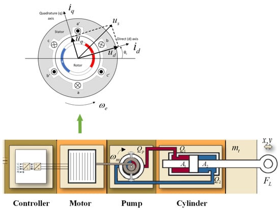
Figure 1.
EHA system schematic block diagram.
2.2. Model of PMSM
As the power source of the EHA, the PMSM model must reflect the coupling characteristics of electrical properties, magnetomotive force, and mechanical motion. It is typically constructed based on the dq-axis synchronous rotating coordinate system (with the conversion from the three-phase stationary coordinate system to the synchronous rotating coordinate system realized via Clark transformation and Park transformation).
Voltage balance equations describe the relationship between the stator winding voltage, current, and rotational speed:
where are d/q-axis voltages (V); are d/q-axis currents (A); is stator resistance (); are d/q-axis inductances (H); Electrical angular velocity , where p is the number of pole pairs and is the mechanical angular velocity (rad/s); is permanent magnet flux linkage (Wb).
Electromagnetic torque equation is the output torque of the motor, which consists of the permanent magnet torque and the reluctance torque (for interior-mounted PMSMs):
Mechanical motion equation describes that the output torque of the motor balances the load torque, inertial force, and damping force:
where is moment of inertia of the motor (kg·m2); is viscous damping coefficient (N·m·s/rad); is load torque (mainly the input torque of the hydraulic pump, N·m).
2.3. Model of Hydraulic Pump (Taking Fixed-Displacement Piston Pump as an Example)
The hydraulic pump is the energy conversion component of the EHA, converting the mechanical energy of the motor into hydraulic energy. Its model needs to describe the flow output characteristics and torque load characteristics.
(1) Flow characteristics
Theoretical flow is determined by the motor speed and pump displacement:
where is the pump displacement (m3/rad) and is the mechanical angular velocity of the motor (rad/s).
For actual flow, the internal leakage (mainly leakage from the piston-cylinder block gap) and external leakage (housing leakage) need to be deducted, and the leakage volume is related to the pressure difference:
where is pressure difference across the pump inlet and outlet (Pa), where is the high-pressure side pressure and is the low-pressure side pressure; is internal leakage coefficient (m3/(Pa·s)), related to the gap and oil viscosity; is external leakage coefficient (usually small and negligible). Under high-speed and high-pressure conditions, leakage may exhibit nonlinearity (turbulent flow characteristics), requiring correction to .
(2) Torque characteristics
The input torque of the pump (i.e., the motor load torque ) is determined by the hydraulic power and efficiency:
where is the mechanical efficiency of the pump (considering friction losses, usually 0.85 ∼ 0.95). Friction losses include friction between the piston and cylinder block, and between the sliding shoe and swash plate, which can be modeled as (where is the viscous friction coefficient and is the Coulomb friction torque).
2.4. Model of Actuator Cylinder (Hydraulic Cylinder)
The actuator cylinder is the executive component of the EHA, converting hydraulic energy into mechanical energy (linear motion). Its model is based on the flow continuity equation and force balance equation.
(1) Flow continuity equation
The flow in the two chambers (rodless chamber/rod chamber) of the actuator cylinder must balance the pump input flow, leakage flow, and flow change caused by oil compressibility.
For rodless chamber (area ), the flow satisfies
And for rod chamber (area ), the flow satisfies
where is flow into the rodless chamber/rod chamber (m3/s); is piston speed of the actuator cylinder (m/s), where x is the displacement; are internal leakage volumes of the two chambers (related to ); are volumes of oil in the two chambers (m3); is effective bulk modulus of oil (Pa, usually ).
For an EHA with a closed-loop circuit, the pump output flow and the actuator cylinder flow satisfy
where the sign depends on the motor rotation direction.
(2) Force balance equation
The resultant force on the piston is equal to the sum of the inertial force, damping force, load force, etc.
where is total mass of the piston and load (kg); is viscous damping coefficient (N·s/m); is piston friction resistance using the Stribeck model
where is static friction, is Coulomb friction, and is Stribeck velocity; is external load force (N), such as aerodynamic load and mechanical resistance.
2.5. System Coupling Relationships
The components of the EHA are coupled through “energy flow” and “signal flow”, with the core transfer paths as follows:
(1) From motor to pump: The motor speed determines the theoretical flow of the pump; the pump load torque acts back on the motor, affecting the motor speed (mechanical coupling).
(2) From pump to actuator cylinder: The pump output flow determines the piston speed v of the actuator cylinder; the pressure difference between the two chambers of the actuator cylinder affects the pressure difference across the pump inlet and outlet, thereby changing the pump load torque (hydraulic-mechanical coupling).
(3) From actuator cylinder to load: The piston displacement x tracks the load demand, and the load force affects the dynamics of the pump and motor through pressure feedback (load coupling).
3. Engineering Design Architecture of Dual-Redundancy EHA System
3.1. Architecture of EHA
The EHA system is an electrical-mechanical-hydraulic dual-redundancy system. System I and System II of the actuator are connected to the two chambers of a series actuator cylinder. Under normal conditions, both systems operate in a master-master configuration, jointly outputting displacement and pressure to drive the load. If any system fails, it will be bypassed while the other system continues to operate normally, putting the actuator in a fail-operational state. After both systems fail, the actuator will move to the neutral position under the action of an external pneumatic load and achieve hydraulic locking, entering a fail-safe state. A permanent magnet synchronous motor drives a bidirectional hydraulic pump to rotate. The output flow of the hydraulic pump, in accordance with the motor’s speed and direction, directly controls the position, speed, and direction of the actuator cylinder. An accumulator serves as the oil tank of the EHA system, compensating for temperature changes and providing backpressure to the hydraulic pump. Solenoid valves and mode valves together accomplish the mode of the actuator. High-pressure sensors are used to monitor the pressure in the two chambers of the hydraulic pump, calculate the magnitude of the load force, and conduct fault monitoring. A low-pressure sensor with the ability to measure the temperature monitors the accumulator pressure and oil temperature. The structure of the dual-redundancy electro-hydrostatic actuator is shown in Figure 2.
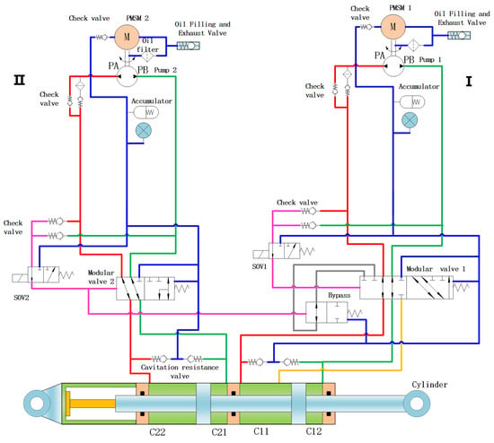
Figure 2.
Engineering design architecture diagram of dual-redundancy EHA system. The right side of the actuator uses Hydraulic System I, and the left side of the actuator uses Hydraulic System II.
3.2. Architecture of Actuator Electronics Controller
The actuator electronics controller (ACE) consists of an electronic control unit and a power drive unit. The electronic control unit implements functions such as redundancy management, motor drive algorithms, signal input/output conditioning, and bus data processing, while the power drive unit realizes functions such as power driving. The structure of the actuator controller is shown in Figure 3.
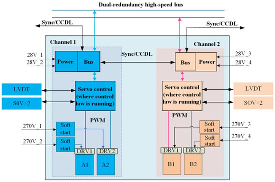
Figure 3.
ACE architecture diagram.
The EHA and ACE are connected via hardwiring, including signals such as ABC three-phase electrical drive signals, an SOV signal power supply and feedback, sensor power supply signals, linear variable differential transformer (LVDT) sensor power supply and feedback, resolver power supply and feedback, and temperature acquisition signals. The connection between ACE and EHA is shown in Figure 4.

Figure 4.
Connections between ACE and EHA diagram.
A diagram of the control loop is shown in Figure 5, where , , and respectively represent the three-phase currents of the motor; represents the electrical angle of the motor; and x represents the position feedback of the actuator.
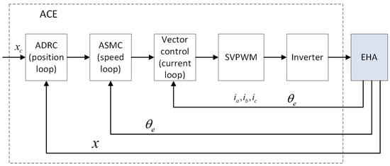
Figure 5.
The control loop diagram.
4. Control Algorithm Design
4.1. Current Loop Vector Control and DQ-Axis Decoupling Technology
4.1.1. Vector Control and Coordinate Transformation
The core of vector control is to convert a three-phase AC motor into an equivalent DC motor representation through coordinate transformation, enabling the independent control of the excitation current and torque current. The specific transformation process is as follows.
The Clark transformation (abc→) converts voltages/currents in the three-phase stationary coordinate system to a two-phase stationary coordinate system []:
The Park transformation (→dq) converts to a synchronous rotating coordinate system via the rotor position angle :
where , p is the number of pole pairs, is the mechanical angle, and is the initial electrical angle [].
4.1.2. DQ-Axis Voltage Equation and Decoupling Control
In the synchronous rotating coordinate system, the voltage equation of PMSM is as follows []:
It can be seen that the dq-axis voltages have cross-coupling terms ( and ). To achieve decoupling, a feedforward compensator was designed to eliminate the coupling terms, yielding the following decoupled voltage commands []:
By measuring the electrical angular velocity and feedback currents and in real time, the cross-coupling effects can be dynamically compensated to achieve independent dq-axis control.
4.1.3. Current Loop Control Law Design
The current loop is designed with a proportional-integral (PI) controller, and the control law is
where and are the PI controller parameters for the dq-axis [].
4.1.4. High-Speed Flux-Weakening Control Strategy
When the motor speed exceeds the base speed, the speed regulation range is expanded through flux-weakening control []. The flux-weakening criterion is defined as follows:
The excitation current command under flux-weakening control is
where the exponential factor n is the flux-weakening intensity coefficient. is adjusted in real time through a flux observer to suppress back-EMF saturation, enabling the flux-weakening speed regulation range to reach several times the rated speed.
4.2. Adaptive Sliding Mode Control for Speed Loop
4.2.1. Basic Theory of Sliding Mode Control
Sliding mode control forces the system state to converge to a preset sliding surface within a finite amount of time by designing a discontinuous control law. It performs a sliding motion along the sliding surface, which has an inherent robustness to parameter perturbations and external disturbances. For the speed loop control object, the speed error is defined as , where is the speed command and is the actual speed. The sliding surface is designed as follows []:
when the system state reaches the sliding surface (), the sliding condition is satisfied. At this time, the dynamic characteristics are determined by the sliding surface equation, which is independent of the system parameters, achieving decoupling control for uncertainties.
4.2.2. Design of Adaptive Sliding Mode Controller
An adaptive sliding mode controller (ASMC) was designed for the time-varying moment of inertia (such as ) and friction nonlinearity (combined action of Coulomb friction and viscous friction) of the pump-controlled electro-hydrostatic actuation system. The speed loop takes the output by the current loop as the control quantity, and the control law is divided into two parts: equivalent control and switching control :
(1) Equivalent control law (handling matched uncertainties).
Assuming that the system is on the sliding surface (), the equivalent control quantity can be obtained from the sliding surface equation:
where is the motor torque coefficient, is the load torque, and B is the viscous damping coefficient. In practical applications, since J and are unknown, they need to be estimated online through an adaptive mechanism.
(2) Switching control law (handling mismatched uncertainties).
To force the system state to converge to the sliding surface quickly, a switching control term was designed:
where is a saturation function (replacing the conventional sign function to suppress chattering):
where is the boundary layer thickness (such as ) and is the switching gain, which is dynamically adjusted by an adaptive law to adapt to load changes.
4.2.3. Implementation of Adaptive Mechanism
To cope with the strong uncertainties of the moment of inertia J (variation range of ) and load torque (fluctuation of ) in the pump-controlled electro-hydrostatic actuation system, a fuzzy-logic-based adaptive algorithm was designed to improve the robustness of the sliding mode controller by adjusting the control parameters online. This mechanism includes four core links-input fuzzification, rule base construction, fuzzy inference, and defuzzification, which are implemented as follows.
Considering the uncertainties of the moment of inertia J and load torque , a fuzzy logic adaptive algorithm was introduced to adjust the control parameters online.
(1) The processing of input variables and the universe of discourse mapping.
We defined the mapping from physical quantities to the fuzzy universe of discourse. The speed error () and error change rate () are defined as input variables, which are mapped from the physical domain to the fuzzy universe through quantization factors :
where the quantization factors are determined according to the maximum working conditions. Then, the division of the fuzzy universe of discourse is carried out. Five symmetric fuzzy subsets were used to describe the input variables: NB (negative large), NM (negative medium), ZO (zero), PM (positive medium), and PB (positive large). The membership function uses a Gaussian type:
where is the central value and is the width parameter, ensuring an overlap of the subset to balance the control sensitivity and stability.
(2) The output variable design and scale factors.
The output variables are the switching gain (which affects the chattering intensity) and the sliding mode coefficient (which determines the slope of the sliding surface); they are mapped from the fuzzy universe to the physical domain through the scale factors and :
where (unit: V/A) is determined according to the voltage-withstanding ability of the power devices and motor characteristics and (unit: ) matches the system bandwidth through a frequency domain analysis.
(3) The construction of the fuzzy control rule base, which is based on the Lyapunov stability theory and the engineering debugging experience.
A total of 49 control rules in a 5 × 5 were established. The core rule design principles are as follows:
Error-dominated rules: When is PB, increase to reduce the error quickly, and increase to improve the response speed.
Error change rate-dominated rules: When is NB (the error decreases rapidly), decrease to prevent overshooting.
Rules near zero error: When both and are ZO, use medium gain to maintain a steady-state accuracy.
The typical rules are shown in Table 1.

Table 1.
Example of typical rules.
The rule base satisfies symmetry (mirror response for positive/negative errors) and completeness (covering all input combinations), and passes consistency checks to ensure no conflicting rules.
(4) Fuzzy inference and defuzzification.
Mamdani-type inference was used, and the rule activation degree was calculated using the “minimum method”:
where and are the membership degrees of the input variables to each fuzzy subset.
The weighted average of the output fuzzy set was used to obtain the precise control quantity:
where is the discrete point of the output universe and is the corresponding membership degree. This method has a low computational complexity, and is suitable for embedded real-time control.
Through the above design, the fuzzy logic adaptive mechanism dynamically optimizes the sliding mode control parameters, enabling the speed loop to have both a fast response capability and a strong robustness under complex working conditions. This lays the foundation for high-precision position loop control.
4.2.4. Chattering Suppression and Stability Analysis
The high-frequency chattering of conventional sliding mode control will aggravate the wear of the hydraulic system. The following measures were taken to suppress it:
Boundary layer design: The sign function is replaced with a saturation function to limit the chattering amplitude within the boundary layer ().
Low-pass filtering: First-order filtering (such as a cutoff frequency of 500 Hz) is performed on the switching control output to reduce high-frequency components.
Adaptive adjustment: is dynamically adjusted according to the speed error to avoid chattering caused by excessive gain.
The stability is proven by the Lyapunov function:
where and are parameter estimation errors. When the sliding condition is satisfied, and the system state eventually converges to the neighborhood of the sliding surface, ensuring the asymptotic stability of the closed-loop system.
4.3. Improved Active Disturbance Rejection Control for Position Loop
Active disturbance rejection control (ADRC), proposed by researcher Han Jingqing, is a nonlinear control theory that effectively handles internal parameter perturbations and external disturbances through a tracking differentiator (TD), an extended state observer (ESO), and nonlinear state error feedback (NLSEF) [,]. It is particularly suitable for the strongly coupled and nonlinear characteristics of electro-hydrostatic actuation systems. In this study, we designed an improved ADRC controller to satisfy the high-precision position-tracking requirements of advanced aircraft flight control actuation systems. The core principles of the controller are as follows.
4.3.1. Tracking Differentiator (TD): Command Smoothing and Differential Extraction
(1) Design objectives
During maneuvering flight, position commands may experience high-frequency abrupt changes due to aircraft maneuvers or airflow interference. The direct tracking of such commands by conventional control methods is prone to causing mechanical shocks. The functions of the tracking differentiator include generating a smooth transition signal to avoid sudden stress on the actuation system and extracting the differential signal of the command to provide predictive information for the controller.
(2) Mathematical model
A second-order TD was adopted, and its state equations are as follows []:
where v is the original position command, is the smoothed tracking signal, and is the differential signal; r is the tracking speed factor, which determines the speed of the transition process; is the nonlinear factor, which adjusts the error response characteristics; and is the filtering factor, which suppresses high-frequency noise.
(3) Nonlinear function []
This formula represents the core nonlinear fal function in active disturbance rejection control. It is used to achieve the nonlinear regulation characteristic of a “fast convergence for large errors and stable control for small errors”, and it serves as a key component of the tracking differentiator, extended state observer, and nonlinear state error feedback in ADRC.
(4) TD parameter-tuning process
The tuning of TD parameters aims for “command tracking without overshoot and differential extraction without noise”. Combined with the physical constraints of the actuation system and noise characteristics (high-frequency noise), the steps are as follows:
Step 1: The tuning of the tracking speed factor r
r is determined by the maximum command mutation rate and must match the dynamic response capability of the actuator, calculated using the following formula:
In actual tuning, due to the existence of hydraulic damping, a correction through step response experiments is necessary.
Step 2: The tuning of the nonlinear factor
controls the nonlinearity of the error response. A smaller leads to faster convergence for large errors, but easier fluctuations for small errors; a larger results in a greater stability for small errors, but a slower response for large errors.
Tuning basis: division is based on error scenario thresholds. When the command error (large error, e.g., the initial stage of a step command), fast convergence is required; when (small error, e.g., steady-state tracking), stability without overshooting is required.
Step 3: The tuning of the filtering factor
is used to suppress high-frequency noise in the differential signal and is positively correlated with the system noise cutoff frequency , calculated using the following formula:
This function uses nonlinear control for large errors (fast convergence) and switches to linear control for small errors (avoiding high-frequency chattering), achieving a tracking effect of “fast but smooth”.
4.3.2. Extended State Observer (ESO): Real-Time Estimation of Total Disturbance
(1) System model and definition of total disturbance
Considering the nonlinearity and external disturbances of the actuation system, it is modeled as an integral cascade system.
where is the total system disturbance (including hydraulic pulsation, load fluctuations, parameter perturbations, etc.); b is the control gain; and u is the control input.
(2) Design of third-order ESO
An extended state observer was constructed, which regards the total disturbance f as a new state variable with the following state equations:
where observes the actuator cylinder displacement x, observes the velocity , and observes the total disturbance f; are observer gains, which are determined by the pole placement method; and differentiated observation accuracies are designed for disturbances at different time scales.
(3) Disturbance compensation mechanism
The real-time estimated total disturbance is fed forward to the control input, achieving a closed loop of “disturbance observation compensation”:
where is the nominal control quantity. By compensating for , the system is approximately linearized into an integral cascade type, significantly reducing the control difficulty.
(4) ESO parameter-tuning process
The tuning of ESO parameters aims for a “disturbance estimation error < 5% and observation convergence time < 10 ms”. Using the pole placement method combined with the division of the disturbance time scales.
Pole placement for observer gains : The characteristic equation of the discrete state equation of the third-order ESO is
To ensure the stability and rapidity of the observer, the poles are configured as a triple pole ( is the undamped natural frequency, which should be 2–3 times higher than the system bandwidth). Based on the relationship between poles and gains,
Tuning of nonlinear observation factors : The value of is determined based on the division of disturbance time scales: a smaller is used for high-frequency disturbances to achieve a higher observation accuracy, while a larger is used for low-frequency disturbances. The specific thresholds and tuning rules are shown in Table 2.

Table 2.
Specific thresholds and tuning rules.
4.3.3. Nonlinear State Error Feedback (NLSEF): Fast Error Convergence
(1) Error definition and nonlinear control law
Error is defined as
where are the position and velocity command outputs by TD and are the actual displacement and velocity observed by ESO.
Nonlinear control law is defined as
where and are proportional gains. The response characteristics for large/small errors are optimized by adjusting the nonlinear factors.
The control characteristics can be described as follows. In terms of large-error scenarios (e.g., initial tracking phase), the fal function reduces errors rapidly with a high gain to improve the response speed. In terms of small-error scenarios (e.g., docking fine-tuning phase), it automatically switches to low-gain linear control to avoid overshooting and improve the steady-state accuracy.
(2) NLSEF parameter-tuning process
The tuning of NLSEF parameters aims for “fast convergence for large errors and no overshoot for small errors”. Combined with the position loop accuracy requirement.
Tuning of the proportional gains : The gains are positively correlated with the of the ESO, calculated using the following formula:
Tuning of error nonlinear factors : The value of was determined by dividing scenarios based on the error amplitude, with specific rules as large-error scenario and small-error scenario.
4.4. Cooperative Control Strategy for Master-Master Working Mode
The core goal of the master-master working mode is to achieve an integrated design of “synchronization control-load balancing” through the real-time collaboration of dual-redundancy channels. Compared with the conventional master-slave mode, this strategy enables both channels to actively participate in control, improving the reliability while avoiding the overload of the master channel. The detailed analysis is carried out from two dimensions: the synchronization control mechanism and the load-balancing strategy.
4.4.1. Dual-Channel Motor Position Synchronization Control
Considering the influence of a motor phase difference on the synchronization performance, a phase compensation factor was introduced:
when , the speed loop superimposes the command on the lagging channel to adjust the rotational speed, eliminating the displacement cumulative error caused by the phase difference. Here, is the gain.
4.4.2. Dynamic Load Balancing Control
(1) Analysis of load imbalance causes
Load differences between dual channels mainly result from three categories of factors.
Hardware inconsistency: The key sources of hardware inconsistencies include a pump displacement deviation and a motor torque coefficient difference. This is because hardware parameter deviations directly affect the torque output of the motor and the flow output of the hydraulic pump, which are core drivers of load distribution differences.
Control delay: The control delay mainly includes the sensor sampling error and the communication delay. This minor impact benefits from the 100 s ultra-short synchronization period and real-time data interaction via the 40 Mbps high-speed bus, which effectively compensates for delay-induced errors.
External interference: The typical forms of external interference are a hydraulic oil viscosity change or an actuator cylinder friction fluctuation. The adaptive sliding mode control designed in Section 4.2 dynamically adjusts the switching gain to suppress the impact of friction and viscosity variations, thereby reducing the imbalance caused by external interference.
(2) Active current loop-balancing algorithm
The dual-channel synchronization error is defined as follows:
where and are torque currents. The sensor data are interacted in real time through a high-speed communication bus (e.g., 40 Mbps), and the synchronization period is set as (e.g., 100 s) to ensure that the error-monitoring delay is less than one control cycle.
A load-balancing controller based on deviation coupling was designed:
where is the torque current command output by the speed loop and is the balancing gain. This algorithm dynamically adjusts the torque commands of each channel by comparing the deviation between dual channels in real time, improving the load-sharing accuracy.
(3) Hydraulic pressure feedforward compensation
The pressure balance equation is introduced as follows:
when , the pump control voltage is adjusted through feedforward compensation:
where is the feedforward compensation gain, effectively suppressing load imbalances caused by hydraulic circuit differences.
5. Experimental Verification and Engineering Analysis
5.1. Construction of Full Physical Experimental Platform
The main components used for the experimental validation are shown in Table 3.

Table 3.
Components used for the experimental validation.
5.2. Verification of Control Algorithms
5.2.1. Test Setup
Test 1: In the dual-redundancy master-master working mode, apply a constant load of 55 kN and give a square wave position command of 1 V/0.2 Hz (1 V corresponds to 7.5 mm).
Test 2: In the dual-redundancy master-standby working mode, apply a constant load of 55 kN and give a square wave position command of 1 V/0.2 Hz (1 V corresponds to 7.5 mm).
5.2.2. Control Effects
Under Test 1, the response curves of the actuator position loop, motor speed loop, and motor current loop are shown in Figure 6, Figure 7, and Figure 8, respectively.
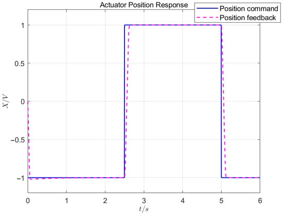
Figure 6.
Position control effect in dual-redundancy master-master working mode.
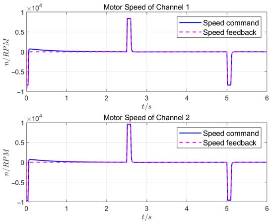
Figure 7.
Motor speed control effect in dual-redundancy master-master working mode.
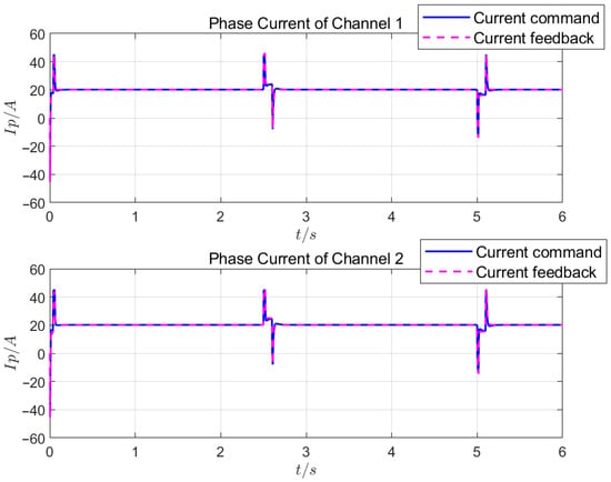
Figure 8.
Motor phase current control effect in dual-redundancy master-master working mode.
Under Test 2, the response curves of the position loop, speed loop, and current loop are shown in Figure 9, Figure 10, and Figure 11, respectively.
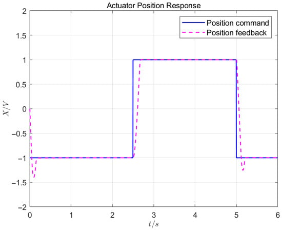
Figure 9.
Position control effect in dual-redundancy master-standby working mode.
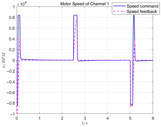
Figure 10.
Moto speed control effect in dual-redundancy master-standby working mode.
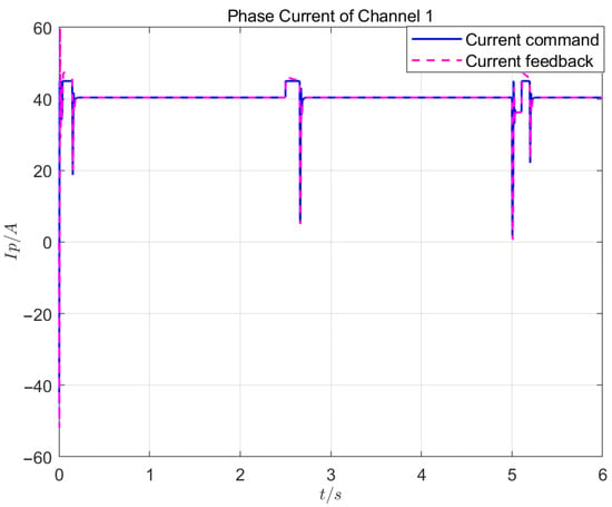
Figure 11.
Motor phase current control effect in dual-redundancy master-standby working mode.
5.2.3. Result Analysis
Test 1 shows that, when using the control algorithm designed in this study, the position, speed, and current loops effectively suppressed external disturbances and achieved precise tracking, with the position control error not exceeding 0.02 mm. Based on the influence of the speeds and the phase currents of the two channels, the synchronization consistency of the two master-master channels was excellent, with a position synchronization period below 3 ms. The load-balancing control had a high consistency, with an inconsistency rate below .
When the same load was applied, a comparison of the Test 1 and Test 2 results showed that the master-master working mode had a position response time of 0.15 s, a response speed that reached 8300 rpm, and a steady-state current of 20 A. The master-standby working mode had a position response time of 0.19 s, a maximum response speed of 7900 rpm, and a steady-state current of 40 A. In terms of the response speed, motor heating, etc., the master-master working mode had obvious advantages over the master-standby working mode.
To further highlight the contribution of the proposed ASMC and improved ADRC algorithms, an additional comparison with the basic EHA system (without ASMC/ADRC, and only adopting simple PI control; consistent with the classical PI-based control framework mentioned in Section 1 for early flight control actuation systems) is supplemented, with the key performance metrics shown in Table 4.

Table 4.
Performance comparison of different control schemes.
As shown in Table 4, compared with the basic EHA with only PI control, the master-master mode (with the proposed algorithms) reduced the position control error by 75%, shortened the position response time by 46.4%, and improved the load distribution accuracy by 15 percentage points. Even the master-standby mode (with the proposed algorithms) outperformed the basic EHA in all metrics. This fully verifies that the integration of ASMC (enhancing the speed loop robustness) and improved ADRC (strengthening the position loop disturbance rejection) effectively compensates for the shortcomings of traditional PI control (e.g., a poor anti-disturbance ability and a low synchronization accuracy, as mentioned in Section 1). Additionally, the “position synchronization-current balancing” cooperative strategy further amplifies the performance advantages in the master-master mode.
6. Conclusions
In order to meet the requirements of high reliability, a high dynamic response, and high-precision control for advanced aircraft actuation systems, this study developed master-master working mode control technology for dual-redundancy EHA systems. A current loop-decoupling technology was designed based on vector control, and the robustness of the speed loop and the disturbance rejection capability of the position loop were improved by combining ASMC and improved ADRC. A two-level collaborative control strategy of “position synchronization-current balancing” based on the CCC strategy is proposed to solve the problems of synchronization error accumulation and load imbalance in the master-master mode. The experimental results show that the position loop control error was below ±0.02 mm and the load distribution accuracy was improved to more than , meeting the design requirements of advanced aircraft. This study’s results provide important technical support for engineering applications of power-by-wire flight control systems in advanced aircraft.
Author Contributions
Conceptualization, Y.L., X.B., and R.W.; methodology, X.B. and Z.W.; software, X.B.; validation, Z.W. and R.W.; formal analysis, X.B.; investigation, Y.L. and R.W.; resources, Y.L. and X.B.; data curation, Y.L.; writing—original draft preparation, X.B.; writing—review and editing, Y.L. and R.W.; visualization, X.B.; supervision, Z.W.; project administration, Y.L. All authors have read and agreed to the published version of the manuscript.
Funding
This research received no external funding.
Data Availability Statement
The data presented in this study are available from the corresponding author upon request. The data are not publicly available due to institutional privacy restrictions.
Conflicts of Interest
The authors declare no conflicts of interest.
References
- Ke, Y.; Li, Y.; Cao, Y.; Zhang, X. Research on model-based safety analysis of flight control system. Syst. Eng. Electron. 2021, 43, 3259–3265. [Google Scholar]
- Xing, X.; Luo, Y.; Han, B.; Qin, L.; Xiao, B. Hybrid Data-Driven and Multisequence Feature Fusion Fault Diagnosis Method for Electro-Hydrostatic Actuators of Transport Airplane. IEEE Trans. Ind. Informat. 2025, 21, 3306–3315. [Google Scholar] [CrossRef]
- Bae, J. A Review of Electric Actuation and Flight Control System for More/All Electric Aircraft. In Proceedings of the 24th International Conference on Electrical Machines and Systems (ICEMS), Gyeongju, Republic of Korea, 31 October–3 November 2021; pp. 1943–1947. [Google Scholar]
- Robbins, D.; Bobalik, J.; Stena, D.; Plag, K.; Rail, K.; Wal, K. F-35 Subsystems Design, Development, and Verification. In Proceedings of the Aviation Technology, Integration, and Operations Conference, Atlanta, GA, USA, 25–29 June 2018; pp. 365–398. [Google Scholar]
- Wiegand, C. F-35 Air Vehicle Technology Overview. In Proceedings of the Aviation Technology, Integration, and Operations Conference, Atlanta, GA, USA, 25–29 June 2018; pp. 1–28. [Google Scholar]
- Guan, L.; Lian, W. Review on Electro-Hydrostatic Actuation Technology of Aircraft Flight Control Actuation System. Meas. Control Technol. 2022, 41, 1–11. [Google Scholar]
- Tai, M.; Yu, H.; Zhao, Z.; Liu, Z.; Zhu, Y. Research on Control of Double-pump Electro-Hydrostatic Actuator (EHA). Aircr. Des. 2023, 43, 31–35. [Google Scholar]
- Yang, X.; Wang, X.; Wang, S.; Puig, V. Switching-based adaptive fault-tolerant control for uncertain nonlinear systems against actuator and sensor faults. J. Franklin Inst. 2023, 360, 11462–11488. [Google Scholar] [CrossRef]
- Dills, P.; Dawson-Elli, A.; Gruben, K.; Adamczyk, P.; Zinn, M. An Investigation of a Balanced Hybrid Active-Passive Actuator for Physical Human-Robot Interaction. IEEE Robot. Autom. Lett. 2021, 6, 5849–5856. [Google Scholar] [CrossRef]
- Fu, J.; Maré, J.C.; Fu, Y. Modelling and simulation of flight control electromechanical actuators with special focus on model architecting, multidisciplinary effects and power flows. Chin. J. Aeronaut. 2017, 30, 47–65. [Google Scholar] [CrossRef]
- Huang, L.; Yu, T.; Jiao, Z.; Li, Y. Research on Power Matching and Energy Optimal Control of Active Load-Sensitive Electro-Hydrostatic Actuator. IEEE Access 2021, 9, 51121–51133. [Google Scholar] [CrossRef]
- Ahn, K.; Nam, D.; Jin, M. Adaptive Backstepping Control of an Electrohydraulic Actuator. IEEE/ASME Trans. Mechatron. 2014, 19, 987–995. [Google Scholar] [CrossRef]
- Bai, L.; Cui, N.; He, M.; Zhang, Y. Research on Electro-hydrostatic Actuator(EHA) Load Matching Method. Hydraul. Pneum. Seals 2022, 4, 59–65. [Google Scholar]
- Qiu, Y.; Li, Y.; Liu, Y.; Wang, Z.; Liu, K. Observer-based robust optimal control for helicopter with uncertainties and disturbances. Asian J. Control 2023, 25, 3920–3932. [Google Scholar] [CrossRef]
- Sui, H.; Liu, W.; Zhou, H. Design of servo control system based on fuzzy adaptive PI. J. Hebei Acad. Sci. 2024, 41, 49–54. [Google Scholar]
- Lin, Y.; Shi, Y.; Burton, R. Modeling and Robust Discrete-Time Sliding-Mode Control Design for a Fluid Power Electrohydraulic Actuator (EHA) System. IEEE/ASME Trans. Mechatron. 2013, 18, 110. [Google Scholar] [CrossRef]
- Ali, S.; Christen, A.; Begg, S.; Langlois, N. Continuous–Discrete Time-Observer Design for State and Disturbance Estimation of Electro-Hydraulic Actuator Systems. IEEE Trans. Ind. Electron. 2016, 63, 4314–4324. [Google Scholar] [CrossRef]
- Li, Z.; Zhang, Q.; An, J.; Liu, H.; Sun, H. Cross-coupling control method of the two-axis linear motor based on second-order terminal sliding mode. J. Mech. Sci. Technol. 2022, 7, 1485–1495. [Google Scholar] [CrossRef]
- Fan, D.; Liu, H.; Su, Y. Integral robust collaborative control of hydraulic servo system based on cross-coupling. IEEE Trans. Ind. Electron. 2025, 53, 81–87. [Google Scholar]
- Yao, J.; Cao, X.; Zhang, Y.; Li, Y. Cross-coupled fuzzy PID control combined with full decoupling compensation method for double cylinder servo control system. J. Mech. Sci. Technol. 2018, 32, 2261–2271. [Google Scholar] [CrossRef]
- Qi, H.; Teng, Y. Force equalization control for dual-redundancy electrol-hydrostatic actuator. J. Beijing Univ. Aeronaut. Astronaut. 2017, 43, 270–276. [Google Scholar]
- Zhou, F.; Liu, H.; Zhang, P.; Ouyang, X.; Xu, L.; Ge, Y.; Yao, Y.; Yang, H. High-Precision Control Solution for Asymmetrical Electro-Hydrostatic Actuators Based on the Three-Port Pump and Disturbance Observers. IEEE/ASME Trans. Mechatron. 2023, 28, 396–406. [Google Scholar] [CrossRef]
- Hong, H.; Gao, B.; Li, J. Sliding Mode-PID Control for Aircraft Electro-Hydrostatic Actuator. Civ. Aircr. Des. Res. 2023, 131, 42–46. [Google Scholar]
- Krishnan, R. Permanent Magnet Synchronous and Brushless DC Motor Drives; CRC Press: Boca Raton, FL, USA, 2010; pp. 182–279. [Google Scholar]
- Khalil, H. Nonlinear Systems, 3rd ed.; Pearson Education: London, UK, 2017; pp. 552–575. [Google Scholar]
- Han, J. Auto-disturbances-rejection controller and it’s applications. Control Decis. 1998, 13, 19–23. [Google Scholar]
- Han, J. From PID to Active Disturbance Rejection Control. IEEE Trans. Ind. Electron. 2009, 56, 900–906. [Google Scholar] [CrossRef]
Disclaimer/Publisher’s Note: The statements, opinions and data contained in all publications are solely those of the individual author(s) and contributor(s) and not of MDPI and/or the editor(s). MDPI and/or the editor(s) disclaim responsibility for any injury to people or property resulting from any ideas, methods, instructions or products referred to in the content. |
© 2025 by the authors. Published by MDPI on behalf of the International Institute of Knowledge Innovation and Invention. Licensee MDPI, Basel, Switzerland. This article is an open access article distributed under the terms and conditions of the Creative Commons Attribution (CC BY) license (https://creativecommons.org/licenses/by/4.0/).