Abstract
In recent years, abrasive waterjet machining has emerged as a promising machining technique for the machining of composites because of its non-thermal nature. In the present study, the effect of machining parameters on the quality of machining has been studied and the process parameters have been optimized to machine jute-fiber-reinforced polymer composites. The design of the experiment was used to predict the combination of the input parameters for L27 experiments. Taguchi and response surface methodology (RSM) techniques were employed to analyze the experimental data and identify the optimum combination of process parameters to achieve as little delamination as possible. The results indicate that an increase in the values of the parameters traverse speed and abrasive mass flow rate leads to an increase in the damage obtained. However, an increase in the value of the parameter stand-off distance minimizes the damage produced. To achieve minimum delamination, the optimum combination of input parameters is obtained through Taguchi and RSM. For the present experimental condition, to achieve minimum delamination, the parameter traverse speed should be set at 20 mm/min, the stand-off distance should be 4 mm, and the abrasive flow rate should be set at 0.25 kg/min. The results confirm that the optimum combination of parameters obtained through both approaches is similar. This investigation results indicated a significant improvement in the cutting quality with reduced damage, achieved through the optimized process parameters. For the considered range of parameters, graphs are plotted such that any intermediate values can be anticipated within the considered range without performing any further experiments. The present work signifies the effect of fiber orientation on delamination.
1. Introduction
In recent years, polymer-based composites have gained favor over traditional materials because they provide improved mechanical, physical, and thermal qualities. High temperatures are generated during the conventional treatment of composites. Additionally, cutting forces create a variety of problems, including tool wear, fiber extraction, delamination, and surface failure, since these materials are non-homogeneous and anisotropic [1]. Abrasive waterjet machining (AWJM) is a very accurate machining process that uses a high-pressure waterjet along with abrasive particles as the cutting agents. AWJM is capable of machining various materials, including composites. This machining method has become popular because of its non-thermal process, material versatility, high accuracy, minimum material wastage, reduced tool wear and reduced dust. The quality of AWJM depends on several machining parameters, such as abrasive type and size, abrasive mass flow rate, nozzle design, water pressure, stand-off distance, cutting speed, which is popularly known as traverse speed, the properties of the materials to be machined, the precision and accuracy of the CNC machine, etc. AWJM is a suitable machining or cutting method for fiber-reinforced composites because it does not produce a heat-affected zone, generates very little residual stress, and causes minimum tool wear [2]. In spite of these advantages, damage occurs during the machining process. Many machining input parameters significantly affect delamination. An enormous number of research works have been conducted to analyze and minimize this damage through various approaches. H Ho-Cheng [3] attempted to study delamination through an analytical approach. This approach includes fracture mechanics with plate theory to describe the delamination mechanism that occurs during AWJM of composites. The researchers found a good agreement between predicted and experimental values during the initial stages of waterjet machining. They also developed delamination prediction models. Shanmugam et al. [4] predicted that delamination would occur due to water penetration into the crack tips, which is generated by the shock wave input prediction model based on the energy-conserving approach.
Murat Demiral et al. [5] conducted research on the machining of CFRP composites using both abrasive waterjet machining and pure waterjet machining. They compared the two methods and developed a 3D finite element model for abrasive waterjet machining using ABAQUS software (ABAQUS Standard version, https://www.3ds.com/products-services/simulia/products/abaqus/abaqusstandard/). J. Schwartzentruber et al. [6] studied delamination during abrasive waterjet machining of a carbon fiber–epoxy laminate. The researchers produced a numerical model to predict the effect of process parameters and found that traverse speed, mixing tube size, and abrasive flow rate had the most significant impact on delamination. Hom Nath Dhakal et al. [7] conducted a study on the delamination that occurs in hybrid carbon–flax and carbon-fiber-reinforced composites when abrasive waterjet machining was carried out and contributed to the research efforts in this area. Azmir and Hussein Mohammad Ali Ibraheem [8,9] developed a numerical optimization model aimed at minimizing delamination during AWJM of GFRP composites. While machining composite materials, the quality of the machining, such as cutting-edge kerf taper, machined surface roughness, and damage, is dependent on many input parameters such as water pressure, nozzle geometry, stand-off distance, cutting speed, abrasive mass flow rate, reinforced fiber orientation, etc. Therefore, a vast number of researchers have carried out work in this field to understand the effect of each of these process parameters on the quality of machined surfaces. S Vigneshwaran et al. [10] contributed by publishing a review paper on AWJM of fiber-reinforced polymer composites; they have provided a lot of information on the effects of various parameters on the delamination and surface roughness. S. Xiao et al. [11] worked to estimate the effect of multi-pass cutting over the delamination during AWJM of CFRP composites and noticed that due to multi-pass cutting, the delamination and the kerf qualities are improved to a larger extent. Ajit Dhanawade et al. [12] conducted AWJM experiments on carbon-fiber-reinforced polymer composites and optimized the process parameters to minimize the roughness of the machined surface. They developed a mathematical model based on experiments to reduce the surface roughness. Ravi Kant et al. and Kechagias J. et al. [13,14] conducted AWJM on EN-31 steel and Trip steel in order to predict the effect of process parameters on the surface roughness. Kechagias applied Taguchi design for quality characterization. A review article on the AWJM of various materials was published by Anusha Kale et al. [15]. In this publication, they gave complete coverage regarding the impact of parameters such as transverse speed, stand-off distance, water pressure, and abrasive flow rates on the material removal rate and surface roughness. ANOVA was conducted to analyze the experimental results. J. Wang [16] conducted worked on the AWJM of composite material and examined cutting performance and erosive process during machining. Through his research, he discovered that there are two types of kerfs: through cuts and non-through cuts. Through cuts are obtained when higher water pressure and low traverse speed are used, and non-through cuts are generated when the jets are unable to cut the specimen. He also identified that, depending on the energy level of the jet, the AWJ machined surface has two regions: the upper region and the lower region. They claimed that delamination only occurs in non-through regions. Researchers Prasanna et al. [17] conducted a study on the abrasive waterjet machining of hybrid composites made with Bismaleimide. They investigated how the process parameters affected the kerf angle and used the Taguchi central composite design method to plan their experiments. Their findings showed that the delamination was significantly influenced by the abrasive mass flow rate. While machining the composite material using the abrasive waterjet machine, if the machining parameters are fixed at the optimum level, then the nozzle wear rate, machined surface roughness, and delamination will be at minimum levels. Due to this reason, researchers like Jeykrishnan et al., K. Ravikumar et al., and M. Manoj et al. [18,19,20] worked to obtain the optimum combination of process parameters through various optimization techniques such as traditional analysis, response surface methodology, and multi-response optimization techniques. Researchers J. Wang et al., E. Lemma et al., and Angelos P. Markopoulos et al. [21,22,23]. worked to optimize the process parameters through the kerf–taper compensation technique, the nozzle oscillation technique, artificial neural network modeling, etc.
In the literature, it appears that there has been little exploration into the impact of machining parameters on delamination when using abrasive waterjet machining on jute-fiber-reinforced polymer composites. Furthermore, it seems that the Taguchi and response surface methodology approaches have not been utilized to optimize the waterjet machining process for jute–epoxy composites. In this present work, an attempt has been made to optimize the process parameters using the Taguchi and response surface methodology approaches to optimize AWJM of jute–epoxy composites.
2. Methods and Methodology
2.1. Material Preparation
The hand layup method is one of the simplest and earliest methods for creating fiber-reinforced composites. The same procedure was used in this study to produce composite specimens in the lab with a 45° fiber orientation. General-purpose epoxy resin, with the commercial name BISPHENOL-A (BPA), manufactured by Huntsman polymers, purchased from Renuka Enterprises, Mumbai, India, is the matrix material, and Methyl Ethyl Ketone Peroxide is the hardener. Jute fiber mats were cropped to the necessary size to start the preparation of composite samples. To maintain the desired amount of volume fraction, measured quantities of fiber mat and resin are used. The volume fraction of jute fiber is 35% by weight and the epoxy volume is 65% by weight. The releasing agent was used after cleaning the supporting steel plates. The first fiber mat with an inclination of 45° is spread on the plate and coated with resin. This stacking process is carried out again, maintaining a 45° fiber orientation, until all of the fiber mats that were collected are stacked. After stacking is complete, the top plate is put in place, the fiber and resin are covered in polythene paper, and the entire assembly is then placed in a heat-pressing machine for 48 h to remove any trapped air and to cure. After curing, the composite plate is removed and the surplus fibers are trimmed off from all four sides. Figure 1 shows the various stages of the hand layup process used to create the specimen.
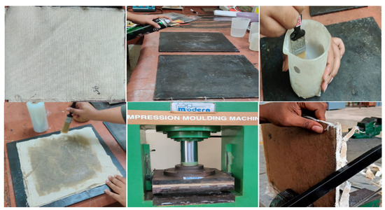
Figure 1.
Steps followed to prepare the jute fiber reinforced polymer composite.
2.2. Machining Process
Machining was carried out on the CNC-controlled 5-axis abrasive waterjet cutting machine (Omax Corp, Kent, WA, USA: model no. MAXIEM1515) by mounting the specimens securely on cardboard with double-sided glue tape. Traverse speed (TS), standoff distance (SOD), and abrasive mass flow rate (MFR) were the variable input parameters. Three levels of variation were selected for each parameter. The traverse speed levels are 20, 25, and 30 mm/min, the stand-off distances were taken as 2, 3, and 4 mm, and the mass flow rates are chosen as 0.25, 0.3, and 0.35 kg/min, respectively. The machining parameters were selected on the basis of previous research works carried out by many researchers; researchers have found that the considered range gives better machining properties on jute epoxy composites [24]. Even though the machine is frequently checked and maintained, to ensure accurate machining, prior to starting the machining process, the setup is checked for several parameters. The nozzle and the orifice were inspected to confirm that there was no wear or damage. The abrasive flow rate was measured and adjusted as needed. Water pressure was measured and fixed to the considered level. The traverse speeds for various levels were measured and adjusted according to the intended values. The stand-off distance values were checked and set with precision. The abrasive mixing ratios were carefully measured and adjusted to ensure proper mixing with water. To ensure the precision of the cuts, the cutting depth was calibrated and adjusted to suit the test specimen. Once all parameters were confirmed and adjusted to desired values, test cuts were conducted to further confirm the precise cutting of the specimen. While machining, some safety measures were taken, such as wearing safety goggles, face shields, hearing protection to avoid damage from the noise, and gloves and safety protective clothing were worn to avoid abrasive splash back. The abrasive hose was inspected and we confirmed that there was no damage or leakage. Adequate ventilation was provided to the machining area and it was completely shielded from human entry during machining.
In this experimental work, garnet was used as the abrasive material for waterjet machining. Almandine, a type of garnet known for its hardness and sharp edges, was used in this work due to its popularity and cost-effectiveness. It can cut through various materials like metals, ceramics, and composites. The hardness of Almandine garnet falls between 7.5–8.0 on the Mohs scale. Different mesh sizes ranging from coarse 50 mesh to very fine 230 mesh are available. A mesh size 80 with garnet was used in this machining process. Mesh 80 garnet is the most commonly used and is effectively abrasive in waterjet machining. Garnet is generally non-toxic and non-hazardous; hence, it does not pose immediate risks to the environment or human health compared to several other abrasive materials. It can be reused several times in waterjet machining processes, reducing the need for new garnets and minimizing waste. When used in abrasive waterjet machining, garnets cleanly cut materials without producing hazardous dust or fumes. The jet angle was maintained at 90° on the workpiece, and the waterjet pressure was maintained at a constant 200 MPa. The plate was cut into 27 pieces measuring 50 mm long to measure the delaminated area (DA) by varying the parameters. The machining setup is shown in Figure 2. The output was measured as the delamination area in mm2. The delamination area was measured by taking an image of each hole produced before the start of longitudinal machining.
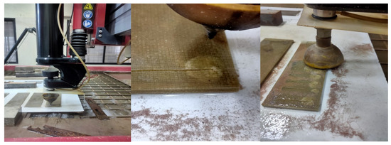
Figure 2.
Abrasive waterjet machining of jute-fiber-reinforced polymer composite.
2.3. Measurement of Delamination
The damage caused during machining was measured in terms of the damaged area. In the present experimentation, a through hole was drilled before starting the longitudinal machining, as shown in Figure 3. The area around the hole that was damaged due to machining was measured and considered as the delaminated area. In order to measure the delaminated area accurately, ImageJ software (ImageJ version 1.53t) was used. Some samples of the delamination area, measured using ImageJ software, are presented in Figure 3.
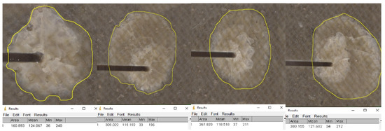
Figure 3.
Estimation of delamination area using ImageJ software.
3. Results and Analysis
Using the design of experiment method, the necessary number of experiments was determined. The final parameter combination for each experiment was determined using the Taguchi L27 array. The considered range for each input variable is presented in Table 1 and the L27 experiments list and the estimated delamination (average of two values) details are presented in Table 2.

Table 1.
Input variables and their levels.
Table 2.
Taguchi L27 array used for experimentation.
3.1. Regression Equation for the Delamination
The regression equation for delamination was obtained and is provided in Equation (1). While obtaining this regression equation, an assumption was made that the relationship between the independent variable and the dependent variable is linear (Linearity Assumption). With the help of a regression equation, we can mathematically estimate the delamination value for the various levels of the input parameters. The regression table is presented in Table 3. As per the table, the parameter abrasive mass flow rate exhibits a highly significant effect on the delamination.
Table 3.
Regression table for DA versus TS, SOD, and MFR.
Regression Analysis: DA versus TS, SOD, MFR.
The regression equation is:
DA = −88.9 + 0.381 TS − 3.72 SOD + 5.84 MFR
The normal probability plot shows that there are negligible outlier points, but most of them are collinear which confirms the suitability of the model.
The distribution of the result from the neutral line is shown on the residual v/s observation order plot. The graphic shows that the distribution is about equal on both sides of the line. Thus, it is demonstrated that the experiments carried out are appropriate for the problem under consideration. Figure 4 displays the residual plot and the normal probability plot.
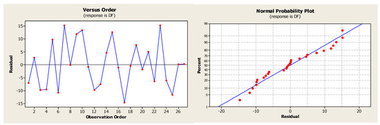
Figure 4.
Normal probability plot and residual plot.
3.2. Main Effect Plots for Data Means and Signal-to-Noise Ratio
The gradient line on the main effect plot depicts the influence of that parameter on the result. The more the line is inclined, the higher the influence on the output parameter. In this particular experiment, the parameter abrasive mass flow rate is showing a steeper slope. The delamination is thus most affected by this particular input parameter when compared to other input factors. Delamination increases more drastically with even a little variation in abrasive mass flow rate. Following the mass flow rate, the standoff distance shows a moderate shift, indicating a moderate impact on the delamination. The parameter traverse speed indicates the least effect by showing the smaller slope. Consequently, a wider range of settings for this parameter is possible. Figure 5 shows the main effect plot for the signal-to-noise (S/N) and data means.
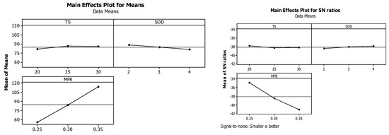
Figure 5.
Main effect plots for data means and SN ratio.
3.3. Interaction Plots for Data Means and Signal-to-Noise Ratio
Figure 6 shows an interaction plot for data means and S/N ratio. The figures show that the parameters traverse speed and standoff distance do interact to some extent. Hence, there are some combined effects of these parameters on delamination. The total effect will be greater when there is more interaction between the two parameters. Between the parameters of the traverse speed and standoff distance, and traverse speed and abrasive mass flow rate a very small interaction is noticed. There is no evidence of interaction of mass flow rate with traverse speed and stand-off distance.
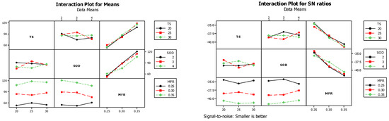
Figure 6.
Interaction plots for data mean and S-N ratio.
3.4. Analysis of Variance and Response Tables
Table 4 displays the current experiment’s ANOVA table. The ANOVA is carried at 95% confidence level (α value). The table makes it evident that the abrasive mass flow rate has the greatest influence on delamination. Therefore, even minor changes to this particular input parameter cause a sharp increase in delamination. As a result, extreme caution should be used when modifying this value. The standoff distance is the factor that significantly influences delamination following the abrasive mass flow rate. Hence, the impact of this on the output is moderate. As a result, this parameter can be altered somewhat to suit our needs. Traverse speed is the parameter that has a negligible impact on the delamination. Therefore, even significant modifications in this parameter have little or no impact on the delamination. Therefore, within the range, this parameter can be fixed at any value.
Table 4.
Analysis of variance for DF, using adjusted SS for tests.
Table 5 displays the Taguchi response table for the data means. The data presented in this table are identical to those in an ANOVA. The parameter with the highest ranking as determined by the order in which the input parameters were given is the abrasive mass flow rate, which indicates that it has the most impact on delamination. In parallel with the abrasive mass flow rate, the standoff distance and traverse speed are also considered.
Table 5.
Taguchi response table for data means.
Delamination is the main defect that occurs during the machining of composite materials by any method. While machining using AWJ, this will occur on both the top and bottom sides of the composites. Previous works reported that, in AWJM, the delamination is commenced by the shock waves produced by the waterjet. Hence, the delamination on the top is always greater than that on the bottom side. As the abrasives approach the upper surface of the composites, they possess high cutting energy. However, as the jet propagates towards the downside, these abrasive particles continuously lose their cutting energy. Experimental studies have proven that delamination is a phenomenon that cannot be avoided when using AWJ to start a cut at a position within a workpiece, and such a phenomenon occurs mainly in the initial cutting stage. It does not seem to pose a major problem as the cutting continues if the process parameters are selected properly. Hence, in the present experimentation, the delamination initiated on the hole generated before the commencement of cutting is measured. The delamination measured here is the damage caused to the hole when the cutting is initiated; therefore, it is measured in the unit of the damaged area.
From the experimentation results, it is clear that the amount of abrasive mass flow rate has a major effect on the delamination and as the abrasive mass flow rate increases, the delamination increases. The reason for this may be that, when the number of abrasive particles increases beyond the optimum value, the particles begin to impact each other during the flow due to the large number of particles present per unit volume. This impact changes the movement of the abrasive particles, and the movement becomes turbulent. This turbulence leads to more deviation of the cutting jet which increases the damaged area. When the standoff distance escalates, the velocity as well as cutting energy of the abrasive material are reduced by the time the jet reaches the bottom surface. Hence, less impact force is applied to the lower side layers of the composites which leads to a cutting rather than a piercing or shearing action. Hence, as the standoff distance increases, the pushdown delamination decreases in the machining of composite material. But there is an optimum value for this; beyond this value, it starts increasing due to the larger jet diversion. As the cutting speed increases, the cutting area per unit time increases, which leads to less cutting action and increases the penetration of the abrasive materials through the composites. Hence, as the cutting speed increases, there is an increment in the delamination.
3.5. Optimization through Optimization Plot
Plotting the optimization plot will yield the optimal set of process parameters for any output parameter. The optimization plot obtained from the response surface methodology is the one that will provide the combination of various levels of each parameter within the considered limit. Figure 7 shows the plot that was created for the current experiment to minimize damage during the machining process. According to the plot, one should use the following combination to achieve the least amount of delamination. The standoff distance should be at level 3 (4 mm), the traverse speed should at level 1 (20 mm/min), and the abrasive mass flow rate should be at level 1 (0.25 kg/min).
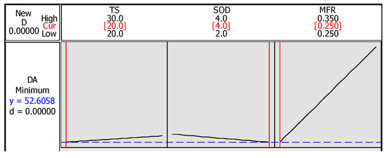
Figure 7.
Optimization plot to achieve minimum delamination.
3.6. Optimization Using Contour Plots
When the other parameters are held constant, contour plots display the levels of response parameter variation with the variation of two parameters. Figure 8, Figure 9 and Figure 10 show contour charts for various combinations of parameters. When the parameter abrasive mass flow rate is held constant, the variable levels of delamination with regard to changes in traverse speed and standoff distance are shown on the graph in Figure 8. We can choose the set of two values from the graph that results in less delamination. For instance, according to the graph, if higher standoff distance and a slower traverse speed are maintained, then the amount of delamination produced will be reduced when the constant abrasive mass flow rate is set at 0.25 kg/min. As a result, level 3 for stand-off distance and level 1 for traverse speed must be chosen.
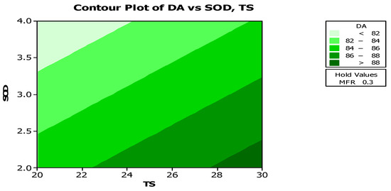
Figure 8.
Contour plot for DA vs. SOD and TS.
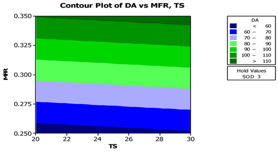
Figure 9.
Contour plot for DA vs. MFR and TS.
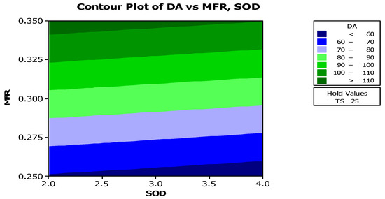
Figure 10.
Contour plot for DA vs. MFR and SOD.
Similarly to Figure 8, Figure 9 shows reduced delamination at a lower abrasive mass flow rate and low speeds with the third parameter stand-off distance remaining constant at 3 mm. Therefore, we must choose traverse speed and abrasive mass flow rate at level 1. Similarly to Figure 9, Figure 10 depicts decreased delamination at level 1 traverse speed and level 3 standoff distance.
If the levels obtained from different graphs to achieve the lower delamination are combined, it would be TS = 20 mm/min, SOD = 4 mm, and MFR = 0.25 kg/min.
3.7. Prediction of Intermediate Values of DA
For the current experiment, graphs are plotted using optimization plots to anticipate the intermediate values of the delamination within the considered limits for the input parameters. Examples of these graphs are shown in Figure 11 and Figure 12. By entering the intermediate values of input parameters in the optimization plot, intermediate values of DA are acquired. Plots are created after sufficient data have been gathered.
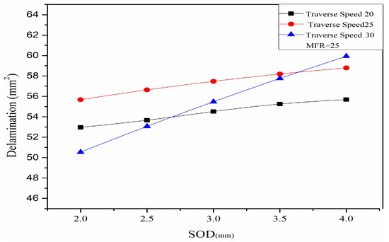
Figure 11.
Graphs representing delamination when MFR is 0.25 kg/min.
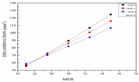
Figure 12.
Graphs for delamination when traverse speed is 25 mm/min.
These plots have the benefit of allowing us to retrieve any intermediate values without using any software. Figure 11 shows the change of DA for the full range of input parameters for the 0.25 kg/min mass flow rate. When the traverse speed is held constant at 25 mm/min, we may obtain the DA from Figure 12 for any intermediate value of the input parameters. In a similar way, by keeping the input parameters at various levels, we may produce the graphs and obtain the DA value.
3.8. Prediction of Fiber Orientation Influence on Delamination
In order to predict the effect of reinforced fiber orientation on delamination, the same set of experiments was conducted on two different specimens reinforced with jute fibers in different orientations. For the first sample, the orientation was held at 45° to the cutting direction, and for the second sample, the orientation was fixed at 90° to the cutting direction. The results obtained for each experiment are given in Table 6 and the same is presented in graph format in Figure 13. The figure confirms that except for very few cases, the delamination is always greater for 90° orientation than for 45° orientation, which signifies the effect of fiber orientation on delamination.
Table 6.
DA values obtained for 45° and 90° fiber orientation.
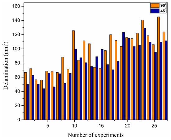
Figure 13.
Measured delamination values for 45° and 90° fiber orientation.
Jute–epoxy composites have increasingly wide applications in the aerospace industry to produce aircraft cabin panels and aircraft interior components. In the automotive field, they are being used to manufacture door panels and various structural components. In this way, these jute–epoxy composites are finding applications in various fields such as the marine industry, the sporting goods industry, the electronics industry, the furniture and home decoration industry, etc. Optimized abrasive waterjet machining can be used in all these fields to cut and shape the composites precisely.
The optimization methods followed in this work can be further extended to optimize the process parameters to minimize the roughness of the machined surfaces to enhance the machining properties. This principle of optimization can be implemented to optimize the process parameters by varying parameters like water pressure and varying reinforced fiber volume fraction of the composite.
4. Conclusions
The obtained results clearly demonstrate that abrasive waterjet machining is an appropriate method for machining jute–epoxy fiber composites.
From the results, it is also proven that the delamination phenomenon in the machining of composite materials was unavoidable in the present experimental conditions. When considering input parameters, it is evident that the parameter of abrasive mass flow rate (MFR) has the greatest influence on the delamination process. Following this, the stand-off distance (SOD) parameter has a moderate effect on the output parameter. The traverse speed (S) parameter has the least influence.
From the output of the work, it is evident that minimum delamination values will be achieved when the input parameters are fixed as follows:
- Traverse speed (TS) of 20 mm/min;
- Stand-off distance (SOD) of 4 mm;
- Abrasive mass flow rate (MFR) of 0.25 kg/min.
Under the selected conditions, the obtained value of DA is 52.605 mm2.
Since composites are very anisotropic in nature, standardizing the experiment procedure is not feasible. Hence, an optimum combination of process parameters obtained to minimize the delamination is only for the present machining condition. The optimum combination of parameters obtained from the Taguchi and response surface methodology techniques is similar. The results also confirm that the reinforced fiber orientation has a significant effect on delamination.
Further research work can be taken up to find out the exact relationship between delamination and fiber orientation. Future work can carryout to predict the fiber best which obtains minimum delamination.
Author Contributions
Writing—review and editing, B.R.N.M.; software, S.R.U.; Formal Analysis, N.N.; Methodology, S.R.P.; Validation, S.N.S. All authors have read and agreed to the published version of the manuscript.
Funding
This research received no external funding.
Institutional Review Board Statement
Not applicable.
Informed Consent Statement
Not applicable.
Data Availability Statement
The data presented in this study are available on request from the corresponding author.
Conflicts of Interest
The authors declare no conflict of interest.
References
- Perek, A.; Radomska-Zalas, A.; Fejdek-Beida-Frank Pude, A. Process optimization by applying the response surface methodology (rsm) to the abrasive suspension water jet cutting of phenolic composites. Facta Univ. Mech. Eng. 2022, 1, 1–16. [Google Scholar]
- Ramulu, M.; Arola, D. Water jet and abrasive water jet cutting of unidirectional graphite/epoxy composite. Composites 1993, 24, 299–308. [Google Scholar] [CrossRef]
- Ho-Cheng, H. A failure analysis of water jet drilling in composite laminates. Int. J. Mach. Tools Manuf. 1990, 30, 423–429. [Google Scholar] [CrossRef]
- Shanmugam, D.K.; Nguyen, T.; Wang, J. A study of delamination on graphite/epoxy composites in abrasive water jet machining. Compos. Part A Appl. Sci. Manuf. 2008, 39, 923–929. [Google Scholar] [CrossRef]
- Demiral, M.; Abbassi, F.; Saracyakupoglu, T.; Habibi, M. Damage analysis of a CFRP cross-ply laminate subjected to abrasive water jet cutting. Alex. Eng. J. 2022, 61, 7669–7684. [Google Scholar] [CrossRef]
- Schwartzentruber, J.; Papini, M.; Spelt, J.K. Characterizing and modeling delamination of carbon-fiber epoxy laminates during abrasive waterjet cutting. Compos. Part A Appl. Sci. Manuf. 2018, 112, 299–314. [Google Scholar] [CrossRef]
- Dhakal, H.N.; Ismail, S.O.; Ojo, S.O.; Paggi, M.; Smith, J.R. Abrasive water jet drilling of advanced sustainable bio-fibre-reinforced polymer/hybrid composites: A comprehensive analysis of machining-induced damage responses. Int. J. Adv. Manuf. Technol. 2018, 99, 2833–2847. [Google Scholar] [CrossRef]
- Azmir, M.A.; Ahsan, A.K.; Rahmah, A. Effect of abrasive water jet machining parameterson aramid fibre reinforced plastics composite. Int. J. Mater. Form. 2009, 2, 37–44. [Google Scholar] [CrossRef]
- Ibraheem, H.M.A.; Iqbal, A.; Hashemipour, M. Numerical optimization of the hole making in GFRP composites using abrasive water jet machining process. J. Chin. Inst. Eng. 2015, 38, 66–76. [Google Scholar] [CrossRef]
- Vigneshwaran, S.; Uthayakumar, M.; Arumugaprabu, V. Abrasive Water Jet Machining of Fiber-Reinforced Composite Materials. J. Reinf. Plast. Compos. 2018, 37, 230–237. [Google Scholar] [CrossRef]
- Xiao, S.; Wang, P.; Gao, H.; Soulat, D. A Study of Abrasive Waterjet Multi-Pass Cutting on Kerf Quality of Carbon Fiber-Reinforced Plastics. Int. J. Adv. Manuf. Technol. 2019, 105, 4527–4537. [Google Scholar] [CrossRef]
- Dhanawade, A.; Kumar, P.; Kumar, S. Experimental Study on Abrasive Water Jet Machining of Carbon Epoxy Composite. Adv. Mater. Process. Technol. 2020, 6, 40–53. [Google Scholar] [CrossRef]
- Kant, R.; Dhami, S.S. Investigating Process Parameters of Abrasive Water Jet Machine Using EN31. Mater. Manuf. Process. 2021, 36, 1597–1603. [Google Scholar] [CrossRef]
- Kechagias, J.; Petropoulos, G.; Vaxevanidis, N. Application of Taguchi Design for Quality Characterization of Abrasive Water Jet Machining of TRIP Sheet Steels. Int. J. Adv. Manuf. Technol. 2012, 62, 635–643. [Google Scholar] [CrossRef]
- Kale, A.; Singh, S.K.; Sateesh, N.; Subbiah, R. A Review on Abrasive Water Jet Machining Process and Its Process Parameters. Mater. Today 2020, 26, 1032–1036. [Google Scholar] [CrossRef]
- Wang, J. Abrasive Waterjet Machining of Polymer Matrix Composites—Cutting Performance, Erosive Process and Predictive Models. Int. J. Adv. Manuf. Technol. 1999, 15, 757–768. [Google Scholar] [CrossRef]
- Iyer, N.P.; Kumar, N.A. Investigation of Abrasive water jet machining parameters of Bismaleimide composites. Mater. Manuf. Process. 2022, 37, 1642–1651. [Google Scholar] [CrossRef]
- Jeykrishnan, J.; Ramnath, B.V.; Vignesh, S.S.; Sridharan, P.; Saravanan, B. Optimization of Process Parameters in Abrasive Water Jet Machining/Cutting (AWJM) of Nickel Alloy Using Traditional Analysis to Minimize Kerf Taper Angle. Mater. Today 2019, 16, 392–397. [Google Scholar] [CrossRef]
- Ravikumar, K.; Sreebalaji, V.S.; Pridhar, T. Characterization and optimization of Abrasive Water Jet Machining parameters of aluminum/tungsten carbide composites. Measurement 2018, 117, 57–66. [Google Scholar] [CrossRef]
- Manoj, M.; Jinu, G.R.; Muthuramalingam, T. Multi Response Optimization of AWJM Process Parameters on Machining TiB2 Particles Reinforced Al7075 Composite Using Taguchi-DEAR Methodology. Silicon 2018, 10, 2287–2293. [Google Scholar] [CrossRef]
- Shanmugam, D.K.; Wang, J.; Liu, H. Minimisation of kerf tapers in abrasive waterjet machining of alumina ceramics using a compensation technique. Int. J. Mach. Tools Manuf. 2008, 48, 1527–1534. [Google Scholar] [CrossRef]
- Lemma, E.; Chen, L.; Siores, E.; Wang, J. Optimising the AWJ cutting process of ductile materials using nozzle oscillation technique. Int. J. Mach. Tools Manuf. 2002, 42, 781–789. [Google Scholar] [CrossRef]
- Vaxevanidis, N.M.; Markopoulos, A.; Petropoulos, G. Artificial neural network modelling of surface quality characteristics in abrasive water jet machining of trip steel sheet. J. Intell. Manuf. 2008, 19, 283–292. [Google Scholar]
- Kalirasu, S.; Rajani, N.; Rajesh, S.; Gopikumar, S.; Arunkumar, K.; Mukesh Vaidya, C.M. Surface Quality of Jute Fibre Reinforced Epoxy Composite by Abrasive Waterjet Machining. Int. J. Recent Technol. Eng. 2019, 8, 196–199. [Google Scholar]
Disclaimer/Publisher’s Note: The statements, opinions and data contained in all publications are solely those of the individual author(s) and contributor(s) and not of MDPI and/or the editor(s). MDPI and/or the editor(s) disclaim responsibility for any injury to people or property resulting from any ideas, methods, instructions or products referred to in the content. |
© 2023 by the authors. Licensee MDPI, Basel, Switzerland. This article is an open access article distributed under the terms and conditions of the Creative Commons Attribution (CC BY) license (https://creativecommons.org/licenses/by/4.0/).