Abstract
As a new type of bridge deck skin material, tiled laminates (TLs) are often subjected to bending actions in actual working conditions. This study employs a 3D progressive damage model (3D PDM) based on the Hashin damage criterion to investigate the influence of overlap configuration and inclination angle on the bending performance of tiled laminates in both elastic and non-linear stages through three-point bending (3PB) numerical simulations. The results indicate that, in the elastic stage, overlapped TLs (TLOs) exhibit a more uniform stress distribution due to their more rational geometric structure, and their bending stiffness is significantly less sensitive to the inclination angle compared to the non-overlapped TLs (TLNs). In the non-linear stage, damage in both configurations begins at the reduced section, and the ultimate midspan bending moment decreases with increasing inclination angles. Notably, cracks in the TLO configuration extend internally, enabling the structure to maintain a partial bending resistance up to failure, whereas cracks in the TLN configuration propagate externally, resulting in a rapid complete loss of structural bending performance. Furthermore, regardless of the geometric configuration and inclination degree, the final failure of the TL under bending is dominated by tensile failure. This research provides comprehensive insights into the bending mechanical behaviour of tiled laminates, offering scientific foundations for their optimised engineering design.
1. Introduction
Fibre-reinforced polymers (FRPs) have gained widespread recognition as advanced engineering materials in multiple fields, including aerospace, sports equipment, and civil engineering [,,]. These composite materials consist of a polymer matrix reinforced with materials such as glass fibre, carbon fibre, or aramid fibre []. FRPs demonstrate significant advantages in engineering applications, particularly their high strength-to-weight ratios and excellent corrosion resistance properties [,]. These characteristics make them particularly suitable for structural applications where weight reduction and durability represent critical design requirements. In civil engineering applications, particularly bridge construction [,,], FRPs exhibit significant advantages over conventional construction materials in terms of reduced maintenance requirements, improved installation procedures, and enhanced long-term performance.
Tiled sandwich (TS) panels (Figure 1) are a novel class of bridge deck sandwich components developed by FibreCore® Europe as part of its InfraCore® Inside technology [,]. Their distinctive feature is the structure of the dry fabric skins: instead of being stacked as conventional, plane-parallel (PP) plies, the fabrics originate at one face of the panel, traverse the core through the thickness, and terminate at the opposite face [,]. This through-thickness path produces characteristic Z- or C-shaped reinforcement patterns (Figure 2).
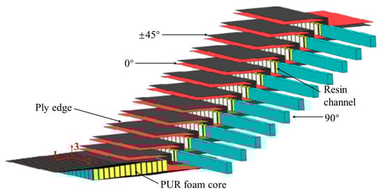
Figure 1.
Tiled sandwich (TS) panels using InfraCore® Inside technology.
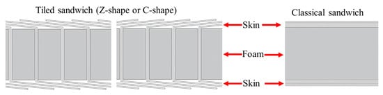
Figure 2.
Z- and C-shaped tiled sandwich panels vs. classical sandwich panel.
This internal transverse reinforcement structure endows TS panels with a significant crack-blocking capability (Figure 3). In traditional sandwich construction, accidental damage can trigger interfacial cracking between the skin and core owing to the absence of fibres in the direction of thickness, potentially resulting in catastrophic delamination. In contrast, the vertical reinforcement in a TS panel confines any crack to a single unit, effectively suppressing its propagation and substantially enhancing structural robustness []. Although TS panels have been field-proven in bridge applications, their mechanical behaviour is still only partially understood, and the publicly available literature contains mostly experimental investigations [,].
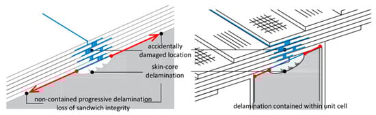
Figure 3.
Crack propagation resistance mechanisms in the classical sandwich panel vs. the tiled sandwich panel.
The exterior skins of TS panels are themselves an innovation called tiled laminates (TLs). In a TL, dry fabric layers are laid at a deliberate inclination and overlap like roof tiles, rather than in the conventional plane-parallel laminates (PP) (Figure 4). Manufacturing composite plates from tiled fabric strips enables the robotised production of highly complex composite structures in wrinkle-free and double-curved shapes. However, despite these advantages, systematic research on the structural response of both tiled sandwich panels and tiled laminates is virtually absent in the current scientific literature, aside from the limited experimental studies mentioned earlier [,].
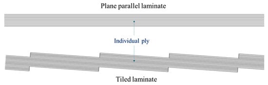
Figure 4.
Plane-parallel (PP) laminate vs. tiled laminate (TL).
Due to the inherent three-dimensional structure of TLs, the assumption of plane-parallelism on which classical laminate theory (CLT) is based [] becomes invalid, and purely analytical approaches cannot capture their mechanical response. Therefore, numerical simulation is of irreplaceable importance for accurately characterising the mechanical behaviour of TLs. However, to accurately describe the mechanical behaviour of TLs in numerical simulations, it is essential to employ a three-dimensional advanced damage model that comprehensively accounts for the damage evolution process of composite materials under three-dimensional stress conditions.
For conventional fibre-reinforced polymer (FRP) composites, numerous failure theories, such as the Tsai–Wu [], Hashin [], and the Puck criterion [], have been formulated. Building on these criteria, a variety of 2D and 3D progressive damage models (PDMs) have been implemented in commercial finite element software [,,]. Their applicability to TLs, however, remains limited. The 2D Hashin PDM in the ABAQUS material library [], for instance, omits out-of-plane stress and strain components and therefore delivers unsatisfactory results for three-dimensional loading conditions such as impact and drilling [,].
However, the existing 3D PDMs alleviate this shortcoming but still exhibit two deficiencies. Firstly, most 3D PDMs estimate the equivalent initial damage strain using the crude ratio of ultimate strength to Young’s modulus [,,], an approximation that lacks accuracy under multiaxial loading. Secondly, path-dependent effects arising from non-monotonic loading are seldom considered, and the failure to consider these leads to an overestimation of the ultimate load-carrying capacity []. To fill these gaps, the present authors recently proposed an enhanced 3D Hashin PDM [] that (a) calculates and records the equivalent initial damage strain during the numerical process, (b) considers all out-of-plane stress and strain components and damage in the thickness direction, and (c) captures the caused damage evolution under non-monotonic loading. The model has been systematically validated at both the finite-element level and the laminate scale and has demonstrated an excellent accuracy in predicting the tensile response of TLs.
Building further on this validated 3D PDM, the current study numerically investigates the influence of the inclination angle and overlap configuration on the elastic and damage behaviour of TLs subjected to three-point bending. The results further elucidate the underlying mechanics of TLs and provide meaningful guidance for their future design and application.
2. Three-Dimensional Progressive Damage Model (3D PDM)
In this study, the validated three-dimensional progressive damage model (3D PDM) described in [] based on the 3D Hashin damage criterion is employed to describe the initiation and damage evolution of a GFRP. At damage initiation, the 3D Hashin criterion distinguishes four failure modes: fibre tension (FT), fibre compression (FC), matrix tension (MT), and matrix compression (MC), which are expressed mathematically as Equations (1)–(4):
- (1)
- Fibre tension mode ()
- (2)
- Fibre compression mode ()
- (3)
- Matrix tension mode ()
- (4)
- Matrix compression mode ()
During the damage evolution stage, a fracture energy-based linear softening law is implemented. Specifically, the equivalent damage initiation strain () is determined, and the corresponding equivalent damage initiation stress () is recorded. The equivalent ultimate strain () is then calculated from the fracture energy. The governing relationships for the four damage modes are expressed as follows:
- (1)
- Fibre tension mode ()
- (2)
- Fibre compression mode ()
- (3)
- Matrix tension mode ()
- (4)
- Matrix compression mode ()
3. Numerical Modelling
3.1. Parameter Design
3.1.1. Overlap Configuration
In this study, overlap or non-overlap is defined as a key model variable because it controls the transition mechanism between adjacent stacks and thus the mechanical response. Overlap introduces a finite superposed length, creating a gradual thickness/stiffness gradient that redistributes the load and mitigates stress concentrations, while non-overlap forms an abrupt boundary that elevates local stresses and can trigger an earlier failure.
It is also industrially relevant: the overlap length is a practical layup parameter that manufacturers tune to balance performance (damage tolerance, fatigue life) against production costs and constraints (thickness, mass, process simplicity, quality control). Hence, modelling both overlap and non-overlap provides mechanism-level insight and decision support for design–manufacturing trade-offs in tiled laminates.
Therefore, two distinct overlap configurations are considered: non-overlap (Figure 5) and overlap (Figure 5). For clarity, the non-overlap configuration is designated as TLN (non-overlap TL), while the overlap configuration is denoted as TLO (overlap TL).
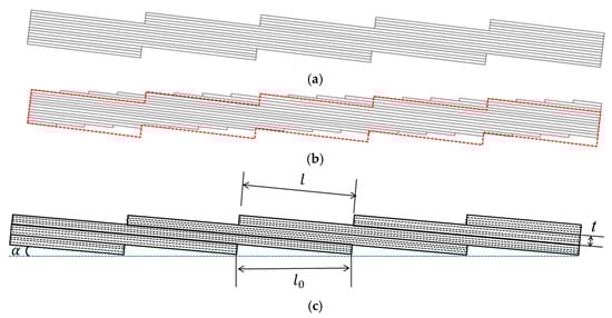
Figure 5.
(a) TLN (tiled laminate with non-overlap configuration); (b) TLO (tiled laminate with overlap configuration) with the same volume as the corresponding TLN; (c) calculation scheme of inclination angle for TLN and TLO. The red line indicates the outline of the TLN in the diagram.
3.1.2. Inclination Degree
The inclination angle, which is also fundamental to the design and manufacturing of TLs, has a significant impact on the mechanical behaviour of TLs.
As shown in Figure 5c, the inclination angle α is calculated as . Therefore, in order to investigate the influence of the inclination degree, the two sets of TLs are established with five inclination angles: 1°, 2°, 3°, 4°, and 5°. Additionally, a plane-parallel (PP) laminate model is included for the comparative analysis of mechanical performance.
Because the inclination angle limits the length of TL models, TLs with different inclination angles exhibit slightly different overall lengths (L) and spans (l). The width (w), thickness (h), length (L), and support span (l) for all TLs with different inclination angles are listed in Table 1. The ratio of h/L for every model greatly exceeds the ASTM D198 minimum requirement of 1/15. The three-point bending setup is illustrated in Figure 6. The two lower support noses are fixed, and a downward displacement is applied at midspan through the upper loading nose.

Table 1.
Actual geometric dimensions of TLs with different inclination angles.
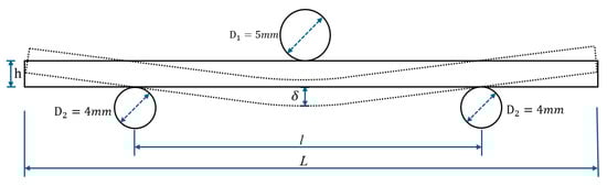
Figure 6.
Schematic diagram of the three-point bending simulation.
All numerical analyses use an eight-node linear brick element with reduced integration (C3D8R). A mesh sensitivity study identified an element size of 0.7 × 0.7 × 0.2 mm as the optimal compromise between computational efficiency and accuracy, as shown in Figure A1.
3.2. Material Properties
The material parameters selected in this paper are the same as those determined for GFRP (polyester resin and E-glass fibre) through a series of standardised tests in []. The mechanical properties of the plies are shown in Table 2.
Table 2.
Material properties for E-glass/polyester [].
3.3. Interlaminar Properties
To characterise interlaminar damage, this paper introduces a cohesive zone model (CZM) integrated with the general contact algorithm in the ABAQUS framework to simulate inter-layer delamination phenomena.
The model utilises surface-based cohesive interactions to describe the interfacial adhesive contact stress behaviour through a bilinear traction–separation relationship [,]. The quadratic traction damage initiation criterion (Equation (9)) is adopted to predict the onset of interlaminar damage. In the equation, , , and represent the contact stresses in the normal and two shear directions, respectively, while , , and are the critical contact stresses in the respective modes. The propagation of delamination is characterised using the B-K criterion [], which is based on the mixed-mode energy release rate, with the relevant material coefficient η in the B-K formula set to 2 in this study.
The interlaminar bonding properties obtained from the experiments are presented in Table 3.
Table 3.
Interlaminar properties.
4. Results and Discussion
The load–deflection relationships of two sets of TLs with different inclination angles under three-point bending, obtained through numerical simulations, are shown in Figure 7, which also includes a plane-parallel (PP-0°) configuration as a reference to show the geometric effects. Based on the results, the mechanical behaviour of the elastic stage and non-linear stage is discussed.
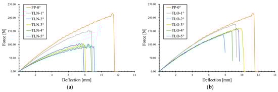
Figure 7.
Load–deflection relationships of (a) TLNs and (b) TLOs.
4.1. Bending Behaviour of TL in Elastic Stage
4.1.1. Elastic Bending Stiffness
Due to the periodic variation in the cross-sectional geometry and stacking sequence of the ply along the longitudinal axis of the TL along the longitudinal direction, only the overall bending stiffness EI of the TL can be calculated using Equation (10).
Figure 8 illustrates the relationship between the bending stiffness (EI) and inclination angle in the two sets of TL models, as derived from the load–deflection curves. It can be observed that the overlapped configuration (TLO) consistently exhibits a superior bending stiffness compared to the non-overlapped configuration (TLN) at identical inclination angles, indicating that the overlap geometry more effectively leverages the bending performance potential of tiled laminates.
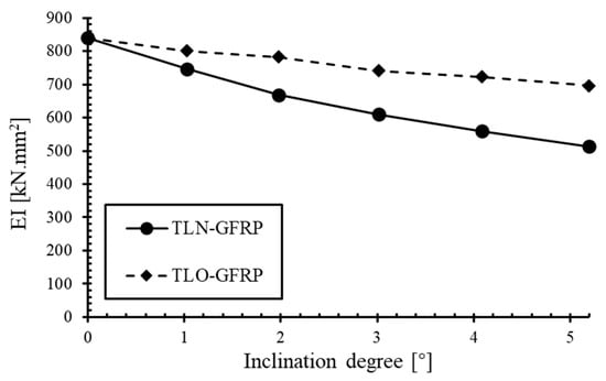
Figure 8.
Relationship between bending stiffness (EI) and inclination angle of TLN-GFRP and TLO-GFRP.
Both sets of TLN and TLO demonstrate a monotonic reduction in bending stiffness with increasing inclination angles. For the TLN, as the inclination angle increases from 1° to 5°, the bending stiffness decreases from 740 kN·mm2 to 510 N·mm2, representing a total reduction of approximately 31% (averaging approximately 6.9% per degree). In contrast, the set of TLOs exhibits a more modest decline from 800 kN·mm2 to 700 kN·mm2 over the same inclination angle range, corresponding to a total reduction of only 12.5% (averaging approximately 2.5% per degree). It is evident that the non-overlap configuration demonstrates a significantly greater sensitivity to the inclination angle, whereas the overlap configuration exhibits a significant advantage in terms of bending stiffness retention.
However, the differences in the bending stiffness between these two model sets stems not only from geometric differences but also from the resulting changes in laminate stacking sequences. Excluding the reduced sections, TLNs maintain a uniform stacking sequence of [90/45/0/-45/90]3s throughout all cross-sections. Conversely, for TLOs, except for the reduced section, there are five possible stacking sequences for the sections: namely [90/45/0/-45/90]3s, [45/0/-45/90/90]3s, [0/-45/90/90/45]3s, [45/90/90/45/0]3s, and [90/90/45/0/-45]3s. For the layup [90/45/0/-45/90]3s, the sequence constitutes a balanced antisymmetric laminate which, according to CLT and its associated ABD matrix, exhibits extension–bending coupling but no bending–twisting coupling. However, the other four stacking sequences simultaneously exhibit extension–bending and bending–twisting couplings, further contributing to the distinctive mechanical behaviour observed in TLOs.
To isolate the influence of the geometric configuration from material effects on the bending performance of TLs, the material parameters of the above two sets of TLs are re-placed with isotropic steel, denoted as TLN-steel and TLO-steel, respectively. The Young’s modulus and Poisson’s ratio of steel are 210 GPa and 0.3, respectively. Figure 9 presents the relationship between the bending stiffness and inclination angle obtained from three-point bending simulations of steel TL models.
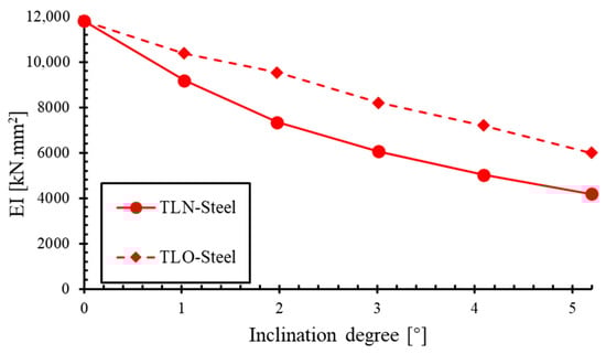
Figure 9.
Relationship between bending stiffness (EI) and inclination angle of TLN-steel and TLO-steel.
The trend of the relationship between the bending stiffness and inclination angle observed in the steel models is consistent with the trend observed when GFRP is used. The overlap models (TLO-steel) consistently demonstrate higher bending stiffnesses compared to their non-overlap counterparts (TLN-steel) at identical inclination angles, while both simultaneously exhibiting a decreasing stiffness with an increasing inclination angle. This consistency across different material systems confirms that the superior bending performance of the overlap configuration is predominantly attributable to its geometric characteristics rather than material anisotropy effects. Hence, the TL with an overlapping geometric configuration inherently has a better bending performance than the one with non-overlapping arrangements.
Figure 10 presents the relationship between the normalised bending stiffness and inclination angles across all four sets of TL models (TLN-GFRP, TLO-GFRP, TLN-Steel, TLO-Steel), in which the bending stiffness values have been normalised against their respective plane-parallel (PP) laminate counterparts, thereby eliminating different material property effects and isolating the influence of the geometric configuration (TLN/TLO) and inclination angle (1° to 5°) on flexural performance.

Figure 10.
Relationship between normalised bending stiffness and inclination angle of TLN-GFRP, TLO-GFRP, TLN-steel, and TLO-steel.
It can be observed that, at any inclination angle, the normalised GFRP curves (black line) consistently lie above the steel curve (red line), maintaining a stiffness advantage of 5–35%. Furthermore, the stiffness advantage of the GFRP material in TLOs becomes more pronounced than in TLNs as the inclination angle increases. This indicates that the additional bending–torsion coupling in TLO-GFRP contributes supplementary bending stiffness to the tiled laminate structure.
To further investigate how extension coupling affects the variation in the normalised bending stiffness with inclination angle in TLs, TLNs with a uniform [0/0/0/0/0] ply sequence are simulated at inclination angles of 1°, 2°, 3°, 4°, and 5° under three-point bending. Figure 11 presents the resulting elastic-stage normalised bending stiffness versus the inclination angle. TLN1°-[0/0/0/0/0] exhibits a higher normalised bending stiffness than the [90/-45/0/45/90] counterpart. However, as the angle increases, its stiffness falls below that of the [90/-45/0/45/90] stacking. These findings demonstrate that, the weaker the TL (including more 90° plies), the more the impact of the “tiled” configuration on the TL’s bending performance is for higher inclination degrees. However, for angles of 1 to 3°, the ply configuration has a relatively small influence.
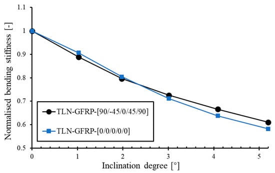
Figure 11.
Relationship between normalised bending stiffness and inclination angle of TLN-GFRP with stacking sequence [90/-45/0/45/90] and [0/0/0/0/0].
4.1.2. Moment of Inertia Variations Across Different TL Geometric Configurations
Having investigated the relationship between the bending stiffness and both the overlap configuration and inclination angle, it becomes essential to examine how the equivalent moment of inertia () changes with variations in the overlap configuration and inclination angle.
To eliminate material influences on the relationship between the geometric configuration and moment of inertia, the analysis is again conducted on the two sets of steel TLs (TLO-steel and TLN-steel). To further determine the tensile modulus (E), a tensile load is applied on the TLN-steel and TLO-steel. For both TLO and TLN configurations, the tensile modulus (E) is defined as the tensile stress in the loading direction divided by the corresponding tensile strain, with the resulting tensile modulus illustrated in Figure 12. The equivalent moment of inertia () for each configuration is then obtained by dividing the bending stiffness (EI) from three-point bending simulations by the tensile modulus (E); the relationship between the equivalent moment of inertia () and inclination degree is shown in Figure 13.
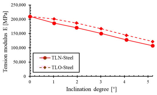
Figure 12.
Relationship between tension modulus (E) and inclination degree of TLN-steel and TLO-steel.
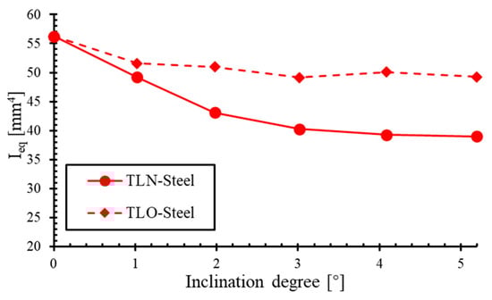
Figure 13.
Relationship between equivalent moment of inertia () and inclination degree of TLN-steel and TLO-steel.
An observation of the results reveals that, for the TLN-steel, the moment of inertia decreases significantly with an increasing inclination angle, with a change range of 20% (38.9 to 48.9 mm4). In contrast, the overlap configuration (TLO-steel) maintains a relatively constant inertia, with a change range of 0.5% (49.1 to 51.6 mm4), exhibiting a considerably more gradual curve. The separation between these two curves progressively widens as the inclination angle increases.
These findings demonstrate that the equivalent moment of inertia () in the overlap configuration exhibits minimal sensitivity to the inclination angle, resulting in a more stable bending performance. Conversely, for the TLN configuration, diminishes significantly with an increasing inclination angle when below 3°, whereas, beyond this threshold, becomes substantially less sensitive to further angular changes.
4.1.3. Stress Distribution in the Elastic Stage
Because the stress distribution in tiled laminates under bending is complex and our primary concern is the local high-stress levels caused by the reduced sections, we focus on how the peak stress varies with inclination angle, geometric configuration, and material. To remove the effects caused by slight differences in span length, 10 models with an identical span, namely PP-Steel, TLN1°-Steel, TLO1°-Steel, TLN4°-Steel, TLO4°-Steel, PP-GFRP, TLN1°-GFRP, TLO1°-GFRP, TLN4°-GFRP, and TLO4°-GFRP, are selected to compare their elastic-stage stress distributions under three-point bending. To ensure a better contact between the loading and supporting noses and the TLs and to maintain stable loading, the loading and support noses are positioned not at the reduced sections but midway between two adjacent reduced sections.
Under identical levels of the applied load, the effects of different inclination angles and the presence or absence of an overlap–lap configuration on the elastic response under bending are compared for two materials (steel and GFRP). Because the elastic moduli of steel and GFRP differ substantially (by about an order of magnitude), different midspan loads are used in the respective comparisons. For the isotropic material (steel), when the effects of the inclination angle and overlap configuration on the elastic response under bending are compared, the midspan load is set to 100 N. For GFRP, in the corresponding comparison, the midspan load is set to 11.5 N. This selection is considered reasonable because the comparisons are performed within each material individually, thereby allowing the influence of each key parameter on the elastic bending behaviour for that material to be investigated.
Under an identical applied load (midspan reaction ≈ 100 N), the stress distributions for PP-Steel and the four TL-Steel models are shown in Figure 14. First, regardless of geometric configuration or inclination angle, every TL variant exhibits a clear neutral axis. At this load level, PP-Steel (Figure 14a) has the lowest peak stress, with a maximum of only 75.1 MPa appearing at the top and bottom of the midspan section.
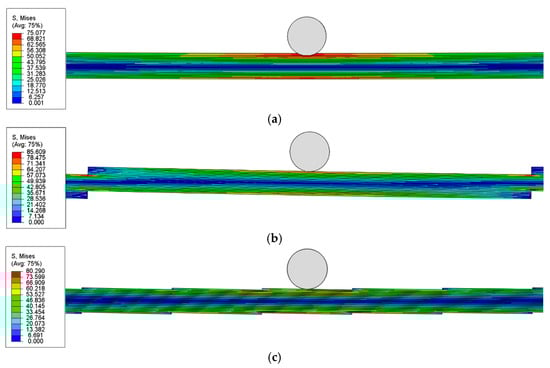
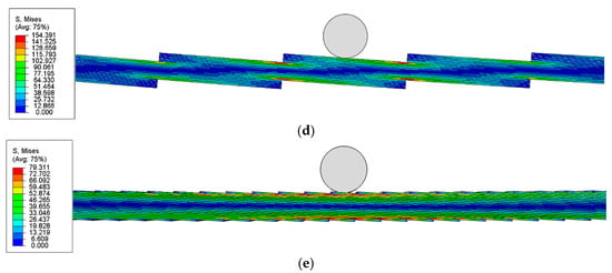
Figure 14.
Stress distribution of PP-Steel and TLs-Steel under the same applied load: (a) PP-Steel, (b) TLN1°-Steel, (c) TLO1°-Steel, (d) TLN4°-Steel, (e) TLO4°-Steel.
In contrast, all four TL-Steel models show higher peak stresses, which are caused by stress concentrations at their reduced sections and occurring at the reduced sections just beside the midspan. More specifically, under the same loading, TLN4°-Steel (Figure 14d) reaches a maximum stress of 154.4 MPa, far exceeding the 85.6 MPa of TLN1°-Steel (Figure 14e). Meanwhile, as shown in Figure 14b,c, TLO4°-Steel and TLO1°-Steel both peak at about 80 MPa. This result indicates that, apart from material differences, the overlapping TL geometry (TLO) is far less sensitive to changes in the inclination angle than the non-overlapped TL (TLN).
Under an identical applied load, with the midspan reaction force at approximately 11.5 N, the stress distributions along one axis for PP-GFRP and the various TL-GFRP models are shown in Figure 15. PP-GFRP exhibits a maximum stress of 10.2 MPa, which is lower than that of all four TL-GFRP specimens and consistent with the steel-based results discussed earlier. However, unlike the steel case, the peak stress in PP-GFRP does not occur at the top or bottom of the midspan section but as expected within the 0° plies, indicating that material properties also influence the stress distribution.
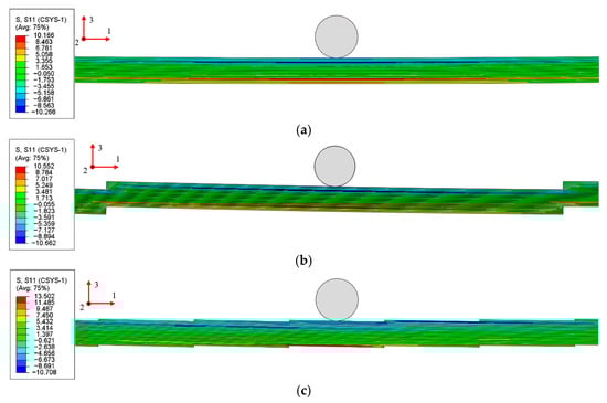
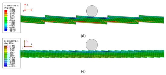
Figure 15.
Stress distribution of PP-GFRP and TLs-GFRP under the same applied load: (a) PP-GFRP, (b) TLN1°-GFRP, (c) TLO1°-GFRP, (d) TLN4°-GFRP, (e) TLO4°-GFRP.
Likewise, in the TLN 1°-GFRP model, the maximum stress is found not at the reduced sections but in the 0° plies at midspan (.). In contrast, in the TLO 1°-GFRP, TLN 4°-GFRP, and TLO 4°-GFRP specimens, the highest stresses occur at the reduced sections rather than at midspan. Moreover, the two overlapping configurations (TLO 1°-GFRP and TLO 4°-GFRP) display almost identical peak stresses of about 13.5 MPa, whereas the non-overlapped configurations (TLN 1°-GFRP and TLN 4°-GFRP) exhibit a larger spread, with maximum stresses of 10.6 MPa and 12.9 MPa, respectively, which amount to about an 18% difference.
4.2. Bending Behaviour of TL in the Non-Linear Stage
4.2.1. Ultimate Midspan Bending Moment
Due to slight variations in span lengths across TL specimens with different inclination angles, the ultimate midspan bending moment (Mmax = 0.25 × P × l) is employed to evaluate the ultimate flexural strength of TLs with varying inclination angles. Figure 16 illustrates the influence of the inclination angle on the ultimate midspan bending moment of TLs under three-point bending, with a particular emphasis on comparing the performance between TLNs and TLOs. The results demonstrate that both stacking configurations exhibit a pronounced decreasing trend in the ultimate midspan moment Mmax as the inclination angle increases from 1° to 5°.
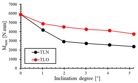
Figure 16.
The relationship between ultimate midspan bending moment (Mmax) and inclination degree.
When the inclination angle is 0° (PP laminate), the ultimate midspan bending moment reaches approximately 5895.46 N·mm, significantly exceeding the moment capacity of both TLN and TLO. This indicates the superior moment-bearing capacity of the PP laminate compared to TL. Additionally, at any given inclination angle, the set of TLOs consistently demonstrates a higher ultimate midspan bending moment than its TLN counterparts.
As the inclination angle increases from 1° to 2°, the ultimate midspan bending moment of TLN decreases from 4191.07 N·mm to 2937.06 N·mm, representing a substantial reduction of approximately 30.0%. In contrast, the TLO configuration exhibits a more modest decrease from 4885.19 N·mm to 4538.36 N·mm, corresponding to only a 7.1% reduction. This indicates that the moment-bearing capacity of TLNs is significantly more sensitive to inclination angle variations at lower angular ranges.
When the inclination angle exceeds 2°, the rate of decrease in the ultimate midspan bending moment moderates for the TLN configuration, while the TLO configuration maintains a relatively consistent rate of decline. This indicates that the sensitivity of the TLN’s ultimate moment to the inclination angle diminishes as the inclination angle increases.
At an inclination angle of 5°, the ultimate midspan bending moment of TLN5° decreases to approximately 2385.25 N·mm, representing a 43.1% reduction compared to TLN1° (4191.07 N·mm), whereas the corresponding reduction for the TLO configuration is 23.1%. This result indicates not only the superior moment capacity of the TLO configuration, but also more stable values of the midspan peak bending moment with increasing inclination angles.
In summary, this investigation demonstrates that inclination angle has a significant impact on the ultimate midspan bending moment of both TLN and TLO configurations, with the TLO geometry exhibiting more stable values of the midspan maximum bending moment.
4.2.2. Failure Modes
As analysed in Section 4.1.3 for stress distribution during the elastic stage, the TLO and TLN configurations, due to the stress concentration effects caused by their overlap, result in reduced sections on both sides of the midspan section being subjected to higher stress levels, thereby making this section the most vulnerable to failure. This suggests that these sections would serve as critical failure initiation regions. Figure 17, Figure 18, Figure 19, Figure 20 and Figure 21 show the matrix tension damage (SDV3) and matrix compression damage (SDV4) immediately before and after ultimate failure. It can be observed that all the TLs demonstrate failure initiation at the reduced sections near the loading nose. However, different geometric configurations and inclination angles significantly influence the damage initiation and progression patterns.
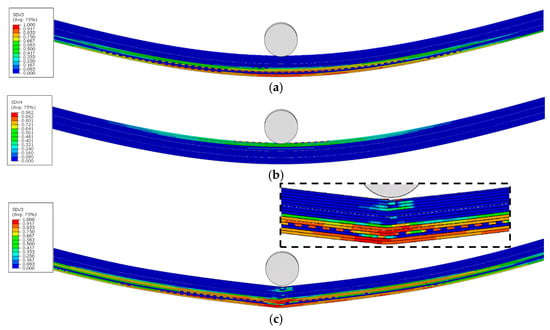
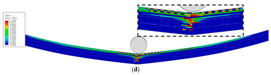
Figure 17.
Damage variable distribution of PP-GFRP before and after final failure: (a) MT damage before ultimate failure, (b) MC damage before ultimate failure, (c) MT damage after ultimate failure, (d) MC damage after ultimate failure.
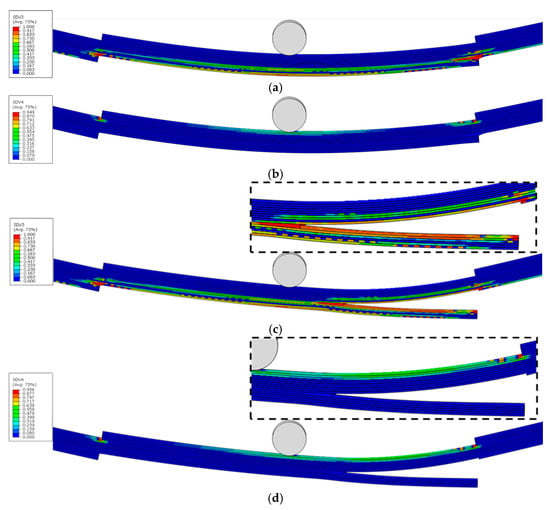
Figure 18.
Damage variable distribution of TLN1°-GFRP before and after final failure: (a) MT damage before ultimate failure, (b) MC damage before ultimate failure, (c) MT damage after ultimate failure, (d) MC damage after ultimate failure.
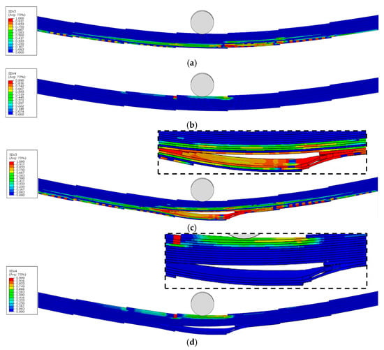
Figure 19.
Damage variable distribution of TLO1°-GFRP before and after final failure: (a) MT damage before ultimate failure, (b) MC damage before ultimate failure, (c) MT damage after ultimate failure, (d) MC damage after ultimate failure.
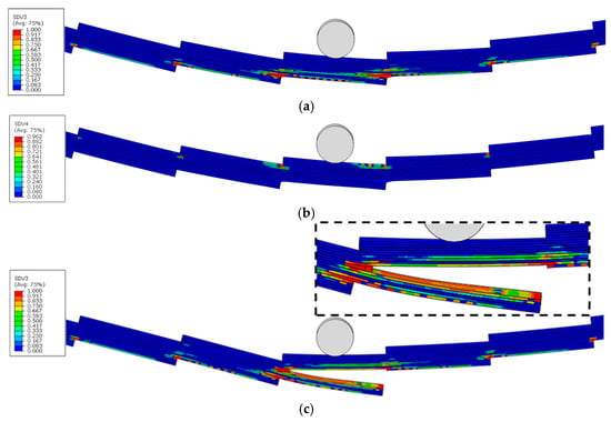
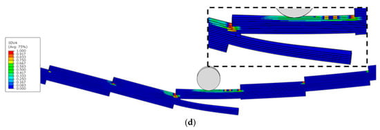
Figure 20.
Damage variable distribution of TLN4°-GFRP before and after final failure: (a) MT damage before ultimate failure, (b) MC damage before ultimate failure, (c) MT damage after ultimate failure, (d) MC damage after ultimate failure.
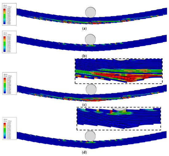
Figure 21.
Damage variable distribution of TLO4°-GFRP before and after final failure: (a) MT damage before ultimate failure, (b) MC damage before ultimate failure, (c) MT damage after ultimate failure, (d) MC damage after ultimate failure.
Under the same inclination angles, TLOs exhibit a more uniform damage distribution compared to corresponding TLNs, where damage remains predominantly localised around the reduced sections. When maintaining the same geometric configuration, TLs with larger inclination angles display a more homogeneous damage distribution. This can be attributed to the increased number of reduced sections present in higher inclination angle configurations, facilitating a more uniform damage distribution throughout the model.
Figure 17, Figure 18, Figure 19, Figure 20 and Figure 21c,d show the ultimate failure modes of PP, TLN-1°, TLO-1°, TLN-4°, and TLO-4° specimens. Consistent with stress distributions in the elastic stage, where upper cross-sectional regions are under compressive stress states and lower regions undergo tensile stress states, all configurations (PP, TLN, and TLO) exhibit matrix compression damage in the upper sections and matrix tensile damage in the lower sections at ultimate failure.
However, an examination of the three geometric configurations reveals fundamentally different ultimate failure mechanisms between PP and TL. For the PP configuration, ultimate failure results from the combined contribution of matrix compressive damage in the upper region and matrix tensile damage in the lower region of the midspan section. In contrast, both TLNs and TLOs at ultimate failure show no significant matrix compression damage in their upper regions. Instead, their ultimate failures are predominantly governed by the matrix tensile damage occurring in the 90° plies of the lower regions of reduced sections. A comparative analysis further reveals that TLN exhibits a more sudden failure, with a crack rapidly propagating and disrupting the structural integrity of the specimen, completely losing its flexural load-bearing capacity. Conversely, TLO demonstrates a more progressive failure, with a crack initiating within the interior of the specimen, enabling TLO to maintain a partial flexural load-bearing capacity even after damage initiation.
Therefore, it can be concluded that the failure of PPs under three-point bending results from the combined effect of tensile damage in lower regions and compressive damage in upper regions, while TL failure is entirely controlled by tensile damage in lower regions. All TL failures originate at the reduced sections. Compared to TLN, the superior geometric configuration of TLO provides a higher bending load bearing capacity.
It should be noted that, although cohesive surfaces are introduced at the interfaces to represent interlaminar damage in the model, the cohesive damage is not activated at final failure. Since the 3D PDM accounts for out-of-plane stiffness degradation, the interlaminar damage is represented via material element deletion.
5. Conclusions
This study employs an enhanced three-dimensional progressive damage model (3D PDM) based on the Hashin failure criterion to systematically investigate the influence of overlap configuration and inclination angle on the bending performance of tiled laminates (TLs) through the numerical simulation of three-point bending (3PB) tests. The key findings are as follows:
- Elastic-stage performance and stiffness mechanisms
In the elastic stage, the bending stiffness decreases with increasing inclination angles for both configurations. However, the overlapped configuration (TLO) demonstrates a significantly lower sensitivity to inclination angle variations compared to the non-overlapped configuration (TLN). Furthermore, unlike TLN, the TLO configuration exhibits periodically varying layup sequences along the longitudinal direction, generating an additional bending stiffness through bending–twisting coupling effects under three-point bending loads. To eliminate the influence of material properties, a fibre-reinforced polymer (FRP) is substituted with steel in comparative analyses, confirming that, even with identical isotropic material properties, the TLO configuration still demonstrates a superior flexural performance compared to TLN. A quantitative analysis of equivalent moments of inertia across different configurations and inclination angles reveals that TLO maintains a relatively stable equivalent moment of inertia (), while TLN shows significant sensitivity to inclination angle variations.
- Non-linear behaviour and failure mechanisms
In the non-linear stage, material failure consistently initiates at the reduced sections in both TLOs and TLNs. Compared with a plane-parallel (PP) laminate of identical stacking sequence, TLs similarly exhibit matrix compression damage in the upper compression zone and matrix tensile damage in the lower tension zone. However, while the final failure mode of the PP laminate is governed by compression failure in the upper region and tensile failure in the lower region, the ultimate failure in both TL configurations is primarily dominated by matrix tensile failure at the bottom region. Although damage in both TLOs and TLNs initiates as matrix tensile failure within the reduced sections, the ultimate failure modes differ substantially. For TLNs, once a crack forms, it propagates rapidly, leading to a delamination that severely compromises the structural integrity and results in a rapid loss of load-carrying capacity. In contrast, in TLOs, crack propagation is comparatively slow, and the damage remains confined within the TLO, which preserves a degree of structural integrity and prevents an immediate loss of load capacity, as demonstrated by the damage evolution and load–deflection responses.
- Design implications
In the design of TLs, particular attention should be paid to the reduced sections, as they constitute the most probable site for damage initiation under bending. The use of an overlapping configuration can effectively improve the bending load capacity of TLs, increase structural ductility, and effectively control crack propagation compared to non-overlapped configurations. Therefore, for TL designs with different geometric parameters, the TLO is expected to maintain a lower sensitivity to design variations and superior damage tolerance compared to TLN.
Author Contributions
Conceptualization, Y.Z., W.D.C. and W.V.P.; methodology, Y.Z.; software, Y.Z.; validation, Y.Z., W.D.C. and W.V.P.; formal analysis, Y.Z.; investigation, Y.Z.; data curation, Y.Z.; writing—original draft preparation, Y.Z.; writing—review and editing, Y.Z., W.D.C. and W.V.P.; supervision, W.D.C. and W.V.P.; project administration, W.D.C. All authors have read and agreed to the published version of the manuscript.
Funding
This research was funded by China Scholarship Council (CSC Grant No. 202106090037).
Data Availability Statement
The data that support the findings of this study are not publicly available due to privacy and confidentiality agreements. Data are available from the corresponding author upon reasonable request.
Acknowledgments
The authors gratefully acknowledge the financial support from the China Scholarship Council.
Conflicts of Interest
The authors declare no conflicts of interest.
Appendix A
This study conducts mesh sensitivity analyses for the TLN-2° and TLO-2° under three-point bending using Abaqus/Explicit (element C3D8R). With the element thickness fixed (t = 0.2 mm), we systematically examine the scaling of computational time and the effect of in-plane element size on the midspan ultimate bending moment.

Figure A1.
Mesh sensitive analyses of TLN-2° and TLO-2°: (a) Element size vs. midspan ultimate bending moment, (b) Element size vs. computational time.
References
- Jarrett, W.; Jeffs, S.P.; Korkees, F.; Rawson, M. The Opportunities and Challenges of Hybrid Composite Driveshafts and Their Couplings in the Aerospace Industry: A Review. Compos. Struct. 2023, 320, 117203. [Google Scholar] [CrossRef]
- Monaldo, E.; Nerilli, F.; Vairo, G. Basalt-Based Fiber-Reinforced Materials and Structural Applications in Civil Engineering. Compos. Struct. 2019, 214, 246–263. [Google Scholar] [CrossRef]
- Sreejith, M.; Rajeev, R.S. Fiber Reinforced Composites for Aerospace and Sports Applications. In Fiber Reinforced Composites; Elsevier: Amsterdam, The Netherlands, 2021; pp. 821–859. ISBN 978-0-12-821090-1. [Google Scholar]
- Al-Furjan, M.S.H.; Shan, L.; Shen, X.; Zarei, M.S.; Hajmohammad, M.H.; Kolahchi, R. A Review on Fabrication Techniques and Tensile Properties of Glass, Carbon, and Kevlar Fiber Reinforced Rolymer Composites. J. Mater. Res. Technol. 2022, 19, 2930–2959. [Google Scholar] [CrossRef]
- Topol, H.; Al-Chlaihawi, M.J.; Demirkoparan, H.; Merodio, J. Bifurcation of Fiber-Reinforced Cylindrical Membranes under Extension, Inflation, and Swelling. J. Appl. Comput. Mech. 2023, 9, 113–128. [Google Scholar] [CrossRef]
- Mara, V.; Haghani, R.; Harryson, P. Bridge Decks of Fibre Reinforced Polymer (FRP): A Sustainable Solution. Constr. Build. Mater. 2014, 50, 190–199. [Google Scholar] [CrossRef]
- Sonnenschein, R.; Gajdosova, K.; Holly, I. FRP Composites and Their Using in the Construction of Bridges. Procedia Eng. 2016, 161, 477–482. [Google Scholar] [CrossRef]
- Zhou, X.-Y.; Wang, N.-W.; Xiong, W.; Wu, W.-Q.; Cai, C.S. Multi-Scale Reliability Analysis of FRP Truss Bridges with Hybrid Random and Interval Uncertainties. Compos. Struct. 2022, 297, 115928. [Google Scholar] [CrossRef]
- FiberCore Europe. InfraCore Technology. Available online: https://www.fibercore-europe.com/en/composite-as-a-structural-material/infracore-technology/ (accessed on 29 September 2025).
- Hiddingh, J.; Grefhorst, R.; Veltkamp, M. Full-Scale Fatigue Testing with Initial Damage as Validation of FRP Road Bridge Design; IABSE: Stockholm, Sweden, 2016; pp. 1280–1287. [Google Scholar]
- Vaerwyckweg, V. Structural Behaviour and Robustness Assessment of an Infracore® Inside Bridge Deck Specimen Subjected to Static and Dynamic Local Loading. In Proceedings of the 21st International Conference on Composite Materials, Xi’an, China, 20–25 August 2017. [Google Scholar]
- Smits, J. Fiber-Reinforced Polymer Bridge Design in the Netherlands: Architectural Challenges toward Innovative, Sustainable, and Durable Bridges. Engineering 2016, 2, 518–527. [Google Scholar] [CrossRef]
- Uyttersprot, J.; De Corte, W.; Van Paepegem, W. Mechanical Characterization of GFRP Tiled Laminates for Structural Engineering Applications: Stiffness, Strength and Failure Mechanisms. J. Compos. Sci. 2024, 8, 265. [Google Scholar] [CrossRef]
- Uyttersprot, J.; De Corte, W.; Van Paepegem, W. High-Cycle Fatigue Behaviour and Structural Robustness of Glass Fibre-Reinforced Polymer Tiled Web-Core Sandwich Panel Unit Cells in Load-Bearing Structures. J. Compos. Sci. 2024, 8, 538. [Google Scholar] [CrossRef]
- Saeed, K.; McIlhagger, A.; Harkin-Jones, E.; Kelly, J.; Archer, E. Predication of the In-Plane Mechanical Properties of Continuous Carbon Fibre Reinforced 3D Printed Polymer Composites Using Classical Laminated-Plate Theory. Compos. Struct. 2021, 259, 113226. [Google Scholar] [CrossRef]
- Li, J.; Yang, J.; Liu, Q.; Xu, J.; Zhang, W.; Yang, Q. An Elastoplastic Damage Ice Material Model Based on Modified Tsai-Wu Yield Criterion: Experiment, Theory and Numerical Application. Constr. Build. Mater. 2024, 438, 137149. [Google Scholar] [CrossRef]
- Hashin, Z. Failure Criteria for Unidirectional Fiber Composites. J. Appl. Mech. 1980, 47, 329–334. [Google Scholar] [CrossRef]
- Puck, A.; Schürmann, H. Failure Analysis of FRP Laminates by Means of Physically Based Phenomenological Models. Compos. Sci. Technol. 2002, 62, 1633–1662. [Google Scholar] [CrossRef]
- Azhdari, S.; Taheri-Behrooz, F. An Experimental and Numerical Investigation on Bending after Impact Strength of Glass Laminate Aluminium Reinforced Epoxy. Compos. Part A Appl. Sci. Manuf. 2023, 171, 107578. [Google Scholar] [CrossRef]
- Zhu, P.; Li, G.; Jia, Q.; Zhang, Y.; Wang, Y.; Zhou, L. An Efficient Multi-Scale Method for Failure Mechanism Analysis of SiCf/Ti Composites with Experimental Validation. Mater. Charact. 2024, 216, 114233. [Google Scholar] [CrossRef]
- Ait Mohammed, M.; Tarfaoui, M. A Progressive Damage Modelling of Glass/Epoxy Cylindrical Structure Subjected to Low-Velocity Impact. Eng. Fail. Anal. 2022, 134, 106036. [Google Scholar] [CrossRef]
- Fakoor, M.; Mohammad Navid Ghoreishi, S. Experimental and Numerical Investigation of Progressive Damage in Composite Laminates Based on Continuum Damage Mechanics. Polym. Test. 2018, 70, 533–543. [Google Scholar] [CrossRef]
- Li, X.; Ma, D.; Liu, H.; Tan, W.; Gong, X.; Zhang, C.; Li, Y. Assessment of Failure Criteria and Damage Evolution Methods for Composite Laminates under Low-Velocity Impact. Compos. Struct. 2019, 207, 727–739. [Google Scholar] [CrossRef]
- Liao, B.B.; Liu, P.F. Finite Element Analysis of Dynamic Progressive Failure of Plastic Composite Laminates under Low Velocity Impact. Compos. Struct. 2017, 159, 567–578. [Google Scholar] [CrossRef]
- Liu, Y.; Hou, Y.; Sapanathan, T.; Meng, L.; Xu, Y. Multiscale Modeling of the Mechanical Behavior of 3D Braided CFRP Composites under Uniaxial Tension. Compos. Struct. 2023, 306, 116601. [Google Scholar] [CrossRef]
- Zhang, D.; Zhou, J.; Wang, J.; Zhang, W.; Guan, Z. A Comparative Study on Failure Mechanisms of Open-Hole and Filled-Hole Composite Laminates: Experiment and Numerical Simulation. Thin-Walled Struct. 2024, 198, 111730. [Google Scholar] [CrossRef]
- Zhang, Y.; Van Paepegem, W.; De Corte, W. An Enhanced Progressive Damage Model for Laminated Fiber-Reinforced Composites Using the 3D Hashin Failure Criterion: A Multi-Level Analysis and Validation. Materials 2024, 17, 5176. [Google Scholar] [CrossRef]
- Kuhn, C.; Müller, R. A Continuum Phase Field Model for Fracture. Eng. Fract. Mech. 2010, 77, 3625–3634. [Google Scholar] [CrossRef]
- De Maio, U.; Greco, F.; Lonetti, P.; Pranno, A. A Combined ALE-Cohesive Fracture Approach for the Arbitrary Crack Growth Analysis. Eng. Fract. Mech. 2024, 301, 109996. [Google Scholar] [CrossRef]
- Benzeggagh, M.L.; Kenane, M. Measurement of Mixed-Mode Delamination Fracture Toughness of Unidirectional Glass/Epoxy Composites with Mixed-Mode Bending Apparatus. Compos. Sci. Technol. 1996, 56, 439–449. [Google Scholar] [CrossRef]
Disclaimer/Publisher’s Note: The statements, opinions and data contained in all publications are solely those of the individual author(s) and contributor(s) and not of MDPI and/or the editor(s). MDPI and/or the editor(s) disclaim responsibility for any injury to people or property resulting from any ideas, methods, instructions or products referred to in the content. |
© 2025 by the authors. Licensee MDPI, Basel, Switzerland. This article is an open access article distributed under the terms and conditions of the Creative Commons Attribution (CC BY) license (https://creativecommons.org/licenses/by/4.0/).