Abstract
In recent years, finite element analysis (FEA) models of different porous scaffold shapes consisting of various materials have been developed to predict the mechanical behaviour of the scaffolds and to address the initial goals of 3D printing. Although mechanical properties of polymeric porous scaffolds are determined through FEA, studies on the polymer nanocomposite porous scaffolds are limited. In this paper, FEA with the integration of material designer and representative volume elements (RVE) was carried out on a 3D scaffold model to determine the mechanical properties of boron nitride nanotubes (BNNTs)-reinforced gelatin (G) and alginate (A) hydrogel. The maximum stress regions were predicted by FEA stress distribution. Furthermore, the analysed material model and the boundary conditions showed minor deviation (4%) compared to experimental results. It was noted that the stress regions are detected at the zone close to the pore areas. These results indicated that the model used in this work could be beneficial in FEA studies on 3D-printed porous structures for tissue engineering applications.
1. Introduction
In recent years, 3D bioprinting has significantly boosted the research and development in tissue regeneration [1]. The technique can be used to create complex tissue structures according to patient-specific geometries and compositions. Compared to 3D bioprinting, traditional methods are restricted in producing scaffolds with an adequate pore size that enhances in vitro behaviour. For instance, the internal geometry of the scaffold greatly influences cell adhesion, proliferation, and nutrient transportation for tissue regeneration. Customising suitable scaffold geometry for creating biological environments is addressed by 3D-printing technology rather than traditional methods [1,2,3,4]. Scaffolds generated by 3D printing have lattice structures with various pore sizes and serve as a template for cell interaction and cell-extracellular matrix formation. These scaffolds are required to furnish structural assistance for the newly generated tissue. In addition to delivering the required biological properties, the scaffolds provide biomechanical properties during tissue regeneration and implantation [5]. Biomechanical properties, such as shear stress, deformation, and tensile or compressive stress, must match with natural healthy tissue or bone structure properties. Ideal scaffolds are produced with a well-regulated pore structure and can reproduce the shape of the implants [6,7,8,9]. Research studies have indicated that anisotropic porous structures with a combination of small and large pores in various shapes are advantageous for cell growth and can improve cell proliferation over time [7,10,11]. Therefore, characterising and predicting the biomechanical properties of 3D-printed scaffolds using different materials is essential. Identifying suitable biomaterials that support biomechanical and biological properties is a significant challenge in 3D bioprinting for tissue-engineering applications. Natural and synthetic polymers are widely used to produce scaffolds through 3D bioprinting [12,13,14,15,16]. By contrast, natural or synthetic polymers are limited in terms of their biomechanical properties. Thus, researchers have been focusing on hybrid polymer or polymer nanocomposite-based materials applicable in 3D bioprinting techniques for tissue engineering. However, most studies on these materials are conducted through experiments, which is time consuming and costly. Therefore, finite element modelling (FEM) and FEA provide the alternatives for determining the biomechanical properties of biomaterials without printing or performing extensive, time-consuming experiments. Additionally, FEM helps improve the design process and methodology to provide high accuracy in the geometric configuration of 3D-printed scaffolds [6,17,18,19].
Using FEM, tissue-specific or material-specific design analysis and prediction of biomechanical properties can be determined [20,21,22,23,24]. The analysis aids in accelerating the progression in choosing the materials or structures that are adequate in 3D bioprinting. Miranda et al. [25] simulated the mechanical behaviour of hydroxyapatite (HA) and beta-tricalcium phosphate (β-TCP) lattice scaffold structure by using FEM. The results predicted by the FEM were validated by comparing with experimental data, justifying the suitability of the 3D scaffold for bone tissue-engineering applications. Hashemi et al. [26] predicted the mechanical behaviour of the HA-wollastonite scaffold model with different porosity percentages by FEA. According to the simulation results, the increase in the percentage of porosity enhanced the strength of the scaffold. The findings satisfied prospects of being a bone scaffold material with suitable mechanical strength [26]. Ali et al. [27] designed high-porosity scaffolds with gyroid- and lattice-based structures, and they were analysed using FEA. The results demonstrated that the lattice-based structures showed high moduli and compressive strength, and the permeability was highly influenced by porosity and design [27]. Additionally, it was reported that lattice-based structures with high porosity can effectively mimic bone structure properties [27]. Bagde et al. [28] developed a 3D-printed bio-ceramic scaffold used in bone tissue engineering, and its mechanical properties were analysed using FEA. Thirty-six scaffolds with differing geometrical design parameters composed of β-TCP (matrix) reinforced with four different filler materials (zirconium dioxide, magnesium oxide, aluminium oxide, and hydroxyapatite) for extrusion-based 3D bioprinting were used in the simulation. The results indicated that β-TCP with hydroxyapatite scaffold presented the Young’s modulus closely related to natural bone tissue [28]. Patel et al. [29] developed a scaffold of poly(3-hydroxybutyrate-co-3-hydroxyvalerate) with a porous architecture, and the mechanical properties were analysed using FEA. The results showed that the use of linear elastic material structures exhibited higher rigidity compared with bilinear models. The scaffolds demonstrated deformation at sharp corners and necked regions only [29]. The study illustrated the optimal predictions of mechanical behaviour of porous structures when subjected to peripheral loading [29]. Jiang et al. [30] constructed a 3D model of an auricle silicone scaffold to optimise the thickness and hardness. The results successfully validated the data taken from computed tomography scans. The auricle silicone scaffold displayed sufficient intensity and hardness to resist deformation [30]. Blázquez-Carmona et al. [31] designed a patient-specific ceramic scaffold model for bone regeneration. The FEA data indicated that the optimised porosity and pore size levels provided a more significant mechanical constraint [31].
Research studies have been conducted to improve the biomechanical properties of scaffolds by incorporating filler (nanoparticles, nanotubes, and nanosheets) materials, such as carbon nanotubes (CNTs) [32], graphene [33], titanium oxide [34], and HA [26,35], into the main polymer matrix. CNTs have been widely used as the reinforcement of advanced composites [36]. In biomedical applications, the toxicity of a material is a crucial factor when considering material for implants [37]. However, it has been reported that CNTs are cytotoxic than carbon black and quartz [38,39]. Hence, researchers are finding alternative nanomaterial for biomedical applications.
BNNTs are structure analogues of CNTs with distinctive physical properties. BNNTs possess excellent mechanical and thermal properties, making them a favourable nanomaterial to be incorporated in the polymer matrix [40]. Several previous experimental studies on BNNTs combined with aluminium [41], polycaprolactone [42], gelatin [43], β-TCP [44], and polyvinyl alcohol [45] have shown significant improvements in the mechanical properties of the polymers. However, the analytical approaches on predicting BNNTs with polymer matrix on 3D scaffolds are limited. Therefore, the present study aims to create a simulation model and perform a mechanical test on the BNNTs-reinforced gelatin and alginate. A customised library composed of material properties was created for the scaffold model to analyse the tensile properties. A random distribution of BNNTs in gelatin and alginate was developed in RVE, and a 3D model was generated using SolidWorks (Dassault Systèmes, USA). The geometry and engineering data generated through RVE were analysed using ANSYS (ANSYS, Inc., USA) software. The FEA of the scaffold model subjected to static loading was evaluated to predict the mechanical properties.
2. Materials and Methods
2.1. Basic Properties of BNNTs with Gelatin and Alginate Scaffold
The computer-aided design model of a quadrilateral lattice structure was designed using SolidWorks modelling software. The scaffold was designed with a pore size of 2 × 2 mm2 and strands spaced 1 mm apart. The strands with 0° and 90° in the X and Z direction were considered for the scaffold design. Subsequently, the model was imported into ANSYS for simulation. In addition, a custom library of material properties, such as elastic modulus and Poisson’s ratio, was created based on literature reports (Table 1) as properties of raw materials. The raw materials properties were furtherly used in RVE to generate a scaffold of BNNTs-reinforced alginate and gelatin properties. The BNNTs with gelatin and alginate scaffold was considered linearly elastic, isotropic, and homogeneous for the simulation.

Table 1.
Properties of raw materials.
2.2. Representative Volume Elements (RVE)
The random distribution of BNNTs in the matrix was developed using RVE through a random sequential algorithm (RSA). RSA was based on adding fibres (diameter of 85 nm) to a predefined space by randomly generating the coordinates (xy, yz, and xz planes) and orientation angles [44]. Through this technique, the fibres are not allowed to overlap with the former fibres, and the cycle lasts until the desired volume fractions (5%) of the fibres are obtained. BNNTs are assumed to be a solid cylindrical bar, as shown in Figure 1a. The polymer matrix is shown in Figure 1b. The combination of polymer matrix and BNNTs is shown in Figure 1c, which was isotropic, elastic, and homogenous. The aspect ratio of BNNTs was considered to be 40 based on previous studies [44], and contact between matrix and BNNTs was predicted to be perfectly bonded, and 100% load interchanging occurred. After generating the RVE, all the required data (Table 2) for an elastic analysis was attached to the engineering data of the analysis system. The generated RVE model was exported as static structural into ANSYS software for analysis of mechanical properties.
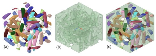
Figure 1.
The RVE model and its details: (a) BNNTs; (b) polymer matrix; and (c) the combination of polymer matrix and BNNTs.
Table 2.
Material properties of the scaffold.
2.3. Finite Element Analysis (FEA)
The RVE and scaffold model (Figure 2a) with characteristics listed in Table 3 were imported into the ANSYS as material designer and geometry. The material designer was connected to the engineering data in the FEA analysis system. The homogenous isotropic properties with the scaffold model were related to the geometry of the FEA analysis. Therefore, a scaffold featuring randomly distributed BNNTs was generated to analyse the mechanical properties.
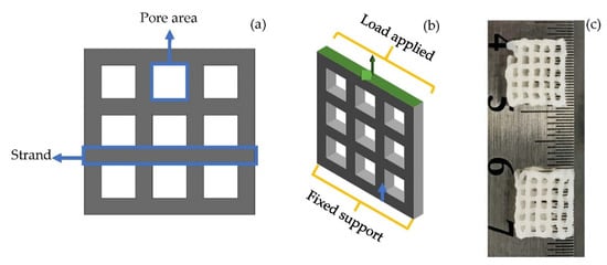
Figure 2.
(a) 3D scaffold designed for analysis; (b) applied boundary condition on scaffold model; (c) 3D-bioprinted lattice structured scaffold of BNNTs reinforced alginate and gelatin.
Table 3.
Characterisation of the scaffold.
2.4. Boundary Conditions
The investigation was carried in static load conditions with increase in load for each second up to 5 s on the scaffold. For the simulation, a transient plugin in ANSYS was used for the tension test. The displacement rate was kept at 2 mm/min based on a typical quasi-static loading rate for testing bone and biomaterials for tissue-engineering applications. The Poisson’s ratio was kept constant throughout the FEA. To predict the tensile properties, one end of the scaffold was fixed (blue arrow, Figure 2b), and the other end (green arrow, Figure 2b) was applied with load. The maximum von Mises stress required for deformation of the scaffold was calculated.
The porosity of the scaffold was calculated using Equation (1) as follows:
2.5. Experimental
According to previous report [48], the alginate, gelatin, and BNNTs hydrogel composite scaffolds were produced. Briefly, alginate (5 w/v%) and gelatin (6 w/v%) were mixed in deionised water through constantly stirring for 1 h. Later, BNNTs (1 w/v%) was slowly added into the alginate and gelatin solution and stirred for another 1 h at 60 °C. The obtained solution was loaded into a 3-mL syringe with attached 22-gauge nozzle. The syringe was fixed to a 3D bioprinter (Cellink INKREDIBLE+, Sweden). Afterwards, the scaffold was printed with 105 ± 5 kPa pressure (Figure 2c). The obtained grid-like, porous scaffold was crosslinked with 100 Mm calcium chloride solution and freeze-dried prior to the tension test. The freeze-dried samples were tested according to Oladapo et al.’s [49] described method for universal testing machine. The test was carried out in the tensile test method using INSTRON 5982 (INSTRON, USA) with a constant displacement of 0.5 mm/min at room temperature. The engineering stress and strain values obtained in the experiment were transformed into the true stress and true strain values corresponding to Equations (2) and (3).
where σ and ∈ represent the stress and strain of the material. The deformation rate was kept to be the same as in the simulation. However, the mesh relevance and element size were modified to obtain the most precise results.
3. Results
3.1. Mesh Generation
Mesh convergence is one of the concerns in the simulation process, as it can affect the accuracy of the results. Therefore, Solid 95 soft mesh was selected to mimic the scaffold structure, as it creates a smooth mesh and avoids simulation stress-convergence errors. The soft mesh automatically generates higher node elements in higher curvature areas without the need for mesh control. The element size of 0.2 mm (Figure 3) was used to obtain accurate results closer to the mechanical test results.
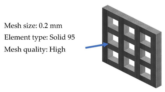
Figure 3.
Meshing of the scaffold model.
3.2. Mechanical properties
The von Mises distribution was shown in Figure 4a. The maximum (red arrows) and minimum stress (yellow arrows) concentration on the scaffolds when it was stretched are shown in Figure 4a. It is vital to recognize the stress concentration of a structure, as it will aid in suggesting areas of failures within the structure. The FEM results demonstrated that the scaffold underwent maximum stress at 2.7 MPa (Figure 4a). The corresponding moderate equivalent strain (Figure 4b) in the scaffold was shown at a higher rate of 6%.
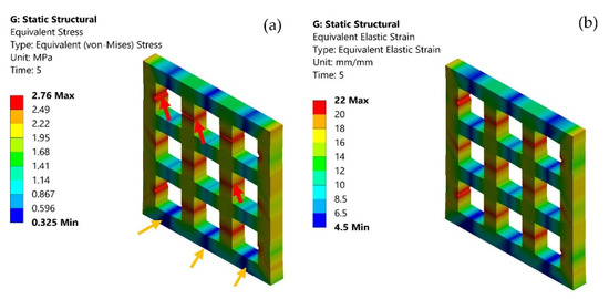
Figure 4.
(a) von Mises stress distribution on the scaffold model; maximum stress (red arrows), minimum stress (yellow arrows); and (b) elastic strain on the scaffold model.
Additionally, the stress-strain curves were compared with the experimental data. The plot graph of stress and strain in Figure 5 demonstrated the maximum experimental stress compared to the FEA predictions. However, both practical and simulation showed the maximum stress rate was attained at approximately 6%. Both FEA and experimental results showed the elastic region corresponding to the pore edge bending or face stretching. The second region was a plastic region corresponding to the progressive pore collapse due to the load applied. The fracture region corresponds to the pore’s failure at maximum stress of 2.7 MPa for FEA and 2.8 MPa for experimental data. The FEA and experimental plots showed a variation in plastic and fracture regions due to the variation of the load. Furthermore, in FEA, the material was considered isotropic. The percentage of error for FEA and experimental was approximately 4%. Li et al. [50] demonstrated sodium alginate, gelatin, and carbon nanotubes mechanical testing of circular scaffolds mechanical strength of 1.24 MPa. Serrano-Aroca et al. [51] reported alginate-graphene oxide composite hydrogel maximum stress at 8.98 ± 0.35 MPa. Similarly, the BNNTs-reinforced alginate and gelatin showed 2.8 MPa maximum stress. Additionally, the maximum strength of human soft tissues and hard tissues range between 0.01 MPa to 150 MPa [52,53,54]. Thus, it was evident that BNNTs-reinforced gelatin and alginate could be a potential scaffold for regenerating tissue with good pore interconnectivity as well as a good agreement between experimental and analysis.
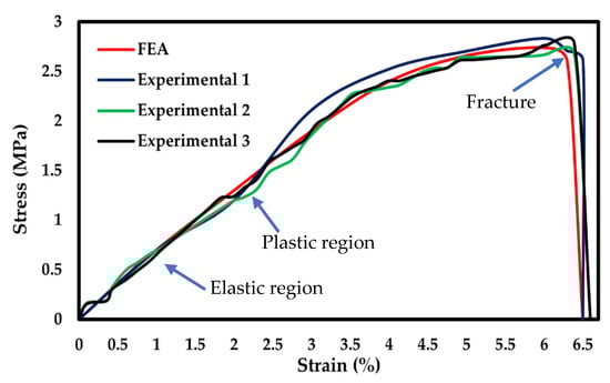
Figure 5.
Stress-strain curve comparison of FEA with experimental.
According to studies conducted by Ambu et al. [55], Smith et al. [56], and Maskery et al. [57], the smaller pore areas are adequate for FEA simulation compared with larger pore size. Hence, in this study, 2 × 2 mm2 pore areas were considered for simulation. The BNNTs-reinforced gelatin and alginate scaffold results indicated that the stress in the scaffold showed a homogeneous distribution at the fixed end and heterogeneous distribution at the pore area. The areas close to the pores have higher stress (Figure 6a, red arrows) concentration by default due to soft spots. The areas at the edges and corners have less stress concentration (Figure 6a, yellow arrows). The fracture occurred at the maximum stress point, as shown in Figure 6b (red arrow). The porous BNNTs-reinforced gelatin and alginate scaffold with the smallest pore size was an excellent combination to produce a scaffold with high mechanical properties while providing an excellent porosity (84%). Furthermore, an adequate pore size and porosity are important factors to the scaffold’s properties because the pores aid in cell proliferation and differentiation as well as encourage development of tissue structures [17,58,59].
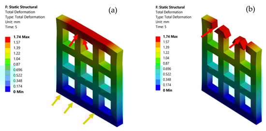
Figure 6.
(a) Total deformation of the scaffold model and (b) fractured area (red arrow) of the scaffold model.
4. Conclusions
In this paper, a FEM model combined with geometry and RVE was developed to analyse the mechanical behaviour of the porous scaffold for tissue-engineering applications. The scaffold was designed with regular pore interconnectivity and strand distance. Additionally, the analysed data were validated with experimental results of a 3D-printed scaffold. The simulation results showed that 2 × 2 mm2 pore size was found to play a significant role in determining the maximum stress region. The higher stress concentration areas were observed at the soft zones close to the pore area, considered default stress regions. The analysed maximum strength was obtained at 2.7 MPa and experimental at 2.8 MPa. The FEA and experimental stress-strain curves corresponded to each other and displayed analogous slopes and trends within the range. In addition, the investigation of lattice models with a random distribution of BNNTs in gelatin and alginate is both novel and helpful to the designer of 3D bioprinting, particularly in discovering the biomechanical properties. However, the findings are limited to uniform strand and pore size. Further work will focus on evaluating a widening type of pore sizes, strand directions, and widths with FEA and experiments.
Author Contributions
Conceptualization, A.B.K.; methodology, A.B.K.; software, A.B.K.; validation, A.B.K. and I.K.; formal analysis, A.B.K. and S.G.N.; investigation, I.K and W.K.; resources, I.K.; data curing, A.B.K. and S.G.N.; writing—original draft preparation, A.B.K.; writing—reviewing and editing, I.K and W.K.; visualization, A.B.K. and I.K.; supervision, I.K.; funding acquisition, I.K.; project administration, I.K. All authors have read and agreed to the published version of the manuscript.
Funding
This research received no external funding.
Institutional Review Board Statement
Not applicable.
Informed Consent Statement
Not applicable.
Data Availability Statement
Not applicable.
Acknowledgments
Vipulkumar Ishvarbhai Patel is acknowledged for his support and valuable feedback on methodology and analysis.
Conflicts of Interest
The authors declare no conflict of interest.
References
- Giannitelli, S.M.; Accoto, D.; Trombetta, M.; Rainer, A. Current trends in the design of scaffolds for computer-aided tissue engineering. Acta Biomater. 2014, 10, 580–594. [Google Scholar] [CrossRef] [PubMed]
- Melchels, F.P.W.; Barradas, A.M.C.; van Blitterswijk, C.A.; de Boer, J.; Feijen, J.; Grijpma, D.W. Effects of the architecture of tissue engineering scaffolds on cell seeding and culturing. Acta Biomater. 2010, 6, 4208–4217. [Google Scholar] [CrossRef] [PubMed] [Green Version]
- Pires, T.; Santos, J.; Ruben, R.B.; Gouveia, B.P.; Castro, A.P.G.; Fernandes, P.R. Numerical-experimental analysis of the permeability-porosity relationship in triply periodic minimal surfaces scaffolds. J. Biomech. 2021, 117, 110263. [Google Scholar] [CrossRef] [PubMed]
- Ibañez, R.I.R.; do Amaral, R.J.F.C.; Reis, R.L.; Marques, A.P.; Murphy, C.M.; O’Brien, F.J. 3D-Printed Gelatin Methacrylate Scaffolds with Controlled Architecture and Stiffness Modulate the Fibroblast Phenotype towards Dermal Regeneration. Polymers 2021, 13, 2510. [Google Scholar] [CrossRef] [PubMed]
- Karageorgi, V.; Kalpan, D. Porosity of 3D biomaterial scaffolds and osteogenesis. Biomaterials 2005, 26, 5474–5491. [Google Scholar] [CrossRef]
- Soufivand, A.A.; Abolfathi, N.; Hashemi, S.A.; Lee, S.J. Prediction of mechanical behavior of 3D bioprinted tissue-engineered scaffolds using finite element method (FEM) analysis. Addit. Manuf. 2020, 33, 101181. [Google Scholar] [CrossRef]
- Gómez, S.; Vlad, M.D.; López, J.; Fernández, E. Design and properties of 3D scaffolds for bone tissue engineering. Acta Biomater. 2016, 42, 341–350. [Google Scholar] [CrossRef]
- Adachi, T.; Osako, Y.; Tanaka, M.; Hojo, M.; Hollister, S.J. Framework for optimal design of porous scaffold microstructure by computational simulation of bone regeneration. Biomaterials 2006, 27, 3964–3972. [Google Scholar] [CrossRef]
- Oladapo, B.I.; Zahedi, S.A.; Ismail, S.O.; Olawade, D.B. Recent advances in biopolymeric composite materials: Future sustainability of bone-implant. Renew. Sustain. Energy Rev. 2021, 150, 111505. [Google Scholar] [CrossRef]
- Childs, P.G.; Boyle, C.A.; Pemberton, G.D.; Nikukar, H.; Curtis, A.S.G.; Henriquez, F.L.; Dalby, M.J.; Reid, S. Use of nanoscale mechanical stimulation for control and manipulation of cell behaviour. Acta Biomater. 2016, 34, 159–168. [Google Scholar] [CrossRef]
- Hao, M.; Wei, C.; Liu, X.; Ge, Y.; Cai, J. Quantitative evaluation on mechanical characterization of Ti6Al4V porous scaffold designed based on Weaire-Phelan structure via experimental and numerical analysis methods. J. Alloys Compd. 2021, 885, 160234. [Google Scholar] [CrossRef]
- Jin, Y.; Chai, W.; Huang, Y. Printability study of hydrogel solution extrusion in nanoclay yield-stress bath during printing-then-gelation biofabrication. Mater. Sci. Eng. C 2017, 80, 313–325. [Google Scholar] [CrossRef] [PubMed]
- Curti, F.; Stancu, I.-C.; Voicu, G.; Iovu, H.; Dobrita, C.-I.; Ciocan, L.T.; Marinescu, R.; Iordache, F. Development of 3D Bioactive Scaffolds through 3D Printing Using Wollastonite–Gelatin Inks. Polymers 2020, 12, 2420. [Google Scholar] [CrossRef] [PubMed]
- Holzwarth, J.M.; Ma, P.X. Biomimetic nanofibrous scaffolds for bone tissue engineering. Biomaterials 2011, 32, 9622–9629. [Google Scholar] [CrossRef] [Green Version]
- Müller, M.; Becher, J.; Schnabelrauch, M.; Zenobi-Wong, M. Nanostructured Pluronic hydrogels as bioinks for 3D bioprinting. Biofabrication 2015, 7, 35006. [Google Scholar] [CrossRef]
- Gong, Y.; Wang, F.; Al-Furjan, M.S.H.; Shan, L.; He, J.; Bian, X.; Bi, Z.; Liu, H.; Li, W.; Shao, H.; et al. Experimental Investigation and Optimal 3D Bioprinting Parameters of SA-Gel Porous Cartilage Scaffold. Appl. Sci. 2020, 10, 768. [Google Scholar] [CrossRef] [Green Version]
- Ostrowska, B.; Di Luca, A.; Moroni, L.; Swieszkowski, W. Influence of internal pore architecture on biological and mechanical properties of three-dimensional fiber deposited scaffolds for bone regeneration. J. Biomed. Mater. Res. Part A 2016, 104, 991–1001. [Google Scholar] [CrossRef]
- Sun, K.; Li, R.; Li, H.; Fan, M.; Li, H. Analysis and Demonstration of a Scaffold Finite Element Model for Cartilage Tissue Engineering. ACS Omega 2020, 5, 32411–32419. [Google Scholar] [CrossRef]
- Uth, N.; Mueller, J.; Smucker, B.; Yousefi, A.-M. Validation of scaffold design optimization in bone tissue engineering: Finite element modeling versus designed experiments. Biofabrication 2017, 9, 015023. [Google Scholar] [CrossRef] [Green Version]
- Mustafa, N.S.; Akhmal, N.H.; Izman, S.; Ab Talib, M.H.; Shaiful, A.I.M.; Omar, M.N.B.; Yahaya, N.Z.; Illias, S. Application of Computational Method in Designing a Unit Cell of Bone Tissue Engineering Scaffold: A Review. Polymers 2021, 13, 1584. [Google Scholar] [CrossRef]
- Rodríguez-Montaño, Ó.L.; Cortés-Rodríguez, C.J.; Uva, A.E.; Fiorentino, M.; Gattullo, M.; Manghisi, V.M.; Boccaccio, A. An Algorithm to Optimize the Micro-Geometrical Dimensions of Scaffolds with Spherical Pores. Materials 2020, 13, 4062. [Google Scholar] [CrossRef] [PubMed]
- De Santis, R.; Russo, T.; Rau, J.V.; Papallo, I.; Martorelli, M.; Gloria, A. Design of 3D Additively Manufactured Hybrid Structures for Cranioplasty. Materials 2021, 14, 181. [Google Scholar] [CrossRef] [PubMed]
- Mohonee, V.K.; Lim Goh, K.; Mishnaevsky, L.; Pasbakhsh, P. Capsule based self-healing composites: New insights on mechanical behaviour based on finite element analysis. Comput. Mater. Sci. 2021, 192, 110203. [Google Scholar] [CrossRef]
- Mirtaghavi, A.; Luo, J.; Muthuraj, R. Recent Advances in Porous 3D Cellulose Aerogels for Tissue Engineering Applications: A Review. J. Compos. Sci. 2020, 4, 152. [Google Scholar] [CrossRef]
- Miranda, P.; Pajares, A.; Guiberteau, F. Finite element modeling as a tool for predicting the fracture behavior of robocast scaffolds. Acta Biomater. 2008, 4, 1715–1724. [Google Scholar] [CrossRef]
- Hashemi, S.A.; Esmaeili, S.; Ghadirinejad, M.; Saber-Samandari, S.; Sheikhbahaei, E.; Kordjamshidi, A.; Khandan, A. Micro-Finite Element Model to Investigate the Mechanical Stimuli in Scaffolds Fabricated via Space Holder Technique for Cancellous Bone. ADMT J. 2020, 13, 51–58. [Google Scholar]
- Ali, D.; Sen, S. Finite element analysis of mechanical behavior, permeability and fluid induced wall shear stress of high porosity scaffolds with gyroid and lattice-based architectures. J. Mech. Behav. Biomed. Mater. 2017, 75, 262–270. [Google Scholar] [CrossRef]
- Bagde, A.D.; Kuthe, A.M.; Nagdeve, S.R.; Dahake, S.W.; Sapkal, P.S.; Daronde, S.B.; Lande, N.H.; Sarode, B.D. Geometric Modeling and Finite Element Simulation for Architecture Design of 3D Printed Bio-ceramic Scaffold Used in Bone Tissue Engineering. J. Indian Inst. Sci. 2019, 99, 361–374. [Google Scholar] [CrossRef]
- Patel, R.; Lu, M.; Diermann, S.H.; Wu, A.; Pettit, A.; Huang, H. Deformation behavior of porous PHBV scaffold in compression: A finite element analysis study. J. Mech. Behav. Biomed. Mater. 2019, 96, 1–8. [Google Scholar] [CrossRef]
- Jiang, T.; Shang, J.; Tang, L.; Wang, Z. Thickness optimization of auricular silicone scaffold based on finite element analysis. J. Mech. Behav. Biomed. Mater. 2016, 53, 397–402. [Google Scholar] [CrossRef]
- Blázquez-Carmona, P.; Sanz-Herrera, J.A.; Martínez-Vázquez, F.J.; Domínguez, J.; Reina-Romo, E. Structural optimization of 3D-printed patient-specific ceramic scaffolds for in vivo bone regeneration in load-bearing defects. J. Mech. Behav. Biomed. Mater. 2021, 121, 104613. [Google Scholar] [CrossRef] [PubMed]
- Agrawal, R.; Nieto, A.; Chen, H.; Mora, M.; Agarwal, A. Nanoscale Damping Characteristics of Boron Nitride Nanotubes and Carbon Nanotubes Reinforced Polymer Composites. ACS Appl. Mater. Interfaces 2013, 5, 12052–12057. [Google Scholar] [CrossRef] [PubMed]
- Chung, C.; Kim, Y.K.; Shin, D.; Ryoo, S.R.; Hong, B.H.; Min, D.H. Biomedical applications of graphene and graphene oxide. Acc. Chem. Res. 2013, 46, 2211–2224. [Google Scholar] [CrossRef]
- Fiedler, T.; Belova, I.V.; Murch, G.E.; Roether, J.A.; Boccaccini, A.R. Tailoring elastic properties of PLGA/TiO2 biomaterials. Comput. Mater. Sci. 2012, 61, 283–286. [Google Scholar] [CrossRef]
- Du, X.; Dehghani, M.; Alsaadi, N.; Nejad, M.G.; Saber-Samandari, S.; Toghraie, D.; Su, C.-H.; Nguyen, H.C. A femoral shape porous scaffold bio-nanocomposite fabricated using 3D printing and freeze-drying technique for orthopedic application. Mater. Chem. Phys. 2022, 275, 125302. [Google Scholar] [CrossRef]
- Weidt, D.; Figiel, Ł. Finite strain compressive behaviour of CNT/epoxy nanocomposites: 2D versus 3D RVE-based modelling. Comput. Mater. Sci. 2014, 82, 298–309. [Google Scholar] [CrossRef] [Green Version]
- Gaharwar, A.K.; Peppas, N.A.; Khademhosseini, A. Nanocomposite hydrogels for biomedical applications. Biotechnol. Bioeng. 2014, 111, 441–453. [Google Scholar] [CrossRef] [Green Version]
- Warheit, D.B. Comparative Pulmonary Toxicity Assessment of Single-wall Carbon Nanotubes in Rats. Toxicol. Sci. 2003, 77, 117–125. [Google Scholar] [CrossRef] [Green Version]
- Lam, C.-W. Pulmonary Toxicity of Single-Wall Carbon Nanotubes in Mice 7 and 90 Days after Intratracheal Instillation. Toxicol. Sci. 2003, 77, 126–134. [Google Scholar] [CrossRef] [Green Version]
- Kostoglou, N.; Tampaxis, C.; Charalambopoulou, G.; Constantinides, G.; Ryzhkov, V.; Doumanidis, C.; Matovic, B.; Mitterer, C.; Rebholz, C. Boron Nitride Nanotubes Versus Carbon Nanotubes: A Thermal Stability and Oxidation Behavior Study. Nanomaterials 2020, 10, 2435. [Google Scholar] [CrossRef]
- Sedigh, P.; Zare, A.; Montazeri, A. Evolution in aluminum applications by numerically-designed high strength boron-nitride/Al nanocomposites. Comput. Mater. Sci. 2020, 171, 109227. [Google Scholar] [CrossRef]
- Akesh Babu, K.; Cin, K.; Wei, K.; Ing, K.; Kakarla, A.B.; Kong, C.; Kong, W.; Kong, I. Synthesis and Characterization of Boron Nitride Nanotubes-Polycaprolactone Nanocomposite. Mater. Sci. Forum 2019, 951, 39–44. [Google Scholar] [CrossRef]
- Nagarajan, S.; Belaid, H.; Pochat-Bohatier, C.; Teyssier, C.; Iatsunskyi, I.; Coy, E.; Balme, S.; Cornu, D.; Miele, P.; Kalkura, N.S.; et al. Design of Boron Nitride/Gelatin Electrospun Nanofibers for Bone Tissue Engineering. ACS Appl. Mater. Interfaces 2017, 9, 33695–33706. [Google Scholar] [CrossRef] [PubMed]
- Ali, D.; Sen, S. Finite element analysis of the effect of boron nitride nanotubes in beta tricalcium phosphate and hydroxyapatite elastic modulus using the RVE model. Compos. Part B Eng. 2016, 90, 336–340. [Google Scholar] [CrossRef]
- Lu, X.; Nautiyal, P.; Bustillos, J.; Loganathan, A.; Zhang, C.; Chen, Y.; Boesl, B.; Agarwal, A. Hydroxylated boron nitride nanotube-reinforced polyvinyl alcohol nanocomposite films with simultaneous improvement of mechanical and thermal properties. Polym. Compos. 2020, 41, 5182–5194. [Google Scholar] [CrossRef]
- Ceccaldi, C.; Fullana, S.G.; Alfarano, C.; Lairez, O.; Calise, D.; Cussac, D.; Parini, A.; Sallerin, B. Alginate Scaffolds for Mesenchymal Stem Cell Cardiac Therapy: Influence of Alginate Composition. Cell Transplant. 2012, 21, 1969–1984. [Google Scholar] [CrossRef] [Green Version]
- Czerner, M.; Fellay, L.S.; Suárez, M.P.; Frontini, P.M.; Fasce, L.A. Determination of Elastic Modulus of Gelatin Gels by Indentation Experiments. Procedia Mater. Sci. 2015, 8, 287–296. [Google Scholar] [CrossRef] [Green Version]
- Kakarla, A.B.; Kong, I.; Turek, I.; Kong, C.; Irving, H. Printable gelatin, alginate and boron nitride nanotubes hydrogel-based ink for 3D bioprinting and tissue engineering applications. Mater. Des. 2022, 213, 110362. [Google Scholar] [CrossRef]
- Oladapo, B.I.; Ismail, S.O.; Adebiyi, A.V.; Omigbodun, F.T.; Olawumi, M.A.; Olawade, D.B. Nanostructural interface and strength of polymer composite scaffolds applied to intervertebral bone. Colloids Surfaces A Physicochem. Eng. Asp. 2021, 627, 127190. [Google Scholar] [CrossRef]
- Li, L.; Qin, S.; Peng, J.; Chen, A.; Nie, Y.; Liu, T.; Song, K. Engineering gelatin-based alginate/carbon nanotubes blend bioink for direct 3D printing of vessel constructs. Int. J. Biol. Macromol. 2020, 145, 262–271. [Google Scholar] [CrossRef]
- Serrano-Aroca, Á.; Iskandar, L.; Deb, S. Green synthetic routes to alginate-graphene oxide composite hydrogels with enhanced physical properties for bioengineering applications. Eur. Polym. J. 2018, 103, 198–206. [Google Scholar] [CrossRef] [Green Version]
- Sakuma, I.; Nishimura, Y.; Chui, C.K.; Kobayashi, E.; Inada, H.; Chen, X.; Hisada, T. In Vitro Measurement of Mechanical Properties of Liver Tissue under Compression and Elongation Using a New Test Piece Holding Method with Surgical Glue BT—Surgery Simulation and Soft Tissue Modeling; Ayache, N., Delingette, H., Eds.; Springer: Berlin/Heidelberg, Germany, 2003; pp. 284–292. [Google Scholar]
- Pervin, F.; Chen, W.W.; Weerasooriya, T. Dynamic compressive response of bovine liver tissues. J. Mech. Behav. Biomed. Mater. 2011, 4, 76–84. [Google Scholar] [CrossRef] [PubMed]
- Holzapfel, G.A. Biomechanics of Soft Tissue. In Handbook of Materials Behavior Models; Elsevier: Amsterdam, The Netherlands, 2001; pp. 1057–1071. [Google Scholar]
- Ambu, R.; Morabito, A. Porous Scaffold Design Based on Minimal Surfaces: Development and Assessment of Variable Architectures. Symmetry 2018, 10, 361. [Google Scholar] [CrossRef] [Green Version]
- Smith, M.; Guan, Z.; Cantwell, W.J. Finite element modelling of the compressive response of lattice structures manufactured using the selective laser melting technique. Int. J. Mech. Sci. 2013, 67, 28–41. [Google Scholar] [CrossRef]
- Maskery, I.; Aremu, A.O.; Parry, L.; Wildman, R.D.; Tuck, C.J.; Ashcroft, I.A. Effective design and simulation of surface-based lattice structures featuring volume fraction and cell type grading. Mater. Des. 2018, 155, 220–232. [Google Scholar] [CrossRef]
- Bružauskaitė, I.; Bironaitė, D.; Bagdonas, E.; Bernotienė, E. Scaffolds and cells for tissue regeneration: Different scaffold pore sizes—Different cell effects. Cytotechnology 2016, 68, 355–369. [Google Scholar] [CrossRef] [Green Version]
- Griffon, D.; Sedighi, M.; Schaeffer, D.; Eurell, J.; Johnson, A. Chitosan scaffolds: Interconnective pore size and cartilage engineering. Acta Biomater. 2006, 2, 313–320. [Google Scholar] [CrossRef] [PubMed]
Publisher’s Note: MDPI stays neutral with regard to jurisdictional claims in published maps and institutional affiliations. |
© 2022 by the authors. Licensee MDPI, Basel, Switzerland. This article is an open access article distributed under the terms and conditions of the Creative Commons Attribution (CC BY) license (https://creativecommons.org/licenses/by/4.0/).