Article

On the Machining Temperature and Hole Quality of CFRP Laminates When Using Diamond-Coated Special Drills

1
State Key Laboratory of Mechanical System and Vibration, School of Mechanical Engineering, Shanghai Jiao Tong University, Shanghai 200240, China
2
Department of Mechanical Engineering, University of Aveiro, Campus Santiago, 3810-193 Aveiro, Portugal
*
Author to whom correspondence should be addressed.
J. Compos. Sci. 2022, 6(2), 45; https://doi.org/10.3390/jcs6020045
Submission received: 18 January 2022 / Revised: 26 January 2022 / Accepted: 29 January 2022 / Published: 1 February 2022
(This article belongs to the Special Issue Manufacturing of Fibrous Composites for Engineering Applications)

Abstract

:
Carbon fiber reinforced polymers (CFRPs) are attractive engineering materials in the modern aerospace industry, but possess extremely poor machinability because of their inherent anisotropy and heterogeneity. Although substantial research work has been conducted to understand the drilling behavior of CFRPs, some critical aspects related to the machining temperature development and its correlations with the process parameters still need to be addressed. The present paper aims to characterize the temperature variation and evolution during the CFRP drilling using diamond-coated candlestick and step tools. Progression of the composite drilling temperatures was recorded using an infrared thermography camera, and the hole quality was assessed in terms of surface morphologies and hole diameters. The results indicate that the maximum drilling temperature tends to be reached when the drill edges are fully engaged into the composite workpiece. Then it drops sharply as the tool tends to exit the last fiber plies. Lower cutting speeds and lower feed rates are found to favor the reduction of the maximum composite drilling temperature, thus reducing the risk of the matrix glass transition. The candlestick drill promotes lower magnitudes of drilling temperatures, while the step drill yields better surface morphologies and more consistent hole diameters due to the reaming effects of its secondary step edges.

1. Introduction

In recent decades, carbon fiber reinforced polymers (CFRPs) have been receiving immense attention in diverse engineering fields due to their superior properties and unique functionality [1,2,3,4]. This can be seen by their widespread applications for fabricating the main load-bearing components in the modern aerospace industries. For instance, CFRPs are extensively used in the wing boxes, horizontal and vertical stabilizers, and wing panels of large commercial aircrafts, such as Airbus A380 and Boeing 787 [4,5]. Generally, CFRPs feature two typical constituents, namely reinforcing fibers and an impregnating matrix, which show completely disparate behaviors [2,6]. The composites are characterized by high specific mechanical/physical properties, being a promising alternative to conventional metallic alloys and steels. Contrary to isotopic materials, CFRP composites generally exhibit a heterogeneous structure and anisotropic behavior, being regarded as a rather difficult-to-cut material. Although most CFRP components are fabricated to near-net shapes by molding processes, mechanical machining has become a compulsory operation in order to achieve desired dimensional accuracy and target quality attributes for final composite products [7,8,9,10]. However, the inherent anisotropy and heterogeneity of fibrous composites complicate the chip separation process and tend to cause extremely undesirable machining consequences such as severe surface damage, rapid tool wear, increased cutting costs. Meanwhile, the machinability of CFRPs is fiber-orientation dependent, owing to the varying fiber fracture mechanisms associated with the fiber cutting angle. It has been reported by previous investigations that interrelated chip separation modes such as bending-induced fractures, shear-induced fractures, fiber buckling, and interfacial debonding occur for the cutting of fibrous composites [11,12,13,14]. These unique characteristics result in the poor machinability of CFRP materials, posing tremendous challenges to modern manufacturing sectors. Among the secondary machining operations, drilling is the most frequently-used operation for the cutting of CFRPs due to the need to create boreholes for assembling different composite parts into final products. It is roughly estimated that the range of the number of holes required by a commercial aircraft is up to 1.5–3 million, while a jet fighter requires as many as 300,000 holes [4,6]. Thus, from the manufacturers’ point of view, the drilling process becomes essential in the final acceptance of composite parts. However, it is rather challenging to drill CFRPs with desired hole quality and target dimensional accuracy. This is due to the varying chip removal modes associated with the changeable fiber cutting angle and the high abrasiveness of the reinforcing fibers. Some of the critical issues encountered in CFRP drilling include drilling-induced delamination, glass transition failure of the composite matrix, poor dimensional accuracy, rapid tool wear, etc. Apart from the mechanical force effects, cutting heat and resulting temperature development also play a vital role in the surface integrity of CFRP materials. In particular, high temperatures can be easily accessed in the drilling processes due to the semi-enclosed environment of the chip separation, leading to poor heat dissipation. Excessive drilling temperatures promoted at the tool–composite interface can cause severe degradations of the composite properties, debonding of the fiber-matrix interfaces, and the glass transition of the matrix base [15,16,17,18]. Therefore, studies dealing with temperature initiation and progression are very meaningful to achieve active control of the thermal effects for the drilling of CFRP materials.
To address the drilling issues of CFRPs, a large amount of research work has been carried out worldwide by scholars [10,19,20,21,22,23,24,25,26,27,28,29,30,31,32,33,34,35], covering a variety of aspects involving drilling forces, drilling-induced damages, tool wear, etc. Some drilling-induced damage, including delamination, hole dimensional inaccuracy, surface roughness, fiber pullouts, and uncut fibers, have been investigated in the scientific literature [19,20]. For instance, Davim and Reis [21,22] were among the earliest to deal with the drilling behavior of CFRP composite laminates. In their work, the correlations between the cutting velocity and feed rate with the machining power, specific cutting pressure, and delamination factor were established. The authors stated that both the cutting speed and the feed rate positively affected the progression of the delamination factor, and the use of brad spur drills favored the reduction of drilling-induced delamination. Bonnet et al. [24] studied the local feed force and its consequences on the exit hole damage during CFRP drilling. It was found that the fiber cutting modes changed dynamically with the composite sequence, and the local feed forces generated on the hole bottom could be correlated with the delaminating aspects. Su et al. [28] addressed the thrust forces and delamination issues when drilling CFRPs using a tapered drill-reamer and found that the drilling parameters significantly affected the maximum thrust force measured in the drilling stage instead of the reaming stage. Ameur et al. [29] conducted drilling studies on CFRP materials using different types of tool materials. The authors stated that both the drilling thrust force and the delamination factor were primarily influenced by the tool material and the feed rate, while the hole cylindricity errors were mainly affected by the spindle speed. Rawat and Attia [31] studied the wear behavior of carbide tools during the high-speed drilling of CFRP laminates, and observed that chipping and abrasion were the main wear modes controlling the deterioration of carbide drills. Faraz et al. [32] highlighted the wear phenomenon of cutting-edge rounding (CER) for CFRP drilling and introduced the CER value for the quantification of drill wear. Wang et al. [33] investigated the wear progression of coated tools while drilling CFRP laminates. The authors pointed out that the dominant wear type was dulling or blunting of the cutting edge during CFRP drilling. The use of a diamond coating could significantly reduce the edge rounding wear, while the AlTiN coating failed to protect the drill due to its oxidation during machining. A critical review conducted by Ismail et al. [34] offered a clear understanding of the current advances in drilling composite materials, which focused on the aspects of tool geometries, materials, and parametric designs. Fu et al. [35] and Kubher et al. [36] investigated the temperature characteristics in drilling unidirectional (UD) and multidirectional (MD) CFRPs. Due to the associated temperature effects, utilizing MD CFRPs could result in more difficulties in achieving high drilling qualities than UD CFRPs at certain fiber cutting angles. Through the literature survey, although substantial research work has been conducted to understand the drilling behavior of CFRP composites, most of the studies are focused on the analysis of force-related effects, such as drilling thrust forces, delamination damage, hole quality, and tool wear issues. Even though there are some papers that have already addressed the temperature issues for CFRPs, very limited literature has been reported to deal with the temperature variations in drilling high-strength CFRPs with special drills. Moreover, some critical issues related to the machining temperature development and its correlations with the drilling parameters still need to be carefully addressed. Hence, the current work performed in the paper can supplement expertise and knowledge regarding the drilling temperature issues for high-strength CFRP composites. Its novelty lies in identifying the evolution law of the drilling temperature following the entire composite machining operation and in clarifying the parametric effects on the temperature development. Moreover, a particular focus is placed on the evaluation of different special drills for CFRP drilling and on the quantification of hole geometrical accuracy under varying drilling conditions. The experimental results were discussed with respect to the process parameters used. The paper is intended to offer a better understanding of the thermal behavior of CFRP laminates when subjected to the drilling operation.

2. Experimental Procedures

In the present work, machining studies were conducted on the multidirectional CFRP laminates fabricated by high-strength T700 carbon fibers and FRD-YZR-03 epoxy resin. The main composition and basic mechanical properties of the examined CFRP laminates are summarized in Table 1 and Table 2, respectively. The composite plate had a total size of 300 mm (length) × 200 mm (width) × 6.60 mm (thickness), which was fabricated by the hand lay-up molding technology. The drilling experiments were performed on a DMU 70 V CNC machining center following a full factorial design of experiments by using candlestick and step drills. The experimental setup for the drilling tests is shown in Figure 1. The input process parameters consist of three levels for the cutting speed (Vc = 40, 80, and 120 m/min) and three levels for the feed rate (f = 0.06, 0.09, and 0.12 mm/rev).
Both drills were diamond-coated special tools featuring an 8.0 mm diameter, a 30° helix angle, and a 90° point angle dedicated to delamination suppression and anti-abrasion wear during composite drilling. The detailed morphologies of the candlestick and step drills are shown in Figure 2. The candlestick drill featured three protruding tips, including one centering tip and two peripheral tips, which could significantly reduce the drilling thrust force and ensure the sharp flank cutting edges, whereas the step drill was designed following a step-control scheme involving a first step to create a pilot hole and a secondary step to ream the hole surface to the final diameter. Moreover, the examined step drill featured a ratio of the primary diameter (7.8 mm) to the second diameter (8.0 mm) of 0.975. The small difference between the primary and secondary diameters mainly aimed to let the secondary step edges have a reaming action on the previously cut hole surfaces by the first step drill, as a very small chip removal volume is involved in such step drilling. During the drilling operation, the FLIR A615 infrared thermography camera (IFTC), which featured a working temperature from −20 to 2000 °C and an image acquisition frequency from 50 to 200 Hz, was utilized to in-situ record the temperature development under varying drilling conditions. A similar method was applied by Xu et al. [37], which proved that the temperature measurement chain in the current experiment is capable of measuring the changes in the cutting temperature. The temperature resolution of the equipment was less than 0.05 °C, which guaranteed the accuracy and reliability of the monitored data. The accurate measurements of the cutting temperature by the thermographic camera were also carefully guaranteed by the calibration of emissivity value parameters set in the software. Additionally, an emissivity value of 0.85 was adopted for the composites drilling, according to the recommendations of the infrared thermography camera manufacturer. Moreover, to make the temperature measurements more reliable, all of the composite holes were drilled with a 1.0 mm distance close to the edge of the workpiece. After the completion of the drilling operations, the hole wall morphologies were characterized using the ZEISS confocal laser scanning microscope (CLSM). Finally, the average diameters at the entrance, middle, and exit sides of CFRP holes were measured using a SOLEX EUA coordinate measuring machine (CMM). The obtained results were correlated with the drill bits and the input process parameters.

3. Results and Discussion

3.1. Characterization of Drilling Temperatures

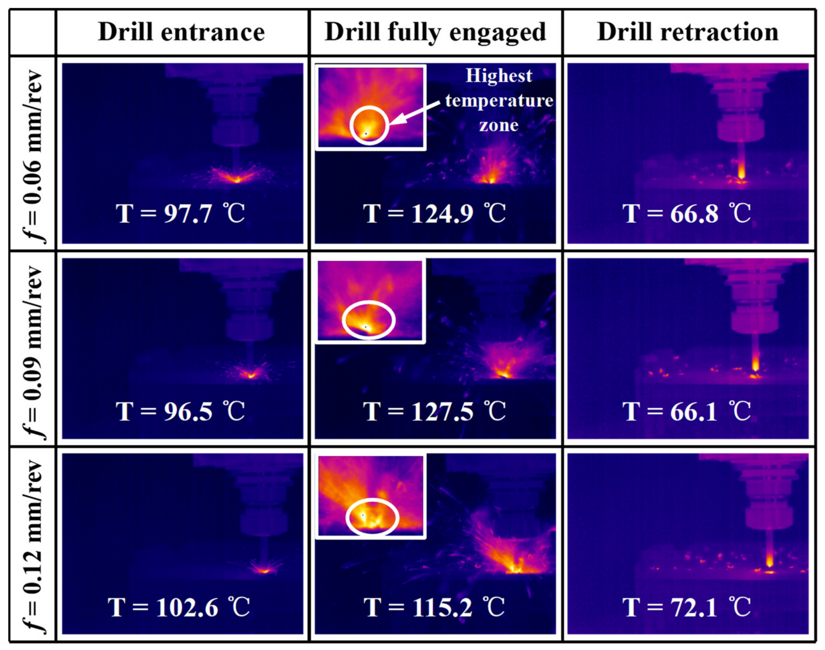
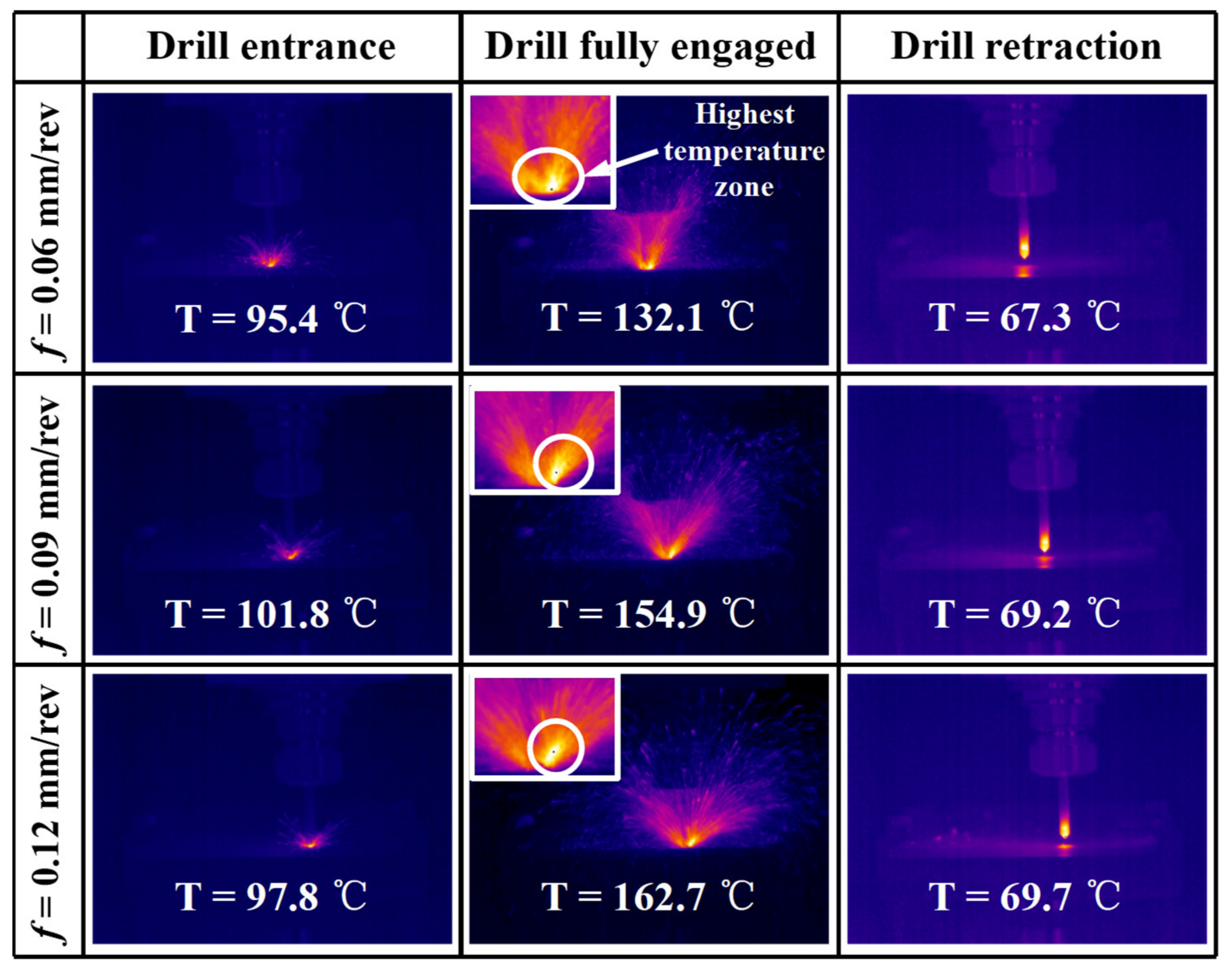
Machining temperature is a characteristic phenomenon of heat accumulation resulting from the tool–work interaction following the material separation process. When dealing with the hole-making processes of CFRP composites, drilling temperature is a critical issue that has to be carefully addressed, as high levels of temperatures can be easily accessed due to the poor heat dissipation of the drill–composite interaction. Additionally, high temperatures are extremely detrimental to the surface integrity and mechanical properties of cut composite holes as they can cause degradation of the composite properties, debonding of the fiber/matrix interface, or even the glass transition failure of the matrix base. Therefore, it is essential to characterize the variation laws of the temperature rise and progression during the machining of CFRP laminates. Figure 3 and Figure 4 show the recorded thermal images of the drilling temperature development under varying feed rates for the candlestick and step drills, respectively, during CFRP machining. It is clear that the temperature progression characteristics can be divided into three stages with respect to the tool–work interaction. At the early stage, the drill edges start to attack the composite laminate, and a large amount of cutting heat is progressively generated through the tool–chip and tool–work interactions. As brittle fracture dominates the chip separation of the carbon/epoxy composites, more cutting heat is likely to accumulate within a very narrow tool–chip interface, resulting in a high temperature rise as the drill tends to penetrate inside the composite. At the drill entrance stage, moderate levels of drilling temperatures are produced for both the candlestick and step drills. Meanwhile, with the ongoing tool advancement, the drill edges are fully engaged in the cutting of the fiber/epoxy material. In such circumstances, peak values of drilling temperatures are identified through the thermal image examinations for both drills used. Due to the heat accumulation effects and the full drill interaction with the composite material, the maximum temperature is reached, which indicates the highest risk of occurrence of the thermally-induced damage onto the internal composite hole walls. In most cases, the candlestick drills are found to produce relatively lower values of drilling temperatures than the step drills, particularly under the full drill–work interaction stage, as depicted in Figure 3 and Figure 4. Additionally, increasing the feed rate tends to elevate the maximum temperatures at the full tool engagement stage, due to the increased amount of frictional heat generated as the feed rate rises. Eventually, when the tool retracts from the composite workpiece, the drilling temperature appears to decrease dramatically because of the effective heat dissipation and air cooling of the tool–work system. It is also worth noting that both the candlestick and step drills yield comparable values of drilling temperatures at the drill retraction stage while machining the CFRP laminates.
Figure 5 also shows the comparative evolution of the drilling temperatures in terms of the cutting time (t) following a complete CFRP drilling process for both types of special tools. It is clear that the drilling temperature signals fluctuate significantly during the composite removal process, which exhibits a rapidly increasing trend at the drill entrance stage when the tool starts to attack the composite specimen. Then, the temperature signals for both drills appear to decrease gradually with the tool advancement as the drill edges start to exit the last composite plies, resulting in reduced frictional heat generation following the chip removal process. The previous investigation done by Fu et al. [35] revealed the complex drill-exit temperature characteristics for UD and MD CFRPs, and similar temperature changes were identified in their work. The maximum drilling temperatures for both drills seemed to be reached at around t = 0.5 s under the tested process parameters. The corresponding feed depth of the time is about 2.8 mm after the calculation using the time, feed rate, and cutting speed. Moreover, the candlestick drill is found to promote lower levels of peak drilling temperatures than the step drill. Figure 6 presents the comparison of the maximum temperatures recorded in the CFRP drilling between the two types of drills. Note that the maximum temperatures denoted herein signify the average value of the highest temperature range during the composite drilling. The results also indicate that the candlestick drills generally yield lower drilling temperatures than the step drills for all of the cutting conditions examined. This is due to the two protruding tips of the candlestick drill along the drill periphery that reduce the frictional heat generation and improve the heat dissipation at the tool–chip interactions. Additionally, the cutting speed definitely shows a positive impact on the progression of drilling temperatures for both tools, except for the abnormal temperature data at Vc = 40 m/min for the step drill. The phenomenon is associated with the intensified friction of the tool–composite interaction when the cutting speed increases. Moreover, increasing the feed rate appears to raise the drilling temperatures for the two special drills when machining the CFRP materials.

3.2. Hole Wall Morphologies

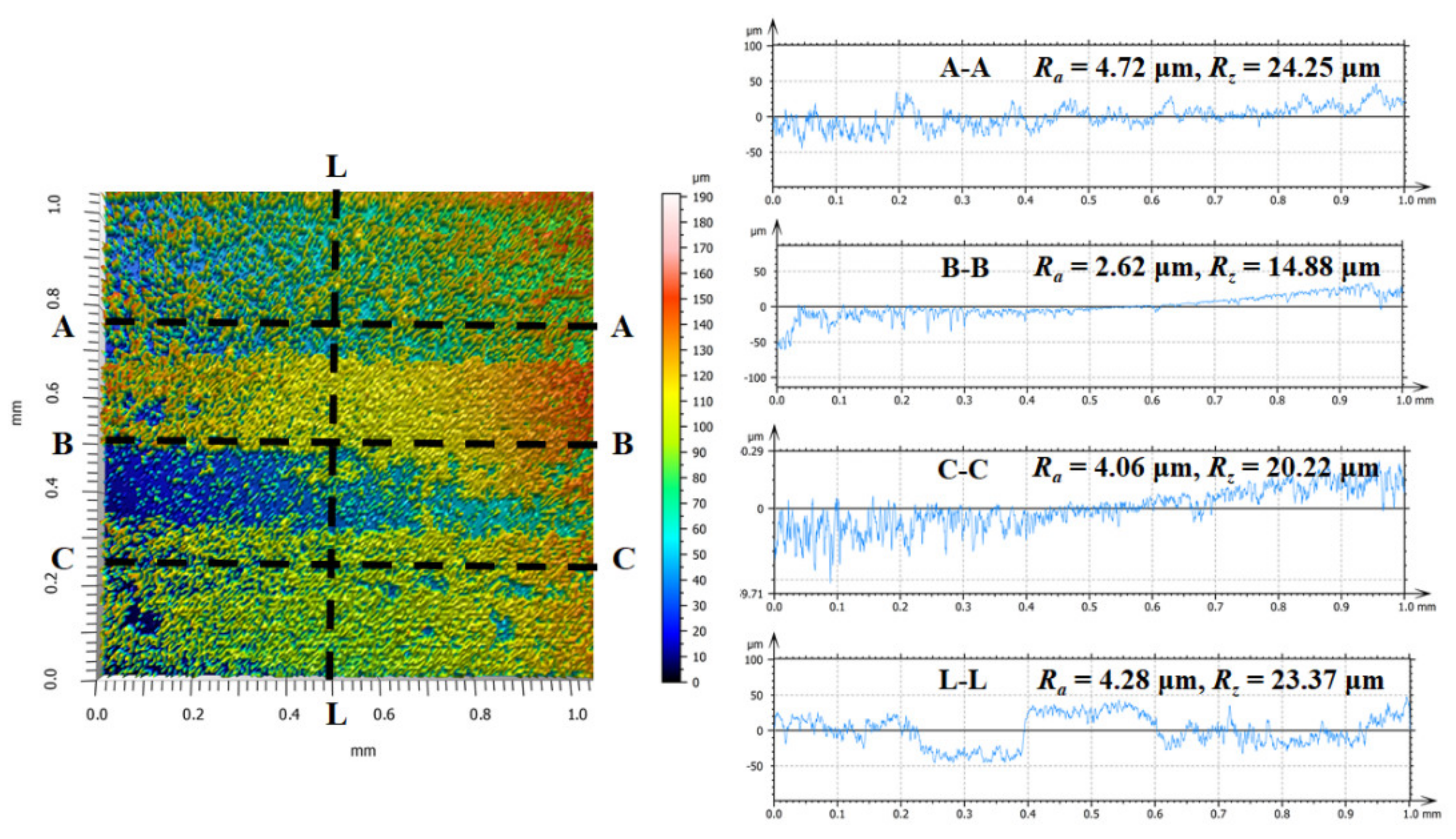
Machining of fibrous composites differs significantly from the cutting of isotropic metals and steels due to the varying chip separation mechanisms associated with the fiber orientation. The material removal complicates the surface generation of hole walls for the composites under drilling operations. Hole wall morphologies can be considered as one of the most important criteria in assessing the quality attributes of drilled CFRP composites. In general, it is rather difficult to generate smooth surface morphologies, as the material removal mode changes dynamically with the drill rotation during the hole-making process. Figure 7, Figure 8, Figure 9 and Figure 10 show the topographies of the CFRP hole walls produced by the two types of drills under the fixed cutting conditions (Vc = 120 m/min and f = 0.09 mm/rev). Figure 7, Figure 8, Figure 9 and Figure 10 all feature the same fiber orientations. From Figure 7, surface flaws due to interlaminar cracking are noted, which feature deep blue colored zones. The finely-cut composite surfaces mainly exist in areas involving the shear-induced fractures of fiber plies. Additionally, the profiles of four circular arc curves at the A–A, B–B, C–C, and L–L cross-sections are plotted in Figure 7 and Figure 9. It is noted that the surface profiles fluctuate significantly along both the radial and axial directions of the holes, which is due to the inherent variations in the surface of the fibers and the matrix. Additionally, the average surface roughness values (Ra) of the selected cross-sections mainly range from 5.00 to 6.29 μm along the hole radial direction, while Ra reaches its maximum value toward the hole axial direction at the L–L cross-section. This is due to the significant disparity in fiber orientation between adjacent fiber plies toward the composite thickness direction.
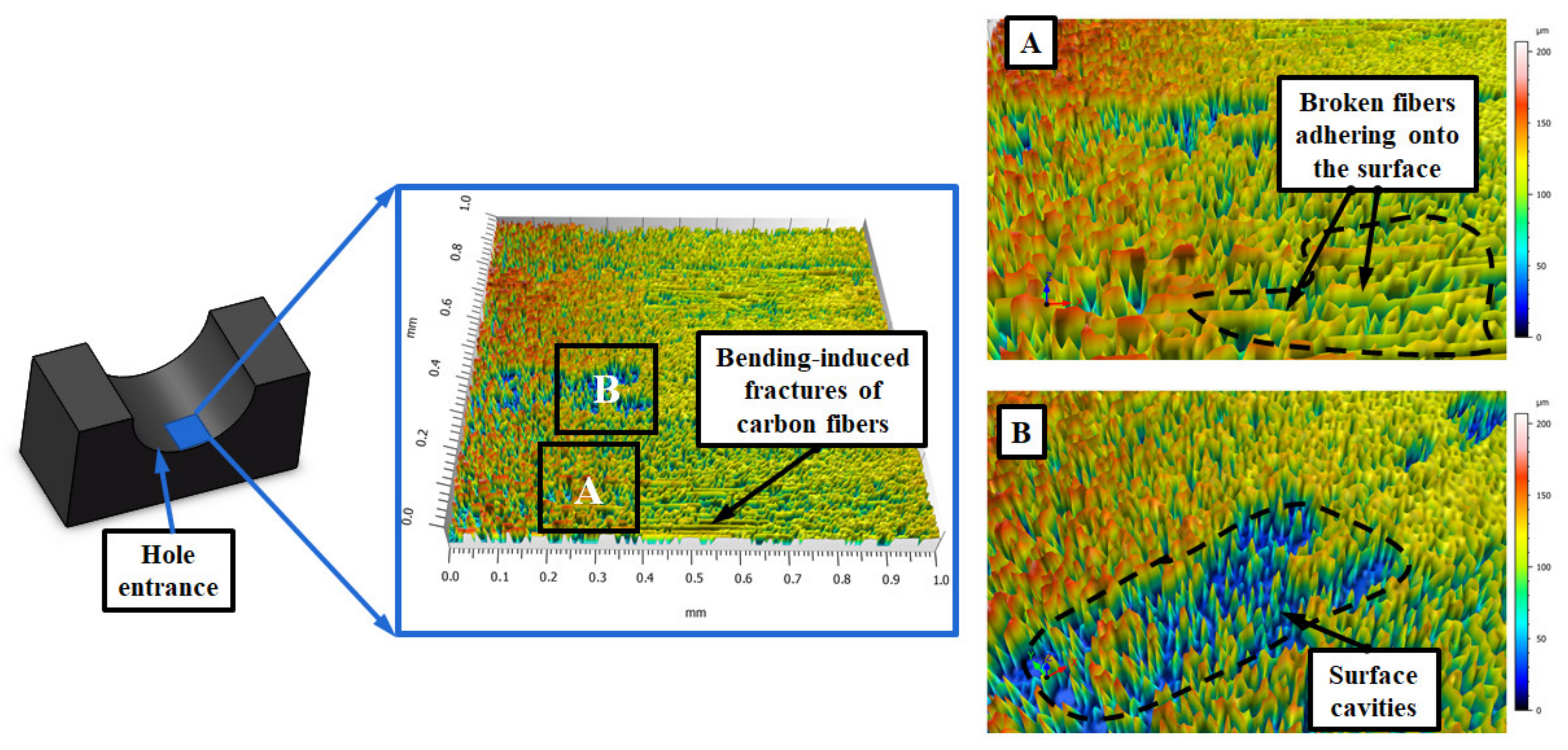
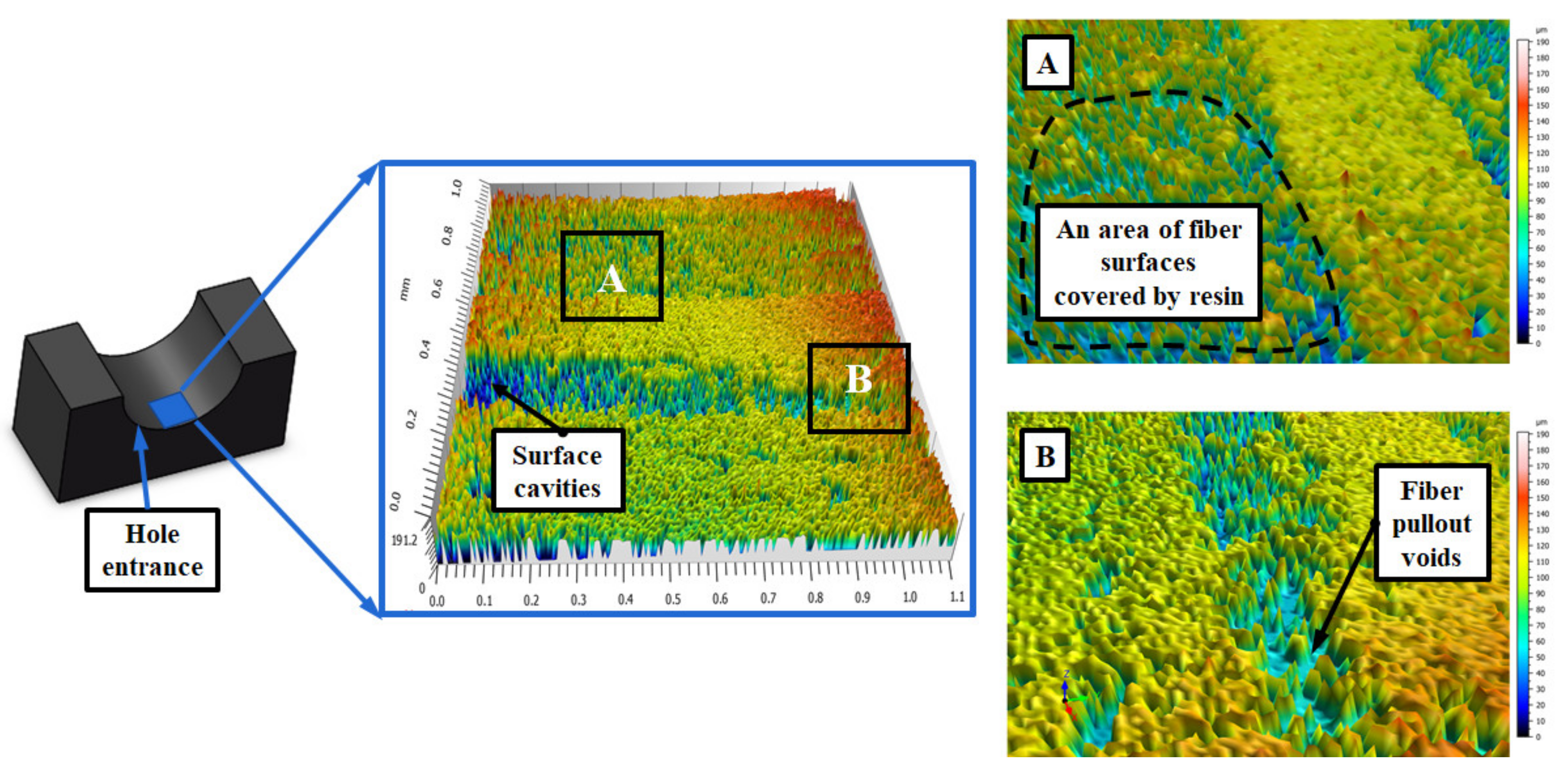
With respect to Figure 8, it shows the three-dimensional topographies of cut hole walls at the entrance side. It is evidenced that the cut CFRP hole morphologies feature smooth fiber surfaces containing a certain degree of surface cavities. In contrast, the hole wall morphologies produced by the step drill appear to be much better than those cut by the candlestick drill. As depicted in Figure 9, the Ra values of the four selected cross-sections are relatively lower than those gained by the candlestick drill. The phenomenon is due to the reaming effects of the secondary step edges, indicating the superiority of the step tools in achieving a better hole surface finish than the candlestick tools while machining the CFRP laminates. Moreover, the surface defects residing within the composite hole cut by the step drill mainly include surface cavities due to the loss of matrix, resin smearing, and fiber pullout voids, as shown in Figure 10. Note that the previous research carried out by Kubher et al. [36] addressed the evolution of in-situ cutting temperature and machining forces during the conventional drilling of MD CFRP laminates. Similar surface defects, including resin smearing and bending-induced fracture of carbon fibers, could be found in the research. For both drills in the current investigation, no significant evidence of interlaminar delamination at the hole entrance side is identified through the CLSM examination.

3.3. Hole Diameter

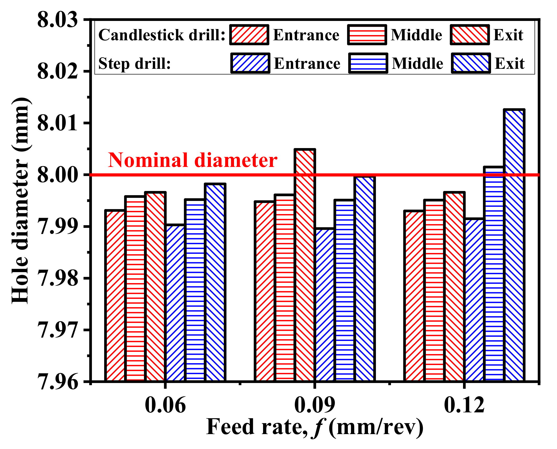
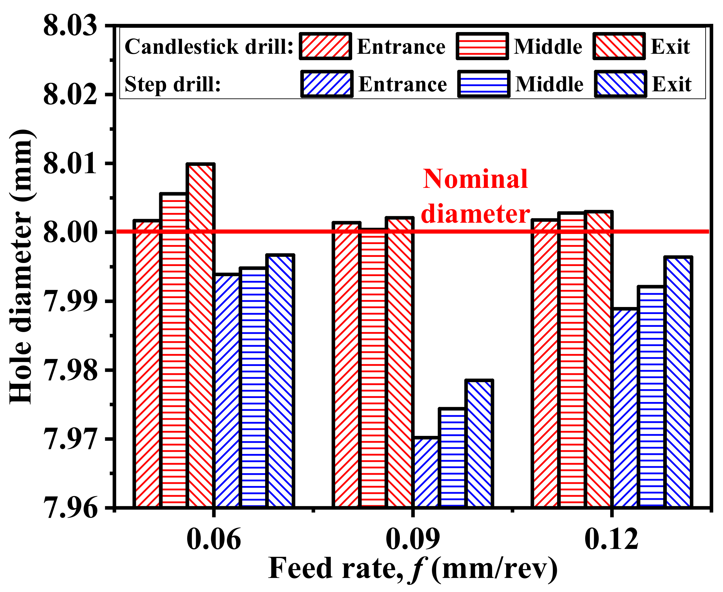
In drilling CFRP composites, diameter value is an essential criterion for evaluating the hole geometrical accuracy, which determines the assembly performance of the composite parts. In the current work, the average diameters at the entrance, middle, and exit sides of cut CFRP holes were measured and correlated with the process parameters and drill bits used. The obtained results are depicted in Figure 11, Figure 12 and Figure 13. Both the cutting speed and the feed rate have a significant impact on the variations of the hole diameters, irrespective of the measuring side. Under the lowest speed conditions (Vc = 40 m/min), increasing the feed rate tends to enlarge the cut hole diameters, particularly for the step drills (Figure 11). In most cases, undersized holes are generally produced by the two drills when Vc = 40 m/min. It is worth noting that the diameters measured at the exit side show the largest value, followed by those measured at the middle and entrance sides, regardless of the drill bits and process parameters used. The phenomenon indicates a wedge-shaped cylindrical surface of cut hole walls from the entrance to the exit side due to the intensified tool vibration arising from the decreased stiffness of remaining fiber plies as the fiber layers become much thinner with the tool advancement in drilling. When the moderate speed is used (Vc = 80 m/min), the feed rate fails to show a clear effect on the variations of the hole diameters. In particular, more consistent holes close to the nominal diameter value are promoted by the step drills at the feed rate of 0.09 mm/rev (Figure 12). With respect to the highest speed conditions (Vc = 120 m/min), typically, oversized holes are produced by the candlestick drills, and undersized holes are generated by step drills, as shown in Figure 13. Under such conditions, more consistent holes are created by the candlestick drill at the feed rate of 0.09 mm/rev. Finally, increasing the cutting speed seems to enlarge the hole diameters for the candlestick drills, but tends to decrease the hole diameters for the step drills. In general, to produce consistent holes close to the nominal diameter, the highest speed and moderate feed values are suggested for the candlestick drills, while moderate speed and lower feed values are recommended for the step drills.

4. Conclusions

This paper deals with the drilling behavior of CFRP composite laminates using diamond-coated special drills. Machining studies were conducted following a full factorial design of experiments. The composite machinability was evaluated, focusing on the machining temperature characteristics and hole quality attributes under varying conditions. The work addresses the temperature variations and progressions during the CFRP drilling. An attempt was made to assess the performances of different special drills and to quantify the hole geometrical accuracy in the CFRP drilling. Based on the results acquired, the following conclusions can be drawn.
  • Development of the drilling temperature can be roughly divided into three stages in terms of the tool–work interaction. In general, the maximum temperature values can be attained when the drill edges are fully engaged into the composite workpiece. The progression of the composite drilling temperature basically shows a high sensitivity to the input process parameters. In most cases, both the cutting speed and the feed rate exhibit a positive impact on the temperature rise for all of the drills examined.
  • The candlestick drills are found to produce lower magnitudes of drilling temperatures than the step ones. To suppress the temperature progression, low cutting speeds and low feed rates are recommended for the drilling of CFRP composites.
  • The cut CFRP hole morphologies are characterized by finely-cut fiber surfaces along with a certain degree of surface cavities due to the loss of matrix. The step drill produces better hole wall morphologies and lower surface roughness values than the candlestick drill due to the reaming effects of its secondary step edges. The main surface defects residing within the cut composite holes include surface cavities, resin smearing, and fiber pullout voids.
  • A wedge-shaped cylindrical surface is noted for the cut composite hole wall due to the intensified tool vibration arising from the decreased stiffness of the last fiber plies with the tool advancement. Both the process parameters significantly affect the variations of the hole diameters, irrespective of the measuring side. In general, the highest speed and moderate feed are suggested for the candlestick drills, while the moderate speed and lower feed are recommended for the step drills to create more consistent holes close to the nominal diameter.

Author Contributions

Conceptualization, J.X.; methodology, J.X.; formal analysis, J.X. and T.L.; investigation, J.X.; resources, J.X.; data curation, J.X. and T.L.; writing—original draft preparation, J.X. and T.L.; writing—review and editing, J.P.D.; supervision, J.P.D.; funding acquisition, J.X. All authors have read and agreed to the published version of the manuscript.

Funding

This work was supported by the National Natural Science Foundation of China (grant no. 51705319).

Conflicts of Interest

The authors declare no conflict of interest.

References

  1. Abrão, A.M.; Faria, P.E.; Rubio, J.C.C.; Reis, P.; Davim, J.P. Drilling of fiber reinforced plastics: A review. J. Mater. Process. Technol. 2007, 186, 1–7. [Google Scholar] [CrossRef]
  2. Geier, N.; Davim, J.P.; Szalay, T. Advanced cutting tools and technologies for drilling carbon fibre reinforced polymer (CFRP) composites: A review. Compos. Pt. A-Appl. Sci. Manuf. 2019, 125, 105552. [Google Scholar] [CrossRef]
  3. Liu, D.; Tang, Y.; Cong, W.L. A review of mechanical drilling for composite laminates. Compos. Struct. 2012, 94, 1265–1279. [Google Scholar] [CrossRef]
  4. Aamir, M.; Tolouei-Rad, M.; Giasin, K.; Nosrati, A. Recent advances in drilling of carbon fiber–reinforced polymers for aerospace applications: A review. Int. J. Adv. Manuf. Technol. 2019, 105, 2289–2308. [Google Scholar] [CrossRef]
  5. Soutis, C. Fibre reinforced composites in aircraft construction. Prog. Aerosp. Sci. 2005, 41, 143–151. [Google Scholar] [CrossRef]
  6. Giasin, K.; Ayvar-Soberanis, S. An investigation of burrs, chip formation, hole size, circularity and delamination during drilling operation of GLARE using ANOVA. Compos. Struct. 2017, 159, 745–760. [Google Scholar] [CrossRef]
  7. Teti, R. Machining of composite materials. CIRP Ann.-Manuf. Technol. 2002, 51, 611–634. [Google Scholar] [CrossRef]
  8. Che, D.; Saxena, I.; Han, P.; Guo, P.; Ehmann, K. Machining of carbon fiber reinforced plastics/polymers: A literature review. J. Manuf. Sci. Eng.-Trans. ASME 2014, 136, 034001. [Google Scholar] [CrossRef]
  9. Xu, J.; Li, C.; Mi, S.; An, Q.; Chen, M. Study of drilling-induced defects for CFRP composites using new criteria. Compos. Struct. 2018, 201, 1076–1087. [Google Scholar] [CrossRef]
  10. Xu, J.; Li, C.; Chen, M.; El Mansori, M.; Ren, F. An investigation of drilling high-strength CFRP composites using specialized drills. Int. J. Adv. Manuf. Technol. 2019, 103, 3425–3442. [Google Scholar] [CrossRef]
  11. Wang, D.H.; Ramulu, M.; Arola, D. Orthogonal cutting mechanisms of graphite/epoxy composite. Part II: Multi-directional laminate. Int. J. Mach. Tools Manuf. 1995, 35, 1639–1648. [Google Scholar] [CrossRef]
  12. Wang, D.H.; Ramulu, M.; Arola, D. Orthogonal cutting mechanisms of graphite/epoxy composite. Part I: Unidirectional laminate. Int. J. Mach. Tools Manuf. 1995, 35, 1623–1638. [Google Scholar] [CrossRef]
  13. Iliescu, D.; Gehin, D.; Iordanoff, I.; Girotabc, F.; Gutiérrez, M.E. A discrete element method for the simulation of CFRP cutting. Compos. Sci. Technol. 2010, 70, 73–80. [Google Scholar] [CrossRef]
  14. Yan, X.; Reiner, J.; Bacca, M.; Altintas, Y.; Vaziri, R. A study of energy dissipating mechanisms in orthogonal cutting of UD-CFRP composites. Compos. Struct. 2019, 220, 460–472. [Google Scholar] [CrossRef]
  15. Wang, C.; Chen, Y.; An, Q.; Cai, X.; Ming, W.; Chen, M. Drilling temperature and hole quality in drilling of CFRP/aluminum stacks using diamond coated drill. Int. J. Precis. Eng. Manuf. 2015, 16, 1689–1697. [Google Scholar] [CrossRef]
  16. Wang, H.X.; Zhang, X.H.; Duan, Y.G. Effects of drilling area temperature on drilling of carbon fiber reinforced polymer composites due to temperature-dependent properties. Int. J. Adv. Manuf. Technol. 2018, 96, 2943–2951. [Google Scholar] [CrossRef]
  17. Merino-Pérez, J.L.; Royer, R.; Ayvar-Soberanis, S.; Merson, E.; Hodzic, A. On the temperatures developed in CFRP drilling using uncoated WC-Co tools Part I: Workpiece constituents, cutting speed and heat dissipation. Compos. Struct. 2015, 123, 161–168. [Google Scholar] [CrossRef] [Green Version]
  18. Merino-Pérez, J.L.; Hodzic, A.; Merson, E.; Merson, E.; Hodzic, A. On the temperatures developed in CFRP drilling using uncoated WC-Co tools Part II: Nanomechanical study of thermally aged CFRP composites. Compos. Struct. 2015, 123, 30–34. [Google Scholar] [CrossRef] [Green Version]
  19. Rubio, J.C.C.; Panzera, T.H.; Scarpa, F. Machining behaviour of three high-performance engineering plastics. Proc. Inst. Mech. Eng. Pt. B-J. Eng. Manuf. 2015, 229, 28–37. [Google Scholar] [CrossRef]
  20. Wang, B.; Gao, H.; Cao, B.; Yuan, Z.; Zhe, Z. Mechanism of damage generation during drilling of carbon/epoxy composites and titanium alloy stacks. Proc. Inst. Mech. Eng. Pt. B-J. Eng. Manuf. 2014, 228, 698–706. [Google Scholar] [CrossRef]
  21. Davim, J.P.; Reis, P. Drilling carbon fiber reinforced plastics manufactured by autoclave-experimental and statistical study. Mater. Des. 2003, 24, 315–324. [Google Scholar] [CrossRef]
  22. Davim, J.P.; Reis, P. Study of delamination in drilling carbon fiber reinforced plastics (CFRP) using design experiments. Compos. Struct. 2003, 59, 481–487. [Google Scholar] [CrossRef]
  23. Xu, J.; An, Q.; Cai, X.; Chen, M. Drilling machinability evaluation on new developed high-strength T800S/250F CFRP laminates. Int. J. Precis. Eng. Manuf. 2013, 14, 1687–1696. [Google Scholar] [CrossRef]
  24. Bonnet, C.; Poulachon, G.; Rech, J.; Girard, Y.; Costes, J.P. CFRP drilling: Fundamental study of local feed force and consequences on hole exit damage. Int. J. Mach. Tools Manuf. 2015, 94, 57–64. [Google Scholar] [CrossRef] [Green Version]
  25. Babu, J.; Sunny, T.; Paul, N.A.; Mohan, K.P.; Philip, J.; Davim, J.P. Assessment of delamination in composite materials: A review. Proc. Inst. Mech. Eng. Pt. B-J. Eng. Manuf. 2016, 230, 1990–2003. [Google Scholar] [CrossRef]
  26. Xu, J.; An, Q.; Chen, M. An experimental investigation on cutting-induced damage when drilling high-strength T800S/250F carbon fiber-reinforced polymer. Proc. Inst. Mech. Eng. Pt. B-J. Eng. Manuf. 2017, 231, 1931–1940. [Google Scholar] [CrossRef]
  27. Xu, J.; Huang, X.; Chen, M.; Davim, J.P. Drilling characteristics of carbon/epoxy and carbon/polyimide composites. Mater. Manuf. Processes 2020, 35, 1732–1740. [Google Scholar] [CrossRef]
  28. Su, F.; Wang, Z.; Yuan, J.; Cheng, Y. Study of thrust forces and delamination in drilling carbon-reinforced plastics (CFRPs) using a tapered drill-reamer. Int. J. Adv. Manuf. Technol. 2015, 80, 1457–1469. [Google Scholar] [CrossRef]
  29. Ameur, M.F.; Habak, M.; Kenane, M.; Aouici, H.; Cheikh, H. Machinability analysis of dry drilling of carbon/epoxy composites, cases of exit delamination and cylindricity error. Int. J. Adv. Manuf. Technol. 2017, 88, 2557–2571. [Google Scholar] [CrossRef] [Green Version]
  30. Kuo, C.; Wang, C.; Ko, S. Wear behaviour of CVD diamond-coated tools in the drilling of woven CFRP composites. Wear 2018, 398–399, 1–12. [Google Scholar] [CrossRef]
  31. Rawat, S.; Attia, H. Wear mechanisms and tool life management of WC-Co drills during dry high speed drilling of woven carbon fibre composites. Wear 2009, 267, 1022–1030. [Google Scholar] [CrossRef]
  32. Faraz, A.; Biermann, D.; Weinert, K. Cutting edge rounding, an innovative tool wear criterion in drilling CFRP composite laminates. Int. J. Mach. Tools Manuf. 2009, 49, 1185–1196. [Google Scholar] [CrossRef]
  33. Wang, X.; Kwon, P.Y.; Sturtevant, C.; Kim, D.; Lantripc, J. Tool wear of coated drills in drilling CFRP. J. Manuf. Process. 2013, 15, 127–135. [Google Scholar] [CrossRef]
  34. Ismail, S.; Dhakal, H.; Dimla, E.; Popov, I. Recent advances in twist drill design for composite machining, A critical review. Proc. Inst. Mech. Eng. Pt. B-J. Eng. Manuf. 2017, 231, 2527–2542. [Google Scholar] [CrossRef] [Green Version]
  35. Fu, R.; Jia, Z.Y.; Wang, F.J.; Jin, Y.; Sun, D.; Yang, L.J.; Cheng, D. Drill-exit temperature characteristics in drilling of UD and MD CFRP composites based on infrared thermography. Int. J. Mach. Tools Manuf. 2018, 135, 24–37. [Google Scholar] [CrossRef]
  36. Kubher, S.; Gururaja, S.; Zitoune, R. In-situ cutting temperature and machining force measurements during conventional drilling of carbon fiber polymer composite laminates. J. Compos. Mater. 2021, 55, 2807–2822. [Google Scholar] [CrossRef]
  37. Xu, J.; Li, C.; Chen, M.; El Mansori, M.; Davim, J.P. On the analysis of temperatures, surface morphologies and tool wear in drilling CFRP/Ti6Al4V stacks under different cutting sequence strategies. Compos. Struct. 2020, 234, 111708. [Google Scholar] [CrossRef]
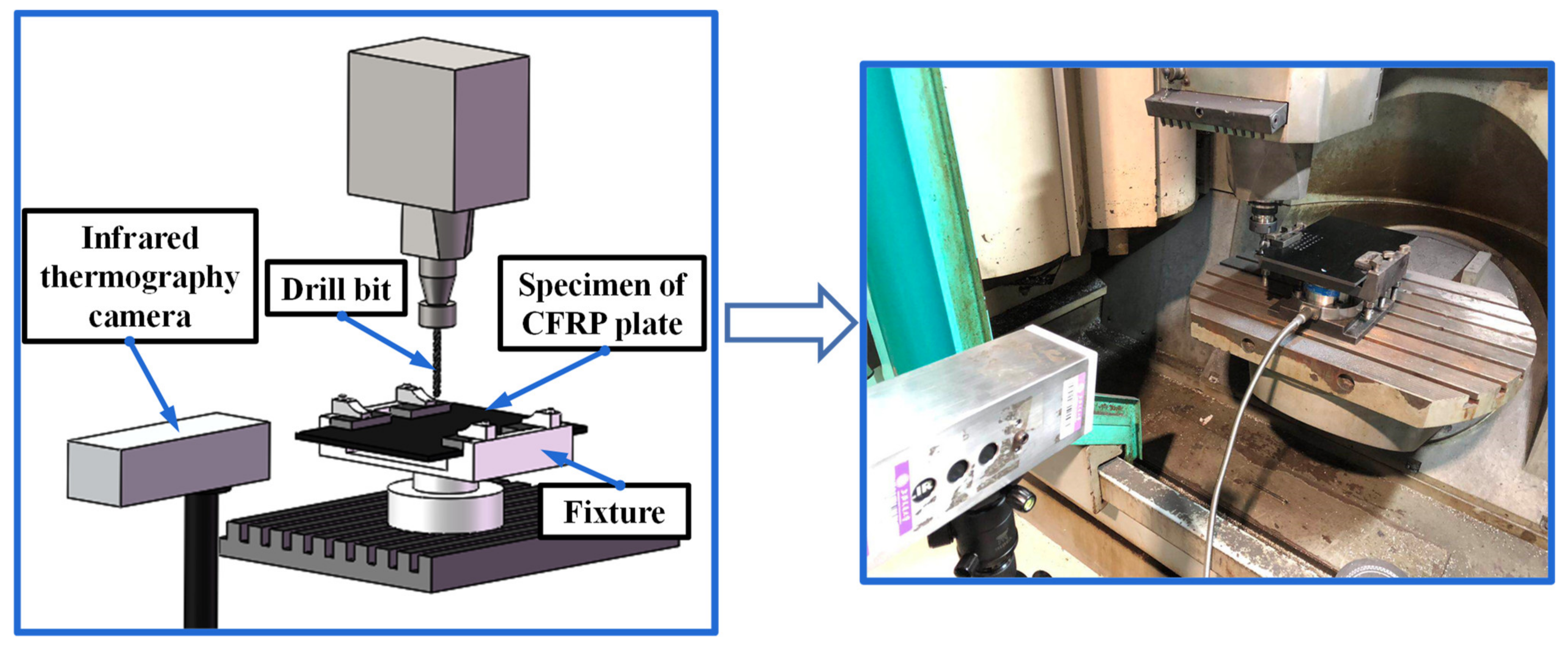
Figure 1. The experimental setup for the CFRP drilling.
Jcs 06 00045 g001
Figure 2. The morphologies of the used special drills.
Jcs 06 00045 g002
Figure 3. Thermal images of drilling temperature development when using candlestick drills (Vc = 120 m/min).
Jcs 06 00045 g003
Figure 4. Thermal images of drilling temperature development when using step drills (Vc = 120 m/min).
Jcs 06 00045 g004
Figure 5. Comparison of drilling temperature development between candlestick and step drills (Vc = 120 m/min and f = 0.06 mm/rev).
Jcs 06 00045 g005
Figure 6. Evolution of the maximum drilling temperatures in terms of the process parameters.
Jcs 06 00045 g006
Figure 7. CLSM image of a CFRP hole wall cut by the candlestick drill and its cross-sectional profiles (Vc = 120 m/min and f = 0.09 mm/rev).
Jcs 06 00045 g007
Figure 8. Topographies of a CFRP hole wall cut by the candlestick drill (Vc = 120 m/min and f = 0.09 mm/rev).
Jcs 06 00045 g008
Figure 9. CLSM image of a CFRP hole wall cut by the step drill and its cross-sectional profiles (Vc = 120 m/min and f = 0.09 mm/rev).
Jcs 06 00045 g009
Figure 10. Topographies of a CFRP hole wall cut by the step drill (Vc = 120 m/min and f = 0.09 mm/rev).
Jcs 06 00045 g010
Figure 11. The hole diameter in terms of different feed rates and drill bits (Vc = 40 m/min).
Jcs 06 00045 g011
Figure 12. The hole diameter in terms of different feed rates and drill bits (Vc = 80 m/min).
Jcs 06 00045 g012
Figure 13. The hole diameter in terms of different feed rates and drill bits (Vc = 120 m/min).
Jcs 06 00045 g013
Table 1. The composition of the used CFRP composite.
ReinforcementMatrix BaseFiber Volume FractionFiber Bundles
T700 carbon fibersFRD-YZR-03 epoxy60%7 µm, 12 K
Table 2. The mechanical properties of the used CFRP composite.
Tensile ModulusTensile StrengthPoisson’s Ratio, νFlexural ModulusFlexural StrengthShear StrengthGlass Transition Temperature
240 GPa4900 MPa0.30210 GPa1500 MPa125 MPa125~135 °C
Publisher’s Note: MDPI stays neutral with regard to jurisdictional claims in published maps and institutional affiliations.