1. Introduction
The most well-known failure criteria for modern composites are the maximum stress criterion and the maximum strain criterion. They are, in fact, so well-known that nobody can be bothered to trace back to where they were introduced in the first instance, although it is apparent that each stemmed from a conventional failure criterion for conventional isotropic materials established way before modern composites became available. They are being incorporated into modern engineering design tools, such as Abaqus [
1] and Ansys [
2], to name but a few. They remain popular in applications due to their simplicity, especially amongst designers in situations where a rough but quick estimate is required. This status is likely to remain so for a long time to come. Their other benefits include that they also offer a clear indication about the failure modes, and that they are applicable to genuinely orthotropic materials, rather than transversely isotropic materials alone. Critiques about them are often based on the fact that there is a lack of interactions amongst the stress or strain components, and hence the predictions made using them are not expected to be accurate, especially in problems where competing components of the stress or strain state are present. Apart from this, there do not seem to be any comprehensive appraisals especially focusing on their formulations, perhaps because they have been perceived as being too simple to be paid any attention to, as reviewed in [
3]. On the other hand, there have been attempts to adapt or modify them in order to make up for any specific shortfall in their performances. Without attempting to exhaust such examples, Zinoviev et al. [
4] topped up the maximum stress criterion with a certain allowance for property degradation, and Hart-Smith [
5] adapted the maximum strain criterion by truncating the failure envelope to the tension–tension and compression–compression ends. Interested readers can explore a vast volume of literature along such lines regarding these two popular composite failure criteria. In the background, a much wider range and more extensive studies are available in the literature; some of them have been included in the World Wide Failure Exercises (WWFE-I~III) [
6,
7,
8], of which references [
4,
5] were a part. Another popular criterion is the Tsai-Wu criterion, which has been recently rationalized by the author and his co-workers in [
9]. It will be employed in the case study, as will be presented in
Section 6 of this paper later.
It should be pointed out that the criteria of this category are meant to be for material failure. For applications to laminated structures, a criterion will have to be applied ply by ply, with a ply treated as a material. Intra-ply failure modes [
10,
11] can be predicted based on the stresses in the ply. However, such predicted failure modes should be understood as local modes of failure, or more conventionally referred to as the onset of the damage. Given the fact that laminated structures can normally sustain a substantial load beyond the onset of the damage, these failure criteria do not normally predict the final failure of the laminate concerned. When the fracture surface happens to be parallel to the surfaces of the ply, the failure predicted by these criteria could be employed to predict the onset of inter-ply damage. Equally true, laminates can usually sustain a significantly higher load level beyond this point.
The present paper is intended to examine the formulation of these two criteria in the context of transversely isotropic materials, by revealing crucial aspects which have been overlooked hitherto. It will be found that, being so popular and historical, they deserve a proper scrutiny and some clarifications, although none of this is meant to be over-sophisticated. The outcomes are twofold: the unification of these two criteria, and a rational, and hence improved, presentation of them.
3. The Conventional Maximum Strain Failure Criterion
Assume the strain state as expressed in the material’s principal axes as
. Denote the tensile and compressive failure strains along the fiber direction as
and
, those transverse to the fiber direction as
and
, respectively, and the shear failure strains along and transverse to the fibers as
and
. The conventional maximum strain criterion can be expressed as follows [
1,
2]. For the material to remain safe,
Whilst the maximum strain criterion inherits most features from the maximum stress criterion, it suffers from additional inconsistencies, which will be the subject of the next section.
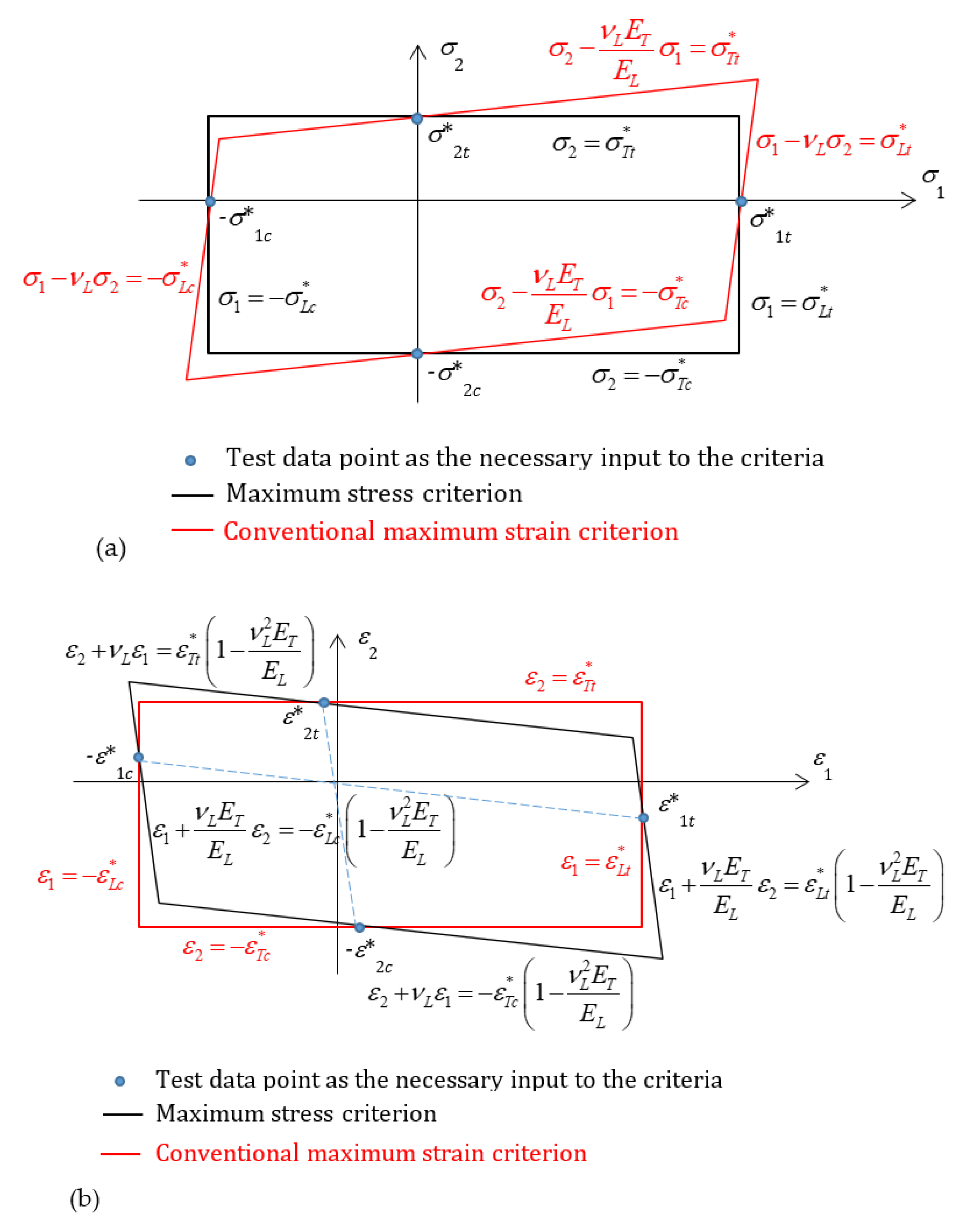
If one expresses the strains in terms of stresses using the generalized Hooke’s law, a degree of interactions would be present amongst the stress components in the failure criterion. It could be perceived that the maximum strain criterion outperforms the maximum stress criterion, since one of the critical shortcomings of the maximum stress criterion is the lack of interactions amongst stress components. However, this is only a perception, and not true. The same shortfall of interactions amongst strain components is present in the maximum strain criterion. If the maximum stress criterion is expressed in terms of strains, some interactions amongst strain components would also emerge. Such interactions have been illustrated clearly in
Figure 1a,b, respectively, which show the failure envelopes for a stress/strain state involving only two in-plane direct components. The failure envelope according to the maximum stress criterion is a rectangle if it is plotted in the stress plane where there is an obvious lack of interactions between stress components, i.e., failure in one direction, e.g., along fibers, is not affected by the presence of stress transverse to the fibers. The failure envelope according to the maximum strain criterion is shown as a parallelogram in the stress plane, where a degree of interactions between stress components are present, i.e., failure in one direction, e.g., along fibers, is affected to a degree by the presence of stress transverse to the fibers, as shown in
Figure 1a. The opposite is observed once the failure envelopes are plotted in the strain plane instead, as shown in
Figure 1b. The two criteria, as they are, are simply complementary, and none is superior to the other in this respect.
4. Unification between the Conventional Maximum Stress and Strain Failure Criteria
The maximum stress and strain criteria are identical in terms of their shear components, because any shear stress or strain is decoupled from other shear, as well as any direct, stress or strain, given the transverse isotropy of the material. In order to unify these two criteria, one only needs to do so for direct stresses and strains. The discussion to follow will be concentrated on the direct components of stresses and strains.
By comparing conditions (1)–(3) and (7)–(9) superficially, one might perceive that the maximum stress and strain criteria mirror one another, one being based on stresses and the other on strains, in a complementary manner. However, a closer examination reveals that the correspondences are biased. The strengths against direct stresses and failure strains against direct strains are both defined under corresponding uniaxial stress states, and measured, in that manner, as close to such a stress state as practically possible. An absolute complementary mirroring would require that all failure strains against direct strains be measured under corresponding uniaxial strain states. The practicality prohibits such failure strains from being experimentally measured. Instead, they are all defined under the same stress state as in the maximum stress criterion, thus spoiling the symmetry.
An important but hardly attended-to consideration is the Poisson effect of the material in the consideration of the maximum strain criterion. A simple observation is that, under a multiaxial stress state, a positive stress in a direction does not always correspond to a positive strain in the same direction. When the strength or the failure strain is reached when the material is loaded under a uniaxial stress state, strains are induced in the direction sideways to the loading direction due to the Poisson effect. These sideways strains are a natural manifestation of material deformation. If this tendency is free from any interference, as in the case of uniaxial stress states, these sideways strains should not make contributions to the sideways failure of the material, because they are not associated with any no-vanishing stresses. However, if this tendency is suppressed artificially, whilst the sideways strains vanish, additional stresses will have to be introduced to suppress such strains.
An anomaly can thus be revealed immediately if the maximum strain criterion is examined with the above considerations in mind. Consider a real composite (S2-glass/epoxy) whose effective properties are [
13]
where
and
are the Young’s moduli in the longitudinal and transverse directions, and
is the longitudinal Poisson’s ratio of the material. Given the Poisson effect, under uniaxial stress in the fiber direction, the strain ratio should be
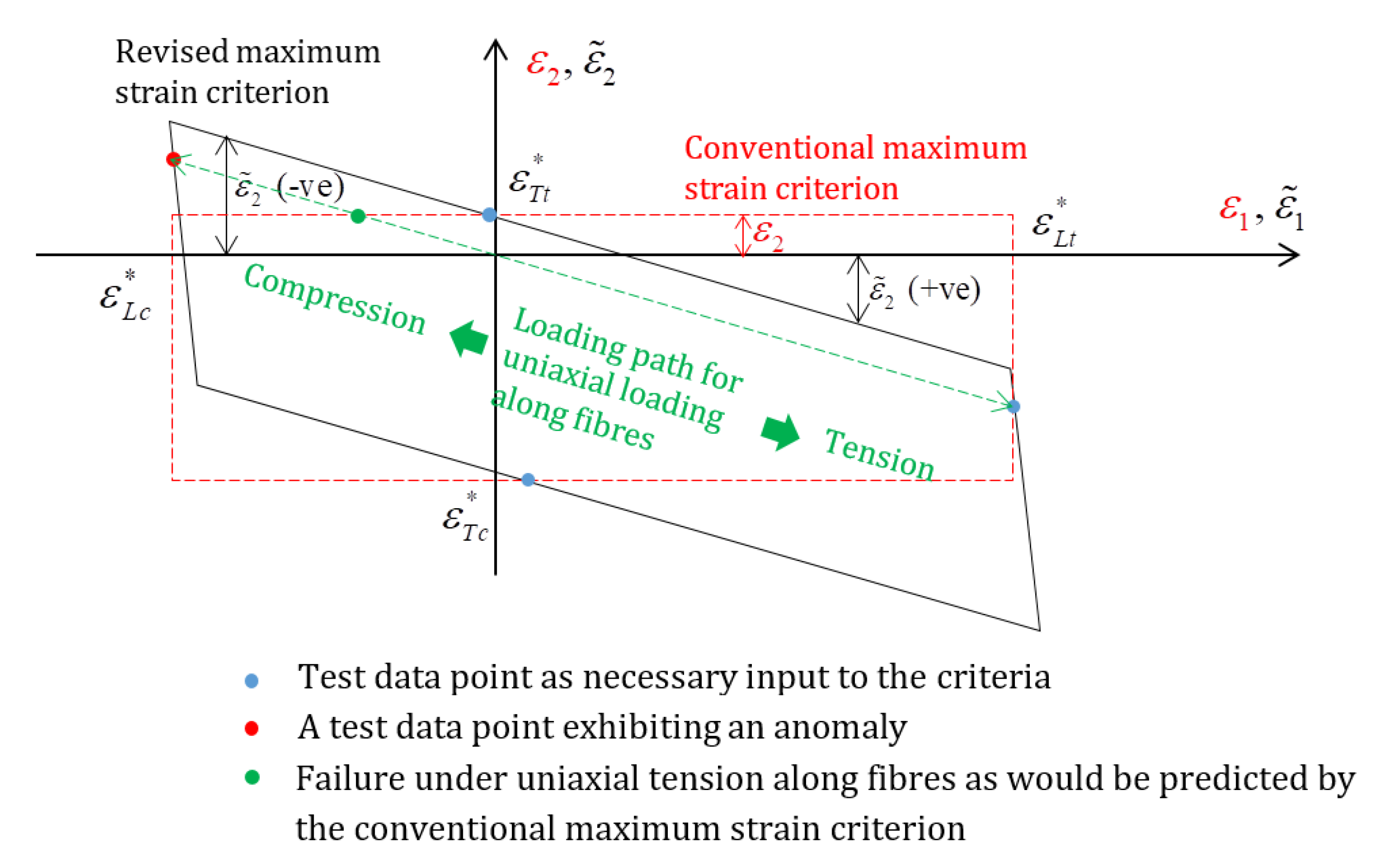
. In the physical deformation process leading to failure under uniaxial compression in the fiber direction, the longitudinal compressive failure strain of 2.21% should be accompanied by a positive transverse strain at 0.66%, which doubles the transverse tensile failure strain of 0.33%. When the failure envelope is plotted in the 1–2 plane of strains, as shown in
Figure 2, the data point for the longitudinal compressive failure strain (shown red) from the actual test is outside of the failure envelope, according to the conventional maximum strain criterion, by a substantial margin. Using the criterion for the loading case of uniaxial compression in the fiber direction, the failure would be predicted at half of the load level, i.e., 1.10%, and the failure would be in a transverse tensile mode, as indicated by the green blob on the loading path, as shown in
Figure 2. This neither makes sense nor reflects the experimental observations. In other words, the criterion is incapable of reproducing these particular input data correctly, and therefore fails to pass a ‘sanity check’. This is considered as a logical inconsistency in the conventional maximum strain criterion, and is therefore a much more significant problem than insufficient accuracy. It is the author’s view that for any theory, its accuracy is irrelevant before it achieves basic logical consistency. The unification to be presented later in this section is to eliminate this inconsistency as its first objective.
Another unreasonable aspect can be observed if the material is subjected to longitudinal tension whilst the transverse direction is suppressed from any strain. At
= 600 MPa, i.e., about a third of the strength, which is still far from any possibility of failure in the fiber direction, a transverse stress
= 66 MPa >
= 63 MPa will be generated. It is therefore unlikely that the material will survive any significant increase in loading in this respect. The stress in the fiber direction,
, on the other hand, could be easily doubled to 1200 MPa, which is still substantially below
= 1700 MPa, and there would not be any imminent danger of fiber-direction failure. However, by then,
would be twice its usual strength,
. The chance of keeping the material intact in its transverse direction is not great, although the strain in this direction has been kept at zero, and therefore according to the maximum strain criterion it would never fail in the transverse direction. The transverse stress induced by
in this case is merely to prevent the shrinkage which would otherwise take place due to the Poisson effect if the material had been loaded under a uniaxial stress state along the fibers. Under a uniaxial stress along the fibers, where the material is absolutely free from transverse constraints, one would not normally expect failure to take place in the transverse direction. In other words, free strain due to the Poisson effect does not contribute to the failure of the material, but any forces suppressing it do. Although the material in the example elaborated above does not exhibit any
apparent strain in the transverse direction, to suppress the deformation in the transverse direction, the material has been subjected to an
effective strain equal to the shrinkage, but in the opposite sense, as indicated in
Figure 2 by
. The terms apparent strain and effective strain will be defined later and more precisely in their subsequent uses.
The material referred to above show a little nonlinear behavior under transverse compression [
13]. None of the above cases involves this aspect. They were all well within the linear regime of the material, and material nonlinearity is not the reason for the anomalies. It is clear in both cases, as elaborated above, that the lack of rationality in the maximum strain criterion is due to the use of apparent strains to assess the failure, and a logical way forward would be based on the effective strains.
According to the generalized Hooke’s law, the strain in one of the principal directions, e.g.,
, consists of three parts:
is the strain in this direction due to the stress in this direction under a uniaxial stress state, and
and
, as the other parts, are the strains in this direction resulting from the Poisson effect due to the stresses in the other two principal directions, under respective uniaxial stress states. Thus, in general, one has
where
νij (
i,
j = 1, 2 and 3) are the Poisson’s ratios in the conventional sense for orthotropic materials in general, and
(
i = 1, 2 and 3) are the strains as obtained under the respective uniaxial stress states, referred to as
effective strains hereafter, whilst the conventional strains
(
i = 1, 2 and 3) are referred to as
apparent strains. For transversely isotropic materials, the above can be given as below, in more common notation of their effective elastic properties:
where
and
have been previously introduced and
is the material’s transverse Poisson’s ratio. With minimal manipulation with (A5)–(A8) as provided in
Appendix A, the effective strains can be expressed in terms of apparent strains, as follows for 3D cases and the plane stress conditions, respectively.
As argued earlier, it would be more meaningful to employ effective strains as measures in order to assess the failure of the material in the directions concerned, instead of the apparent strains, since the effective strains are in fact the adjusted values of strains after eliminating the distraction from the Poisson effect. It will therefore be more sensible to replace conditions (7)–(9) with the following:
The above argument applies in a straightforward manner if a plane stress condition is considered. The same plane stress problem for S2-glass/epoxy as cited above can be employed to illustrate the disparity between the conventional criterion and its revised form, as formulated above and also shown in
Figure 2, where the conventional criterion gives the failure envelope as a rectangle sketched in red dashed lines (not to scale), whilst the newly formulated one is shown as a parallelogram in black solid lines. The latter reminds one of the appearance of the failure envelope from the maximum stress criterion, but expressed in terms of strains on the same plane, as plotted in
Figure 1b.
In fact, if one accepts the argument and formulation above, he/she can then find that conditions (17)–(19) reproduce those in (1)–(3) identically under the condition of linear elasticity. The derivation will be provided in
Appendix A. This unifies the maximum strain criterion with the maximum stress criterion. The parallelogram in
Figure 2 is identical to the failure envelope from the maximum stress criterion, but plotted in the strain plane. The considerations underlying the unification are the facts that the failure strains for direct strains are obtained under uniaxial stress states, and that sideways strains due to the Poisson effect do not contribute to the failure in these directions. These considerations happen to be implied within the framework of the maximum stress criterion.
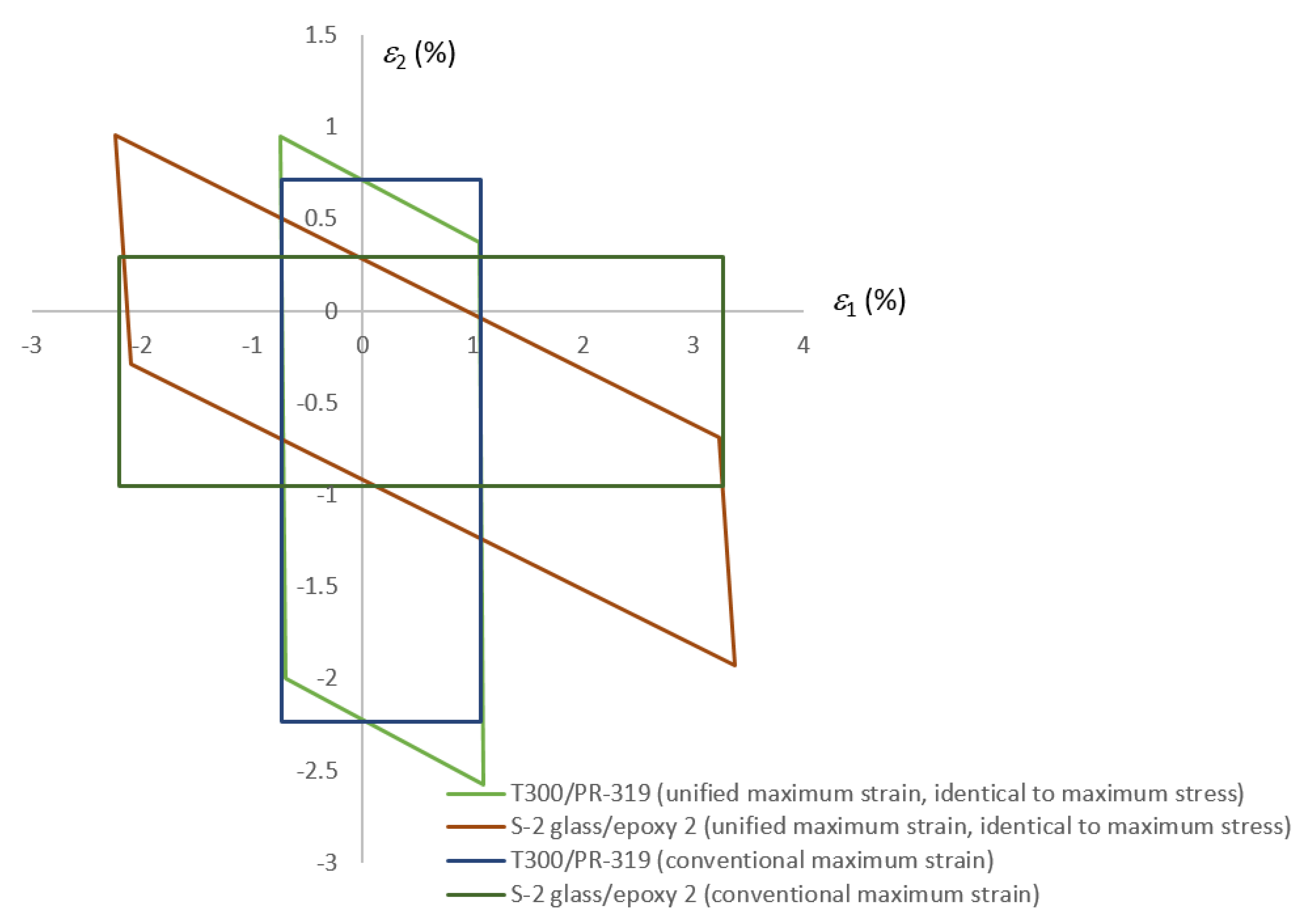
The plots of the failure envelopes for two known materials,
viz. those denoted as S-2 glass/epoxy2 and T300/PR319, as found in [
13], are produced in
Figure 3 to scale. It can be seen that not every composite exhibits the anomalies as described above, e.g., T330/PR-319, whereas the anomalies of S-2 glass/epoxy2 can now be quantified from
Figure 3 if one wishes.
The same considerations can be given to the strains due to the hygro-thermal effects, as well as residual thermal stresses, under the phenomenological framework, i.e., the transversely isotropic material is assumed to be homogenous. To express this explicitly, the strains in the material due to hydro-thermal effects do not contribute to the failure, although this, as well as the strains due to the Poisson effects, can be disputed on the basis of micromechanics, which is a different subject from the present discussion.
5. Further Rationalization
Having unified the maximum stress and strain criteria, one only needs to concentrate on one of them in order to further rationalize them. It is apparent that the former gives a more concise presentation, relatively.
A consistent failure criterion should observe the basic principle of objectivity, as in mechanics and physics [
12]. Given a stress state and the transverse isotropy of the material, the behavior of the material, such as failure, should be observed equally in all coordinate systems sharing the common axis 1. Any such coordinate systems are principal coordinate systems, and the principal coordinate system is not unique due to the transverse isotropy of the material. Because of this, the material’s principal axes in the plane transverse to the fibers have lost their representativeness, and the material does not have any preference in terms of failure modes in this respect. In the spirit of the maximum principal stress criterion for isotropic materials [
14], the failure transverse to fibers should be determined by the stresses in the transverse plane alone. A stress tensor (stress state) is a coordinate transformation invariant, although it may resolve into different components in different coordinate systems. The predicted failure based on the stress state should therefore not vary if one switches the coordinate system from one to another between different coordinate systems.
With the conventional maximum stress criterion, by choosing different coordinate systems, one can obtain infinite numbers of different predictions for transverse failure. Take a pure shear stress state in the transverse plane as an example. By rotating the coordinate system about axis 1, the transverse stresses will vary following the corresponding coordinate transformation rule. Without exhausting all intermediate positions, two characteristic presentations of the stress state are pure shear (in the original coordinate system) and equal biaxial tension and compression (in the coordinate system rotated 45°). For pure shear, condition (4) predicts the failure based on the transverse shear strength. Under equal biaxial tension and compression, the failure should be determined by conditions (2) and (3), one in tension and one in compression. Modern composites are usually brittle with regard to their failure modes in the transverse directions, and hence tensile strength is usually much lower than its compressive counterpart. As a result, the failure under equal biaxial tension and compression takes the transverse tensile fracture mode, and it is dictated by the transverse tensile strength of the material. Two distinct predictions of failure are obtained, leading to different load levels of failure in general only because of the selection of different coordinate system, unless the transverse shear strength is equal to that for transverse tension. This reveals the lack of objectivity in general in the conventional maximum stress criterion.
Another example can be shown in terms of longitudinal shear stresses. Take the same S2-glass/epoxy composite as an example. Its longitudinal shear strength is 72 MPa. Assume that the material is under the following stress state:
According to conditions (1)–(6), none of the ratios there will exceed 1, and therefore the material should be safe according to the conventional maximum stress criterion. However, if one rotates the coordinate system 1-2-3 about axis 1 by 53.1° following the right-hand rule, then in the new coordinate system 1-2′-3′, one has
If the new coordinate system has been selected, condition (6) will not be satisfied. In other words, failure is predicted now. Between the two predictions, the difference is again only a change in coordinate system, and the two coordinate systems involved are both principal systems and are meant to be equivalent in terms of describing the behavior of the material. The lack of objectivity is obvious. It is also clear that the lack of objectivity is primarily associated with problems involving out-of-plane stresses. The in-plane behavior of the material under plane stress conditions is not affected.
It ought to be noted that in the presence of a nonlinear stress–strain relationship, which is common between the longitudinal shear stress and strain, the unification as presented in the previous section is no longer valid in general. Different predictions are expected using the maximum stress and strain criteria.
The lack of objectivity as revealed above can be corrected if the maximum stress criterion is re-presented as follows, employing the stress along the fiber direction as before, but with the maximum and minimum direct stresses transverse to the fibers, the maximum transverse shear stress and the maximum longitudinal shear stress, which are all invariants amongst different principal coordinate systems.
where
are the maximum and minimum direct stresses transverse to the fibers,
is the maximum transverse shear stress, and
is the maximum longitudinal shear stress.
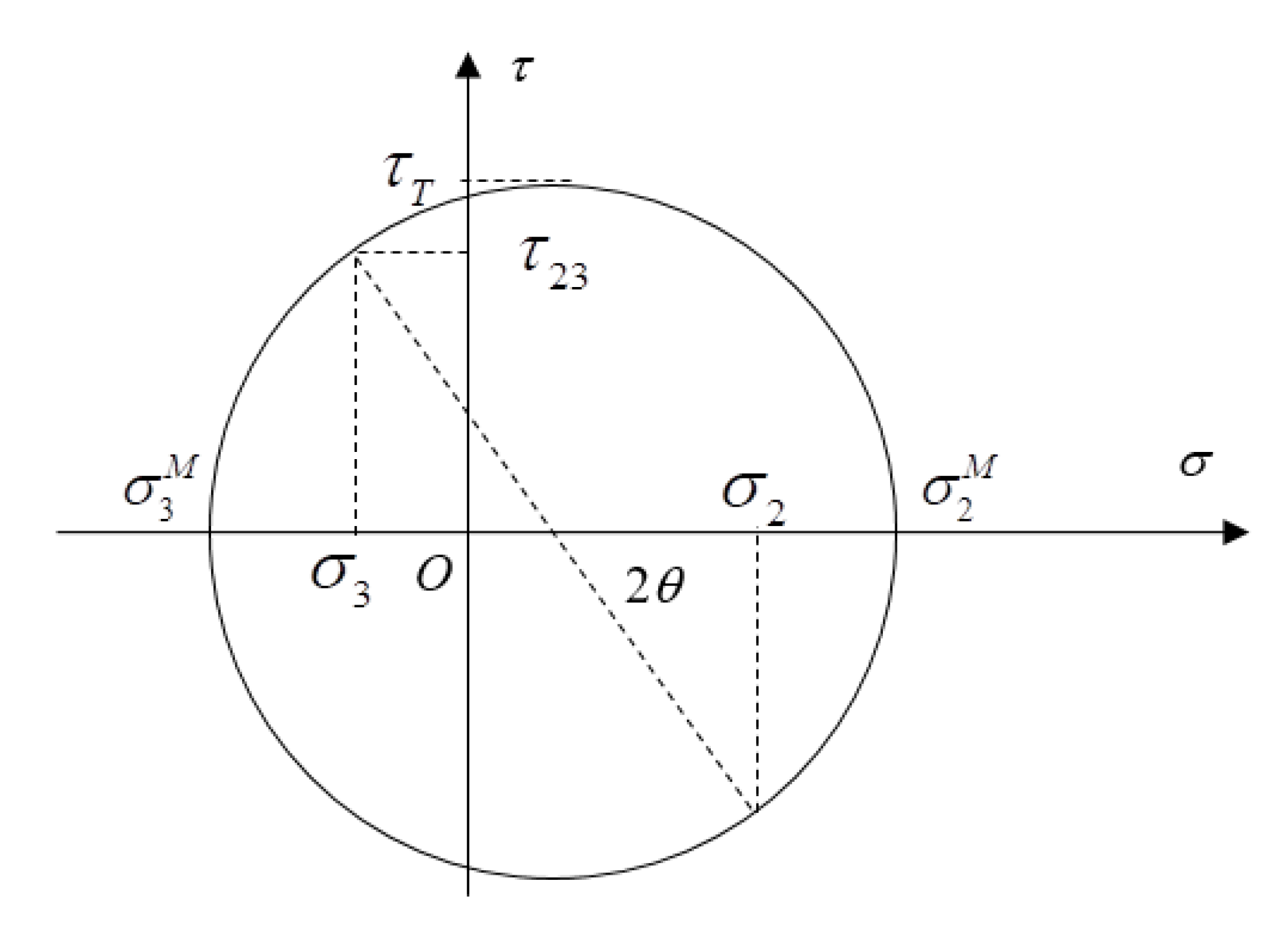
The maximum and minimum transverse stresses
and
, and the maximum transverse shear stress
, can be easily determined from
and
by employing a Mohr’s circle, as illustrated in
Figure 4. It should be noted that
and
are not principal stresses in general, because on their action planes the longitudinal shear stress is usually not zero.
In terms of failure modes, if the failure is due to the longitudinal tension, fracture is expected on a plane transverse to the fibers, i.e., the action plane of the tensile stress in the fiber direction. When it is due to longitudinal compression, the fracture usually takes the form of a fiber kink band on a plane at an angle to the fiber direction, which is usually not the action plane of the compressive stress in the fiber direction.
When transverse tension dictates the failure, a fracture is usually observed on a plane parallel to the fibers, as the action plane of the tensile transverse stress, which is at an angle
θ from axis 2, where
Compression-dominated transverse fracturing is usually expected on a plane parallel to the fibers, but at about 45° from the direction of compressive stress, and hence
from axis 2. Again, it is not the action plane of the responsible stress, as the failure is primarily due to the transverse shear stress on the fracture plane.
If the failure is caused by transverse shear, the fracture is usually expected on a plane parallel to the fibers but at about 45° from the action plane of the shear stress, and hence from axis 2, in the direction of the maximum tensile stress transverse to the fibers.
It can be seen that the three different modes of failure in the transverse direction are somehow related. The inter-relationship amongst them carries the following implications on the transverse strengths of the material, tensile compressive and shear. Since they are usually measured using different testing methods with specimens of different dimensions, in particular thicknesses, which might require that the specimens be processed through different curing cycles, it is unlikely that they are obtained in a perfectly consistent manner. It is not uncommon that some of these properties have been ‘borrowed’ from similar materials. Without undermining existing data from the literature, some basic ‘sanity checks’ should be conducted before any set of them is employed in serious applications. First, the compressive strength should be comparable with twice of the shear strength, unless the fracture is greatly different from what was described above. Some variability is acceptable due to the two competing arguments: (1) the compression on the fracture surface helps the resistance to failure due to shear, and (2) the fracture is likely to take place at an angle slightly different from 45° as a more vulnerable aspect of the material is stressed. Secondly, the shear strength should not be greatly different from the tensile strength, unless the fracture is characteristically different from what was described above under transverse shear. The transverse strengths of a range of typical composites, such as those involved in WWFE-I~III [
6,
7,
8] and also employed in [
9], have been listed in
Table 1, where the ratios of the relevant strengths have been included. Whilst
, some of them appear significantly above 2, and many of them fluctuate reasonably above 2. Ratios of
vary around 1, and some of them with a significant margin. For serious applications, users are encouraged to double check their strengths values and justify them against the failure modes observed.
Failure due to the longitudinal shear stress takes place on the action plane of the maximum longitudinal shear stress parallel to the fibers, which is at the angle
β from axis 2, where
Under a plane stress condition, those terms associated with subscript 3 disappear, and it returns back to its conventional form under the condition with the criterion given by (20), (21) and (24), where and are identical to and , respectively. The lack of objectivity pertains only to the 3D form of the conventional maximum stress criterion.
If one prefers to have the failure criterion expressed in terms of strains, the unified and rationalized criterion, as above, can be presented as follows, whilst the discussion about the failure modes remains the same as above.
where
from the Mohr’s circle for strains in a similar way to that as shown in
Figure 4,
are the maximum and minimum direct strains transverse to the fibers,
is the maximum transverse shear strain, and
is the maximum longitudinal shear strain.
The transverse strains
and
can be easily determined from
and
. The angles
θ and
β remain the same as before in the rationalized maximum stress criterion, but can be expressed in terms of strains, as follows.
Under a plane stress condition, the criteria are expressed in (30), (31) and (34), with the effective strains defined as
whilst
is the same as
.


