Article

Measuring the Electrical and Photonic Properties of Cobalt Oxide-Containing Composite Carbon Fibers

1
Department of Mechanical Engineering, California State Polytechnic University Pomona, 3801 W Temple Avenue, Pomona, CA 91768, USA
2
Department of Chemical and Biomolecular Engineering, University of California Los Angeles, 405 Hilgard Ave, Los Angeles, CA 90095, USA
*
Author to whom correspondence should be addressed.
J. Compos. Sci. 2020, 4(4), 156; https://doi.org/10.3390/jcs4040156
Submission received: 6 September 2020 / Revised: 19 October 2020 / Accepted: 20 October 2020 / Published: 22 October 2020
(This article belongs to the Special Issue Composite Carbon Fibers)

Abstract

:
In this work, cobalt acetate was incorporated into polyacrylonitrile (PAN) polymer through electrospinning as the cobalt oxide source. After oxidization and pyrolysis, a PAN-derived composite carbon fiber containing cobalt oxide was obtained. Measuring the electrical and photonic properties of the composite fiber under visible light irradiation was performed to evaluate the photoelectric behavior of the composite fiber. The p-type semiconducting behavior of the composite fiber was confirmed by measuring the open circuit voltage of a photochemical fuel cell consisting of the photosensitive electrode made from the composite fiber. The application of the composite fiber for glucose sensing was demonstrated.

1. Introduction

Oxide-containing composite fibers have been widely researched for various applications including photocatalysis [1,2,3,4,5,6,7,8,9,10,11,12,13,14,15,16,17,18], antibacterial action [19], light emitting [20,21,22,23,24,25,26,27], optical and dielectric constant tuning [28], photovoltaics [29,30], sensing [31,32,33] and energy storage [34]. Among various oxides, the n-type ones including ZnO [3,4,7,26,32], TiO2 [2,6,9,11,12,16,29] and Fe2O3 [15] have been extensively investigated. On the contrary, p-type oxides are much less studied for photonic applications. Copper oxide as one of the p-type semiconducting oxide was examined for high-efficiency photocatalytic degradation of organic dyes and phenolic pollutants [5].
As a p-type semiconductor, cobalt oxide has caught attention due to its multiple valence values and easy to process. In Reference [35], a spray pyrolysis technique was used to make nanostructured Co3O4; the cobalt oxide (Co3O4) nanofibers were deposited onto a glass substrate by spraying cobalt acetate Co(CH3COO)2∙4H2O precursor solution. Field emission scanning electron microscopic (FESEM) analysis revealed uniformly grown Co3O4 nanofibers aligned regularly on the substrate. Patel et al. [36] measured the thermal electric response of the co-electrospun cobalt oxide particle containing carbon nanofiber heated by a hot air gun. The time dependent response to the thermal wave generated by the hot air from the heating gun was shown. The hot air gun was pointed at the specimen intermittently. Each time, a strong electrical potential peak was generated indicating the thermoelectric response from the cobalt oxide containing carbon composite fiber. Xu et al. [37] also presented the work on making Co–Ni oxide compound-containing nanofibers with the core-shell structure for high performance supercapacitors.
The objective of this work was to convert cobalt acetate incorporated in polyacrylonitrile (PAN) to cobalt oxide to interrogate the photoelectrical behavior of the composite carbon fiber. First, co-electrospinning the polymer and the cobalt salt mixture was performed to obtain the precursor for the composite fiber. Then oxidization and pyrolysis of the precursor was carried out to generate a PAN-derived composite carbon fiber containing cobalt oxide. Measuring the electrical and photonic properties of the composite fiber under visible light irradiation was conducted to show the photoelectric behavior of the composite fiber. The p-type semiconducting behavior of the composite fiber was revealed through measuring the open circuit voltage of a photochemical fuel cell consisting of the photosensitive electrode made from the composite carbon fiber. Finally, the application of the composite fiber for glucose sensing from biomass was discussed. The innovative part of this work lies in researching new composite fiber materials for flexible sensing component fabrication because the carbon fiber is highly compliant. In addition to that, carbon fiber based sensors have the advantage of stable in ambient environment and under typical service conditions.

2. Materials and Experimental

2.1. Materials and Instruments

A stainless steel injection needle, purchased from McMaster-Carr, Santa Fe Springs, CA, USA, was used as the spinneret for the electrospinning. The needle has a gage size of 20 with an outside tube diameter of 0.9016 mm. Polyacrylonitrile (PAN) polymer with a molecular weight of 150,000 Da was obtained from Scientific Polymer Products, Inc., Ontario, NY, USA. Other chemicals including dimethylformamide (DMF), cobalt (II) acetate tetrahydrate (all in the ACS purity) were ordered from Alfa Aesar, Ward Hills, MA, USA. Hydrogen gas was purchased from AirGas, Pomona, CA, USA. DMF was used as the solvent for making the PAN polymer solution and the cobalt acetate solution. A high voltage direct current power source was manufactured by Spellman, Inc. Hauppauge, NY, USA. A Fusion 200 precision syringe pump made by Chemyx, Inc., Stafford, TX, USA was used to inject the polymer cobalt salt solution during electrospinning. A model OTF-1200X-S-NT-LD compact split tube furnace with single heating zone and a programmable controller, made by MTI Corp in Richmond, CA, USA, was used for oxidization and pyrolysis of the fiber specimens. A model CHI-440C electrochemical workstation, made by CH Instrument in Austin, TX, USA, was used to test the photoelectric property of the composite fiber electrode.

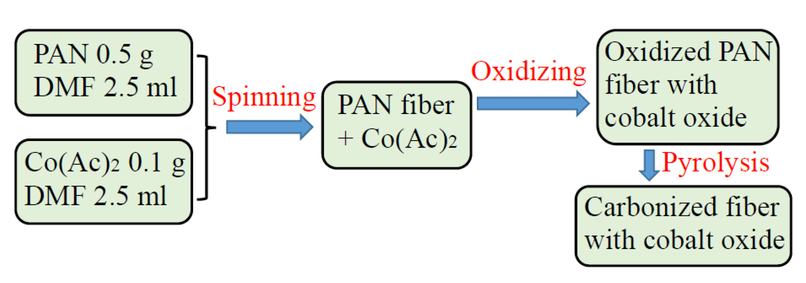
2.2. FiberPrrocessing

Two solutions (I and II) were made for the fiber electrospinning. Solution I stands for the PAN polymer in DMF. Solution II refers to the cobalt acetate in DMF. Solution I was made by dissolving 0.5 g PAN powder in 2.5 mL of DMF in a 25 mL beaker under vigorous stirring for 30 min at 50 °C. Solution II was obtained by adding 0.1 g cobalt acetate into 2.5 mL DMF. Then Solution II was poured into Solution I to form a uniform mixture for electrospinning. During the electrospinning, the injection rate of the syringe pump was kept as 0.01 mL/min. The power supply was turned on and set to 12 kV so that the electric field intensity was kept at 1.0 kV/cm. The fiber was deposited on a soft tissue paper which was rolled on a rotating metallic can. After air-dried, the fiber was cut into small pieces and oxidized in air for 2 h. The oxidation was conducted at 250 °C in the compact tube furnace. Finally, pyrolysis of the oxidized fiber at 500 °C was performed in the same split tube furnace under hydrogen protection. The pyrolysis time is 2 h. The electrospinning and heat treatment processes were schematically illustrated in Figure 1.

2.3. Characterization

A scanning electron microscope (SEM model: JEOL JSM-6010PLUS/LA) with an Oxford Instruments energy dispersive X-ray spectroscopy attachment was used to examine the microstructure and analyze the composition of the prepared composite fiber. A SONY DSC-W100 cyber-shot camera was used to take photos of the PAN fiber before the heat treatment. Representative pictures were used to show the global view of the fiber specimens. The CHI-440C electrochemical workstation was used to measure the open circuit voltages of specimens with and without visible light excitation. The electrochemical cell for the measurement consists of three electrodes: the composite fiber working electrode (W), the platinum counter electrode (C) and the Ag/AgCl reference electrode (R) as schematically shown in Figure 2. The composite carbon fiber samples were wrapped up with aluminum foil strips at the two ends. Since the aluminum foil is highly conductive, the metal strips served as the conducting paths. Alligator clips were used to clamp the two ends of each specimen. During the test, the data requisition rate was set as 10 data/s.

3. Results and Discussion

3.1. Morphology and Composition

The photos of two pieces of cobalt (II) acetate containing PAN fiber mats made by electrospinning are shown in Figure 3a. From the two photos, it can be seen that the red colored fibers were attached to the white tissue paper substrate. The red color of the fiber mat indicates the existence of cobalt (II) salt in the PAN fiber. After oxidation and pyrolysis, the composite carbon fiber was sputtering coated with gold for scanning electron microscopic (SEM) analysis. The SEM image presented in Figure 3b reveals randomly oriented fibers. Bead formation was not observed. Such a morphological feature is associated with the uniform distribution of the cobalt oxide in the carbon fibers. The chemical compositions of the fiber was analyzed by energy dispersive X-ray diffraction spectroscopy (EDS). Mapping of the selected areas was performed to generate the elemental information. The qualitative result for this fiber is shown in Figure 3c. It can be seen from Figure 3c that C, O, Au, and Co are the major elements in the fiber. Since gold (Au) signal is from the sputtered coating, it should not be counted as the element from the fiber. The characteristic peaks can be listed as follows: For cobalt, the Kα peak is located at 6.93 keV. It is also found that the Lα (0.78 keV) peak can be seen from the spectrum shown. For oxygen, the Kα peak at 0.53 keV is shown. For carbon the Kα peak is located at 0.28 keV.

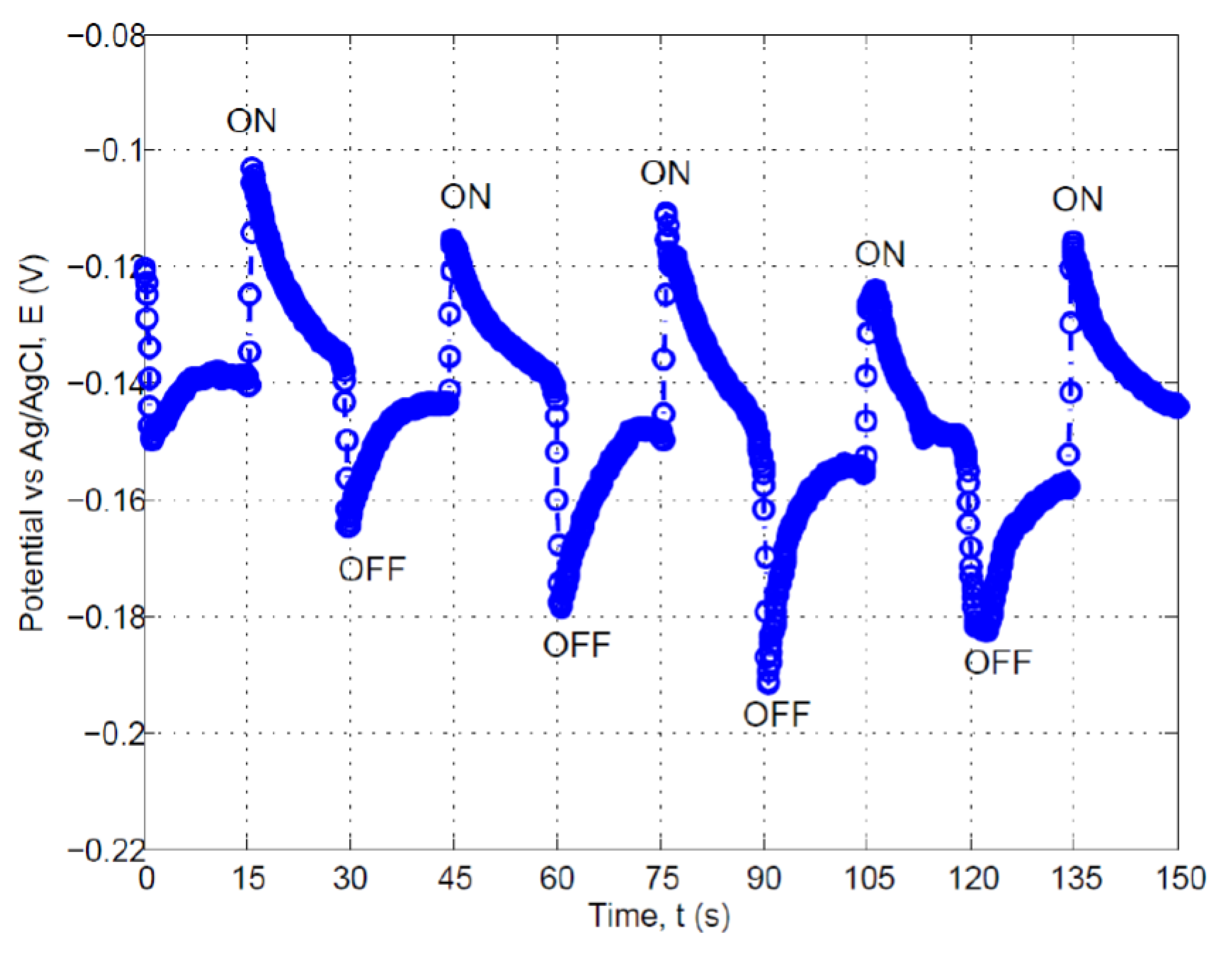
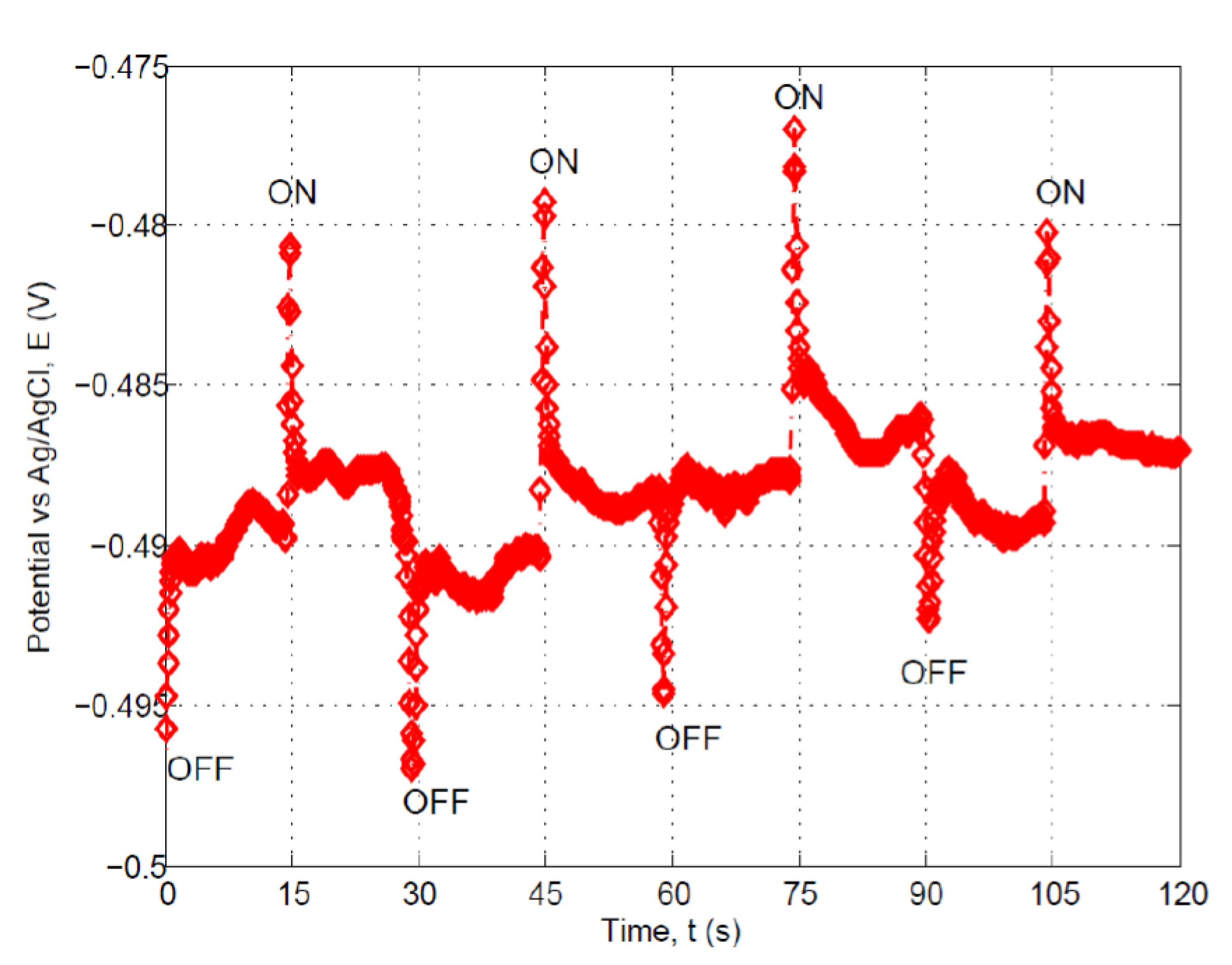
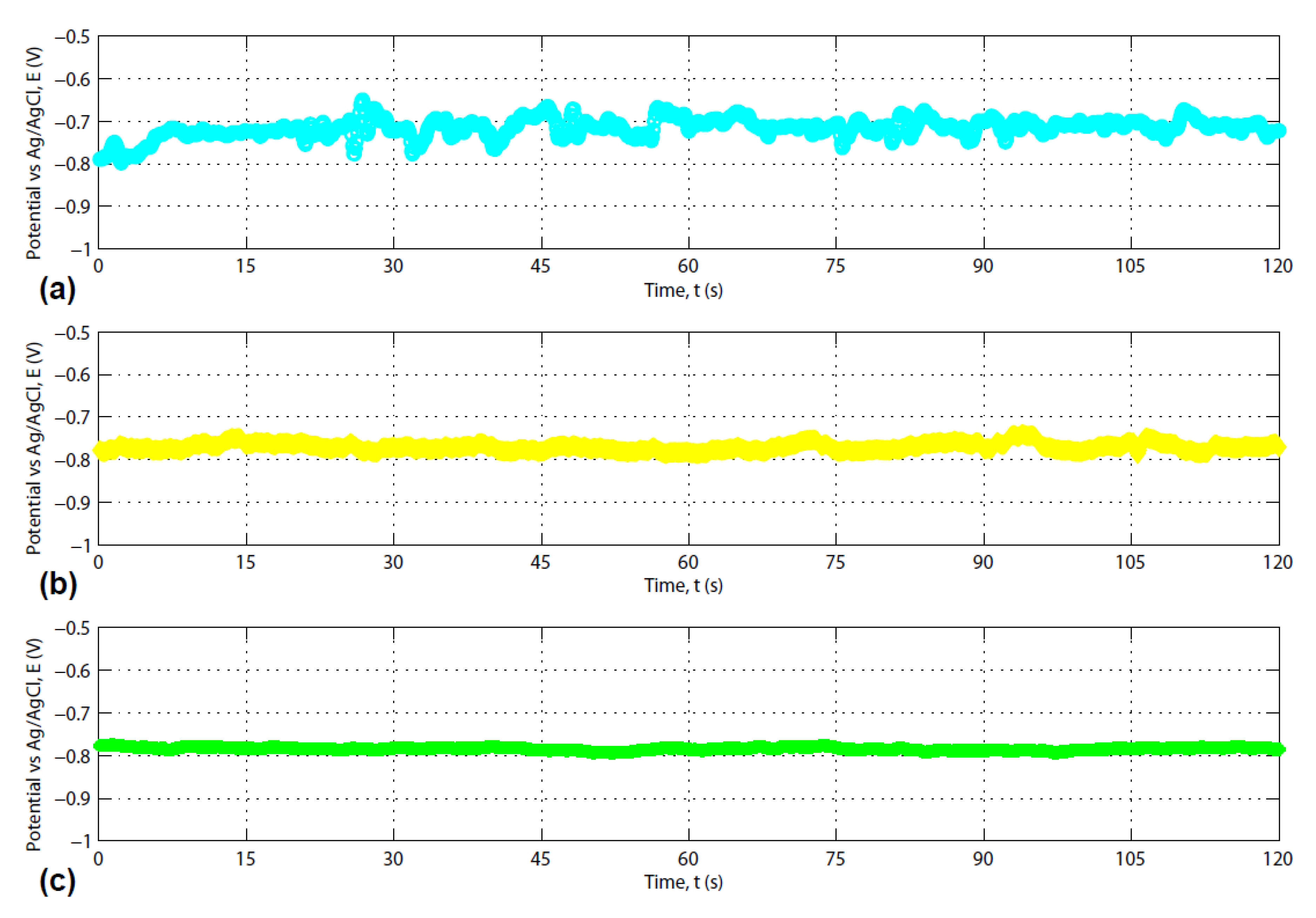
3.2. Photosensitivity of the Composite Carbon Fiber

The photoelectric behavior of the composite carbon fiber was evaluated using various solutions including sodium chloride, sugar (glucose), isopropyl, raspberry juice and orange juice. As illustrated in Figure 4, the photoelectric response of the fiber electrode in a 5.0 wt.% sodium chloride aqueous solution demonstrated the p-type semiconducting behavior. The voltage data were recorded when the sample was exposed to sunlight followed by being blocked with a black screen. The first cycle is 15 s, corresponding to the visible light just being blocked (“OFF” state). Then the sunlight-blocking screen was removed and the illumination lasted 15 s in the “ON” state and so forth. It was clearly shown by Figure 4 that the difference between the voltage peak and valley of 0.05~0.10 V was developed when the light illumination was switched from the “OFF” to the “ON” state. The positive voltage shift at the instant sunlight illumination validated that the composite carbon fiber showed a general p-type behavior. The possible electrochemical reactions are proposed as follows.
Co3O4 + hν → Co3O4 + h+ + e
NaCl → Na+ + Cl
H2O + Cl + h+ → HClO + H+
O2 + e + 2 H2O → 4 HO
HO + H+ → H2O
To simulate the charge and discharge behavior of the photoelectric responses of the electrode/electrolyte system, a circuit consisting of a resistor (R) and a capacitor (C) with the series connection [38] was used to establish the electrode/electrolyte interface model. When the visible light is ON, an immediate jump in the potential as shown in Figure 4 allows the capacitor to be fully charged. The mobility of the hole-electron pairs caused the decay in the potential as can be described by:
E ( t ) = E p e t R C ,
where E(t) is the time dependent potential; Ep is the peak potential (−0.12~−0.10 V for different peaks as shown in Figure 4), R is the resistance of the equivalent circuit; C is the capacitance of the electrode/electrolyte double layer. The values of R and C can be either determined experimentally by impedance measurement or by numerical computation from the measured E(t) data. The value of the resistance, R, should reflect the kinetic behavior of the photochemical reactions as delineated in Equations (1)–(5). While the product of the RC defines the reciprocal of the time constant for the electron-hole charge pair generation or annihilation depending on charging or discharging of the electrode/electrolyte system.
When the visible light is OFF, a sharp drop of the potential as shown in Figure 4 allows the capacitor to be fully discharged. The recombination of the hole-electron pairs led to the recovery of the potential to the equilibrium value. The recovery in the potential can be expressed as:
E ( t ) = E o ( 1 e t R C ) ,
where Eo is the equilibrium potential (−0.15~−0.14 V as shown in Figure 4).
Figure 5 reveals the trend of voltage variation with time for the composite carbon fiber specimen in a 5.0 wt.% sugar solution with and without visible light illumination. When the sunlight was ON, the voltage generated by the specimen showed a 10 mV jump. When the light is OFF, the voltage reduced by about 10 mV. As compared with the trend shown in Figure 4, Figure 5 showed a sharp increase in the electrochemical potential when the fiber specimen was excited by photon energy. Such a rapid responding behavior is good for building highly sensitive sensors for monitoring the existence of sugar. But the potential recovered very rapidly to the equilibrium around −0.487 V. This is because the sugar is a “hole-scavenger” as shown by the reaction formula of (8). The immediate recovery of the potential as shown in Figure 5 indicates that the hole-consumption is very fast. Therefore the decomposition of sugar follows a fast kinetics of reaction as shown by Equation (8).
6 H2O + C6H12O6 + 24 h+ → 6 CO2 + 24 H+
In Figure 6, the voltage data for raspberry juice, orange juice and isopropyl (all at 5.0 wt.%) do not show any significant sensitivity to the ON and OFF of the visible light as the three curves are almost parallel to the time axis. This indicates that the hole-electron pair generation and transport in the carbon fiber are at almost the same rate. However, the differences in the values of equilibrium potential vs. Ag/AgCl were found. For the composite fiber electrode in raspberry juice, the electrochemical potential was −0.7160 V. The equilibrium potential for the electrode in orange juice was −0.7704 V. For 5.0 wt.% isopropyl, this value was found at −0.7846 V. Orange juice and raspberry juice belong to biomass. Earlier studies on biomass energy harvesting under the photocatalysis of a titanium oxide nanotube electrode under ultraviolet (UV) light excitation were shown in References [39,40]. A switching behavior with the UV in ON and OFF states was observed [39,40], which is different from the behavior as shown in Figure 6.
To examine the possible concentration effect on the equilibrium potential, the composite fiber electrode was inserted into isopropyl aqueous solutions with various concentrations of 5.0%, 10.0%, 15.0%, 20.0%, 25.0%, 35.0% and 70.0% (all in weight per cent). The time dependent potential drift was plotted for each concentration case in Figure 7 except for the 5.0% one because the results were shown in Figure 6 already. From the plots shown in Figure 7, no sensitivity to the ON and OFF of the visible light was observed for the composite fiber electrode in various isopropyl solutions within a wide range of concentrations. In addition, the measured equilibrium potential values based on the mean of the potentials were listed in Table 1. With the increasing in the concentration of isopropyl in water, a slightly increasing in the equilibrium potential was found.
The unique result revealed in this figure indicates the feasibility of energy conversion from such a substance derived from sustainable biomass source through photocatalytic reactions at the cobalt oxide containing carbonized composite fibers. The open circuit voltage can be sustained even at a relatively low concentration of isopropyl. This is meaningful because high fuel concentration always imposes an issue of safety in storage. There are a lot of tasks to be done. For example, the microstructure examination could be performed using better tools as mentioned in Reference [41] for characterization of nanocomposites. The field emission scanning electron microscopy (FESEM) analysis at higher magnification of the fiber would be useful to show the cobalt acetate-derived particles. Other advanced measurement techniques such as X-ray photoelectron spectroscopy (XPS) which is based on the photoelectric effect can help identify the elements existing within the fiber or covering its surface. The chemical state, the overall electronic structure and the density of the electronic states in the fiber material could be determined as well. Such tasks are included in our future work.

4. Conclusions

Cobalt oxide can be incorporated into the partially carbonized composite fiber via electrospinning followed by pyrolysis. The scanning electron microscopic analysis reveals the existence of major elements: C, Co and O. The cobalt oxide containing carbon fiber demonstrates p-type behavior under the visible light excitation. Positive potential shift has been found associated with the positively-charged hole (h+) formation in the photosensitive electrode made by the composite fiber. The high sensitivity of the composite fiber to visible light allows detecting sugar in aqueous solutions. Photocatalysis behavior of the electrode in various biomass solutions including raspberry juice and orange juice. The photosensitive activity in isopropyl solution is also confirmed through the open circuit potential measurement. With the increase of isopropyl concentration in water, the equilibrium potential of the electrode shifts to the more positive values.

Author Contributions

Conceptualization, Y.X.G. and J.B.G.; methodology, Y.X.G.; software, J.B.G.; validation, Y.X.G. and J.B.G.; formal analysis, Y.X.G.; investigation, J.B.G.; resources, Y.X.G.; data curation, J.B.G.; writing—original draft preparation, Y.X.G.; writing—review and editing, J.B.G.; visualization, J.B.G.; supervision, Y.X.G.; project administration, Y.X.G.; funding acquisition, Y.X.G. Both authors have read and agreed to the published version of the manuscript.

Funding

This research received no external funding. The SEM images were made possible through the NSF MRI grant DMR-1429674. The APC was funded in part by MDPI.

Acknowledgments

Anan Hamdan is appreciated for assisting the SEM imaging.

Conflicts of Interest

The authors declare no conflict of interest.

References

  1. Ma, Y.; Lv, P.; Duan, F.; Sheng, J.L.; Lu, S.L.; Zhu, H.; Du, M.L.; Chen, M.Q. Direct Z-scheme Bi2S3/BiFeO3 heterojunction nanofibers with enhanced photocatalytic activity. J. Alloys Compd. 2020, 834, 155158. [Google Scholar] [CrossRef]
  2. Nasir, M.S.; Yang, G.R.; Ayub, I.; Wang, S.L.; Yan, W. In situ decoration of g-C3N4 quantum dots on 1D branched TiO2 loaded with plasmonic Au nanoparticles and improved the photocatalytic hydrogen evolution activity. Appl. Surf. Sci. 2020, 519, 146208. [Google Scholar] [CrossRef]
  3. Gadisa, B.T.; Kassahun, S.K.; Appiah-Ntiamoah, R.; Kim, H. Tuning the charge carrier density and exciton pair separation in electrospun 1D ZnO-C composite nanofibers and its effect on photodegradation of emerging contaminants. J. Colloid Interface Sci. 2020, 570, 251–263. [Google Scholar] [CrossRef] [PubMed]
  4. El-Fawal, E.M.; Younis, S.A.; Moustafa, Y.M.; Serp, P. Preparation of solar-enhanced AlZnO@carbon nano-substrates for remediation of textile wastewaters. J. Environ. Sci. 2020, 92, 52–68. [Google Scholar] [CrossRef] [PubMed]
  5. Cinar, B.; Kerimoglu, I.; Tonbul, B.; Demirbuken, A.; Dursun, S.; Kaya, I.C.; Kalem, V.; Akyildiz, H. Hydrothermal/electrospinning synthesis of CuO plate-like particles/TiO2 fibers heterostructures for high-efficiency photocatalytic degradation of organic dyes and phenolic pollutants. Mater. Sci. Semiconduc. Proc. 2020, 109, 104919. [Google Scholar] [CrossRef]
  6. Zendehzaban, M.; Ashjari, M.; Sharifnia, S. Preparation of floatable TiO2/poly(vinyl alcohol)-alginate composite for the photodegradation of ammonia wastewater. Int. J. Energy Res. 2020, 44, 2150–2163. [Google Scholar] [CrossRef]
  7. Baylan, E.; Yildirim, O.A. Highly efficient photocatalytic activity of stable manganese-doped zinc oxide (Mn:ZnO) nanofibers via electrospinning method. Mater. Sci. Semicond. Proc. 2019, 103, 104621. [Google Scholar] [CrossRef]
  8. Xiao, Y.; He, Z.Q.; Wang, R.S.; Tao, X.Q.; Li, B.X. Synthesis of WO3 nanofibers decorated with BiOCl nanosheets for photocatalytic degradation of organic pollutants under visible light. Colloids Surf. A Physicochem. Eng. Asp. 2019, 580, 123752. [Google Scholar] [CrossRef]
  9. Li, Y.J.; Cao, T.P.; Zhao, Y.H.; Sun, D.W.; Wang, X. Preparation of Bi@Bi2Sn2O7/TiO2 plasmonic composite fibers with enhanced photocatalytic hydrogen generation activity. Chin. J. Inorg. Chem. 2019, 35, 1371–1378. [Google Scholar] [CrossRef]
  10. Ramos, P.G.; Flores, E.; Luyo, C.; Sanchez, L.A.; Rodriguez, J. Fabrication of ZnO-RGO nanorods by electrospinning assisted hydrothermal method with enhanced photocatalytic activity. Mater. Today Commun. 2019, 19, 407–412. [Google Scholar] [CrossRef]
  11. Wang, Y.F.; Zhang, M.; Li, J.; Yang, H.C.; Gao, J.; He, G.; Sun, Z.Q. Construction of Ag@AgCl decorated TiO2 nanorod array film with optimized photoelectrochemical and photocatalytic performance. Appl. Surf. Sci. 2019, 476, 84–93. [Google Scholar] [CrossRef]
  12. Li, Y.J.; Cao, T.P.; Mei, Z.M.; Li, X.P.; Sun, D.W.; Yang, D.K. Preparation and photocatalytic activity of Gd-N co-doped SrTiO3/TiO2 composite nanofibers. Chin. J. Inorg. Chem. 2019, 35, 82–88. [Google Scholar] [CrossRef]
  13. Wang, Y.F.; Wang, X.Z.; Zhang, M.; Fang, L.L.; Jin, L.P.; Gao, J.; Zhang, Y.C.; Yang, B.; He, G.; Sun, Z.Q. TiO2 nanorod array film decorated with rGO nanosheets for enhancing photocatalytic and photoelectrochemical properties. J. Alloy. Compd. 2019, 770, 243–251. [Google Scholar] [CrossRef]
  14. Roy, S.; Payra, S.; Challagulla, S.; Arora, R.; Roy, S.; Chakraborty, C. Enhanced photoinduced electrocatalytic oxidation of methanol using Pt nanoparticle-decorated TiO2-polyaniline ternary nanofibers. ACS Omega 2018, 3, 17778–17788. [Google Scholar] [CrossRef] [PubMed] [Green Version]
  15. Liu, H.; Zhang, Z.G.; Wang, X.X.; Nie, G.D.; Zhang, J.; Zhang, S.X.; Cao, N.; Yan, S.Y.; Long, Y.Z. Highly flexible Fe2O3/TiO2 composite nanofibers for photocatalysis and ultraviolet detection. J. Phys. Chem. Solid. 2018, 121, 236–246. [Google Scholar] [CrossRef]
  16. Ranjith, K.S.; Uyar, T. Conscientious design of Zn-S/Ti-N layer by transformation of ZnTiO3 on electrospun ZnTiO3@TiO2 nanofibers: Stability and reusable photocatalytic performance under visible irradiation. ACS Sustain. Chem. Eng. 2018, 6, 12980–12992. [Google Scholar] [CrossRef]
  17. Ma, G.; Lu, J.L.; Meng, Q.G.; Lv, H.Q.; Shui, L.L.; Zhang, Y.G.; Jin, M.L.; Chen, Z.H.; Yuan, M.Z.; Notzel, R.; et al. Synergistic effect of Cu-ion and WO3 nanofibers on the enhanced photocatalytic degradation of Rhodamine B and aniline solution. Appl. Surf. Sci. 2018, 451, 306–314. [Google Scholar] [CrossRef]
  18. Tahir, M.B. Construction of MoS2/CND-WO3 ternary composite for photocatalytic hydrogen evolution. J. Inorg. Organomet. Polym. Mater. 2018, 28, 2160–2168. [Google Scholar] [CrossRef]
  19. Panthi, G.; Hassan, M.M.; Kuk, Y.S.; Kim, J.Y.; Chung, H.J.; Hong, S.T.; Park, M. Enhanced antibacterial property of sulfate-doped Ag3PO4 nanoparticles supported on PAN electrospun nanofibers. Molecules 2020, 25, 1411. [Google Scholar] [CrossRef] [Green Version]
  20. Chueachot, R.; Nakhowong, R. Synthesis and optical properties of blue pigment CoAl2O4 nanofibers by electrospinning. Mater. Lett. 2020, 259, 126904. [Google Scholar] [CrossRef]
  21. Jiang, D.H.; Kobayashi, S.; Jao, C.C.; Mato, Y.; Isono, T.; Fang, Y.H.; Lin, C.C.; Satoh, T.; Tung, S.H.; Kuo, C.C. Light down-converter based on luminescent nanofibers from the blending of conjugated rod-coil block copolymers and perovskite through electrospinning. Polymers 2020, 12, 84. [Google Scholar] [CrossRef] [PubMed] [Green Version]
  22. Bai, J.Y.; Liu, Y.; Hou, Y.J.; Wang, S.H. Electrospinning preparation and luminescence properties of Eu2(PBT)(3)(NO3)(3)/PMMA composite nanofibers. Mater. Chem. Phys. 2018, 217, 486–492. [Google Scholar] [CrossRef]
  23. Zhou, R.; Lin, P.J.; Pun, E.Y.B.; Lin, H.; Yuan, J.L.; Zhao, X. Hybrid excitation mechanism of upconversion fluorescence in hollow La2Ti2O7: Tm3+/Yb3+ submicron fibers. J. Mater. Sci. 2020, 55, 4633–4645. [Google Scholar] [CrossRef]
  24. Zhang, J.; Li, X.; Li, S.; Zhang, J.C.; Yan, X.; Yu, G.F.; Yang, D.P.; Long, Y.Z. Ultrasensitive fluorescence lifetime tuning in patterned polymer composite nanofibers with plasmonic nanostructures for multiplexing. Macromol. Rap. Comm. 2019, 40, 1800022. [Google Scholar] [CrossRef] [PubMed]
  25. Jiang, D.H.; Tsai, Y.H.; Veeramuthu, L.; Liang, F.C.; Chen, L.C.; Lin, C.C.; Satoh, T.; Tung, S.H.; Kuo, C.C. Novel ultra-stable and highly luminescent white light-emitting diodes from perovskite quantum dots-Polymer nanofibers through biaxial electrospinning. APL Mater. 2019, 7, 111105. [Google Scholar] [CrossRef]
  26. Chen, C.; He, G.Q.; Zhang, Z.Y.; Yan, J.F.; Kou, L.; Hauffman, T.; Pletincx, S.; Zhao, W.; Yun, J.N.; De Tandt, C.; et al. Growth mechanism of novel scaly CNFs@ZnO nanofibers structure and its photoluminescence property. Appl. Surf. Sci. 2019, 491, 75–82. [Google Scholar] [CrossRef]
  27. Ge, W.Y.; Shi, J.D.; Xu, M.M.; Chen, X.L.; Zhu, J.F. Red upconversion luminescence (UCL) properties in one-dimensional Yb2Ti2O7: Er nanofibers via an electrospinning route. J. Alloy. Compd. 2019, 788, 993–999. [Google Scholar] [CrossRef]
  28. Matysiak, W.; Tanski, T.; Smok, W. Study of optical and dielectric constants of hybrid SnO2 electrospun nanostructures. Appl. Phys. A Mater. Sci. Proc. 2020, 126, 115. [Google Scholar] [CrossRef] [Green Version]
  29. Akhlaq, M.; Khan, Z.S. Synthesis and characterization of electro-spun TiO2 and TiO2-SnO2 composite nano-fibers for application in advance generation solar cells. Mater. Res. Express 2020, 7, 015523. [Google Scholar] [CrossRef]
  30. Bakr, Z.H.; Wali, Q.; Yang, S.Y.; Yousefsadeh, M.; Padmasree, K.P.; Ismail, J.; Ab Rahim, M.H.; Yusoff, M.M.; Jose, R. Characteristics of ZnO-SnO2 Composite nanofibers as a photoanode in dye-sensitized solar cells. Ind. Eng. Chem. Res. 2019, 58, 643–653. [Google Scholar] [CrossRef]
  31. Nasirian, S. Enhanced carbon dioxide sensing performance of polyaniline/tin dioxide nanocomposite by ultraviolet light illumination. Appl. Surf. Sci. 2020, 502, 144302. [Google Scholar] [CrossRef]
  32. Tharsika, T.; Thanihaichelvan, M.; Haseeb, A.S.M.A.; Akbar, S.A. Highly sensitive and selective ethanol sensor based on ZnO nanorod on SnO2 thin film fabricated by spray pyrolysis. Front. Mater. 2019, 6, 122. [Google Scholar] [CrossRef]
  33. Li, X.Q.; Gu, J.P.; Zhou, Z.; Ma, L.F.; Tang, Y.P.; Gao, J.W.; Wang, Q.M. New lanthanide ternary complex system in electrospun nanofibers: Assembly, physico-chemical property and sensor application. Chem. Eng. J. 2019, 358, 67–73. [Google Scholar] [CrossRef]
  34. Ashokkumar, S.P.; Vijeth, H.; Yesappa, L.; Niranjana, M.; Vandana, M.; Devendrappa, H. Electrochemically synthesized polyaniline/copper oxide nano composites: To study optical band gap and electrochemical performance for energy storage devices. Inorg. Chem. Commun. 2020, 115, 107865. [Google Scholar] [CrossRef]
  35. Zahan, M.; Podder, J. Surface morphology, optical properties and Urbach tail of spray deposited Co3O4 thin films. J. Mater. Sci. Mater. Electron. 2019, 30, 4259–4269. [Google Scholar] [CrossRef]
  36. Patel, S.; Kansara, S.; Gan, Y.X.; Zhao, Y.T.; Gan, J.B. Hydrothermally coated oxide nanoparticle-containing composite fibers. In Proceedings of the 4th Thermal and Fluids Engineering Conference (TFEC2019), Las Vegas, NV, USA, 14–17 April 2019. Paper No. TFEC-2019-28031. [Google Scholar]
  37. Xu, L.Q.Y.; Zhang, L.Y.; Cheng, B.; Yu, J.G. Rationally designed hierarchical NiCo2O4-C@Ni(OH)2 core-shell nanofibers for high performance supercapacitors. Carbon 2019, 152, 652–660. [Google Scholar] [CrossRef]
  38. Ling, S.J.; Sanny, J.; Moebs, W. University Physics; OpenStax Rice University: Houston TX, USA, 2018; Volume 2, pp. 479–481. Available online: http://cnx.org/content/col12074/1.9 (accessed on 6 September 2020).
  39. Gan, Y.X.; Gan, B.J.; Su, L.S. Biophotofuel cell anode containing self-organized titanium dioxide nanotube array. Mater. Sci. Eng. B Avd. Fun. Solid State Mater. 2011, 176, 1197–1206. [Google Scholar] [CrossRef]
  40. Gan, Y.X.; Gan, B.J.; Clark, E.; Su, L.S.; Zhang, L.H. Converting environmentally hazardous materials into clean energy using a novel nanostructured photoelectrochemical fuel cell. Mater. Res. Bull. 2012, 47, 2380–2388. [Google Scholar] [CrossRef]
  41. Gan, Y.X. Structural assessment of nanocomposites. Micron 2012, 43, 782–817. [Google Scholar] [CrossRef]
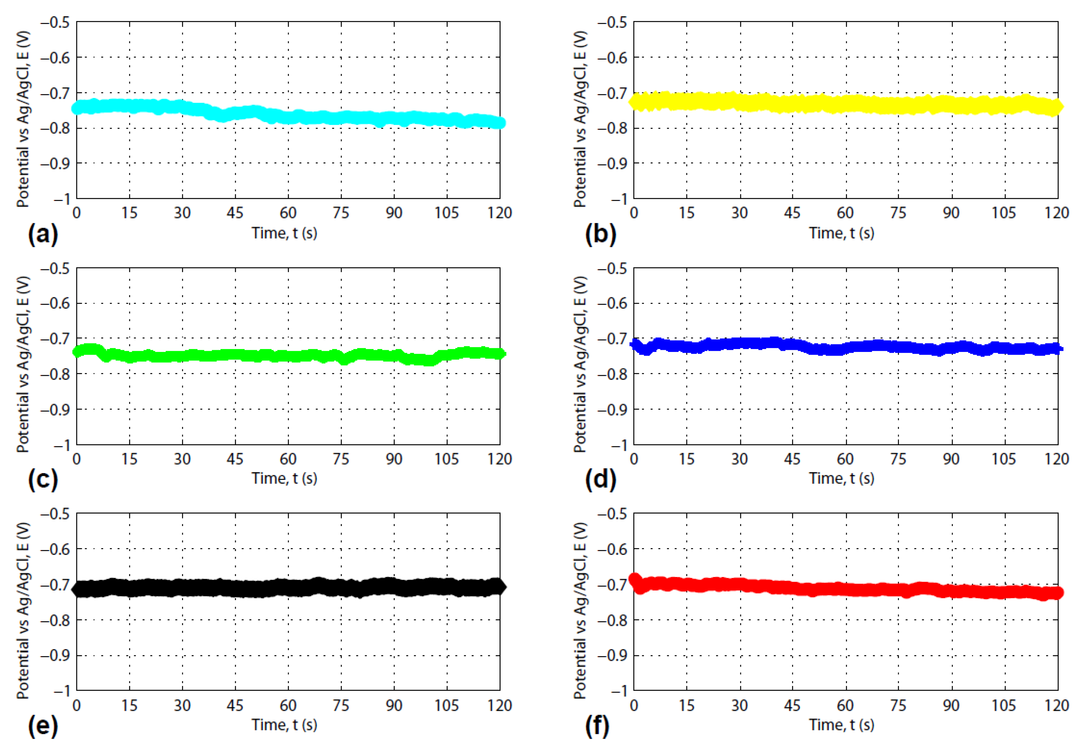
Figure 1. Flowchart showing the procedures for composite carbon fiber processing.
Jcs 04 00156 g001
Figure 2. The three-electrode system for photoelectric response measurement.
Jcs 04 00156 g002
Figure 3. Morphology and elemental analysis result: (a) photos of the cobalt acetate containing polyacrylonitrile (PAN) fibers, (b) scanning electron microscopy (SEM) image of the composite carbon fiber, (c) Energy dispersive X-ray diffraction spectrum (EDS) of the composite fiber.
Jcs 04 00156 g003
Figure 4. Photoelectric response of the fiber electrode in a 5.0 wt.% sodium chloride solution.
Jcs 04 00156 g004
Figure 5. Open circuit potential vs time for the composite carbon fiber electrode in a 5% sugar solution with and without visible light illumination. (The visible light was ON for 15 s followed by 15 s of OFF.).
Jcs 04 00156 g005
Figure 6. Time dependent open circuit potentials for the composite fiber electrode in (a) raspberry juice, (b) orange juice, (c) isopropyl. (The concentration for all solution is the same as 5.0%. The visible light was ON for 15 s followed by 15 s of OFF.).
Jcs 04 00156 g006
Figure 7. Concentration effect on the open circuit potential of the composite fiber electrode in isopropyl water solution: (a) 5% isopropyl, (b) 15% isopropyl, (c) 20% isopropyl, (d) 25% isopropyl, (e) 35% isopropyl, (f) 70% isopropyl. (The visible light was ON for 15 s followed by 15 s of OFF.).
Jcs 04 00156 g007
Table 1. The equilibrium potentials of isopropyl with various concentrations.
Isopropyl Concentration (%)5.010.015.020.025.035.070.0
Equilibrium potential (V)−0.7846−0.7613−0.7325−0.7297−0.7259−0.7129−0.7101
Publisher’s Note: MDPI stays neutral with regard to jurisdictional claims in published maps and institutional affiliations.

