Article

Nanosecond Laser Cutting of Double-Coated Lithium Metal Anodes: Toward Scalable Electrode Manufacturing

1
General Motors Global R&D Center, 30470 Harley Earl Blvd, Warren, MI 48092, USA
2
Institute of Joining and Welding, TU Braunschweig, Langer Kamp 8, 38106 Braunschweig, Germany
3
TRUMPF Laser- und Systemtechnik SE, Johann-Maus-Straße 2, 71252 Ditzingen, Germany
*
Authors to whom correspondence should be addressed.
J. Manuf. Mater. Process. 2025, 9(8), 275; https://doi.org/10.3390/jmmp9080275
Submission received: 8 July 2025 / Revised: 24 July 2025 / Accepted: 1 August 2025 / Published: 11 August 2025

Abstract

The transition to high-energy-density lithium metal batteries (LMBs) is essential for advancing electric vehicle (EV) technologies beyond the limitations of conventional lithium-ion batteries. A key challenge in scaling LMB production is the precise, contamination-free separation of lithium metal (LiM) anodes, hindered by lithium’s strong adhesion to mechanical cutting tools. This study investigates high-speed, contactless laser cutting as a scalable alternative for shaping double-coated LiM anodes. The effects of pulse duration, pulse energy, repetition frequency, and scanning speed were systematically evaluated using a nanosecond pulsed laser system on 30 µm LiM foils laminated on both sides of an 8 µm copper current collector. A maximum single-pass cutting speed of 3.0 m/s was achieved at a line energy of 0.06667 J/mm, with successful kerf formation requiring both a minimum pulse energy (>0.4 mJ) and peak power (>2.4 kW). Cut edge analysis showed that shorter pulse durations (72 ns) significantly reduced kerf width, the heat-affected zone (HAZ), and bulge height, indicating a shift to vapor-dominated ablation, though with increased spatter due to recoil pressure. Optimal edge quality was achieved with moderate pulse durations (261–508 ns), balancing energy delivery and thermal control. These findings define critical laser parameter thresholds and process windows for the high-speed, high-fidelity cutting of double-coated LiM battery anodes, supporting the industrial adoption of nanosecond laser systems in scalable LMB electrode manufacturing.

1. Introduction

Lithium-ion batteries (LIBs) have transformed modern technology, powering a wide range of applications from renewable energy storage systems to electric vehicles. Electric vehicles (EVs) have tremendous potential for a sustainable future with carbon-free and energy-efficient transportation [1]. The current state-of-the-art LIBs (based on graphite anodes) are nearing their theoretical capacity limits (372 mAh/g) [2]. This limitation prevents them from fully addressing consumer concerns about range anxiety and cost. Consequently, there has been a sharp increase in the demand for high-capacity batteries that can power vehicles for long ranges on a single charge. Secondary lithium metal batteries (LMBs) have gained significant attention for their substantially higher energy density, positioning them as a promising solution for high-energy battery packs in EV applications [3,4]. The key differentiating component of LMBs compared to LIBs is the lithium metal (LiM) anode. LiM is considered an ideal anode material due to its inherent advantages, including high specific capacity (3860 mAh/g), low density (0.534 g/cm3), and the lowest electrode potential (−3.04 V) [5]. LMBs do not require any lithium ‘host’ and charge by plating pure Li on the negative electrode (LiM) instead of intercalating it into graphite. Despite the high energy density of LMBs, their implementation is hindered by electrochemical instabilities [5,6]. Researchers have been developing various strategies to mitigate these issues [7,8,9]. Even if the electrochemical performance issues are mitigated, additional challenges persist with the high-volume cell manufacturing of LMBs. These include handling thin lithium metal foils due to lithium’s highly reactive nature as an alkali metal and specific physical and chemical properties of LMBs.
Currently, most activities around the LiM anode and next-generation batteries are focused on research and prototype levels, which require only small quantities of LiM. Therefore, LiM foils are frequently separated manually through the punching process or rudimentary cutting tools such as scissors. Consequently, mass production strategies for larger quantities have not been the focus of current research efforts. One crucial step in cell manufacturing lines that demands high throughput to match web speeds (above 60 m/min) is the separation of electrode foils before the stacking process. Electrodes are made from large, wide rolls of metal foil that, once coated, need to be cut into the desired shape based on the cell format being manufactured. Currently, the most dominant methods for cutting conventional LIB electrode foils in production lines are roll slitting and die cutting. However, mechanical cutting of LiM electrodes results in contamination of the cutting tools due to lithium’s adhesive nature [10]. The material adherence and corresponding cross-contamination could reduce the cut-edge quality and lead to inconsistent electrochemical performance, causing unrepeatable results in large quantities. Therefore, the frequent intensive cleaning of die edges is a prerequisite to alleviate progressive contamination. Permanent tool cleaning stations require significant capital investment and add extra cycle time to manufacturing lines. This predicament renders mechanical separation processes unviable for industrial high-throughput LMB cell manufacturing environments. Therefore, the contactless shaping of LiM anodes using remote laser cutting could be considered a promising alternative, offering several advantages such as high throughput, reproducibility, wear-free operation, and flexibility. Laser cutting has already been investigated in both academia and industry for trimming conventional LIB electrodes in both coated and uncoated regions [11,12,13,14].
In recent years, with a better understanding of process contamination and its effect on cell performance, as well as the behavior of metal spatters and active material particles, laser cutting has transitioned from lab and prototyping levels to mass production lines. This transition includes several applications such as straight-line slitting, notching where tabs are cut into the uncoated element of the foils, and the complete shape cutting of electrodes, which requires cutting both coated and uncoated sections. In addition to continuous wave (CW) lasers [15], pulsed laser systems, including short-pulsed (nanosecond) and ultrashort-pulsed (pico- and femtosecond) lasers [14], are considered ideal for the precise cutting of LIB electrode foils and coated sensitive materials. Their high-frequency energy input in very short intervals minimizes the heat-affected zone, greatly reducing heat conduction and the formation of molten material at the cutting edges [12,16]. Currently, the remote laser cutting of LiM anodes represents the state of the art in next-generation battery technologies. The number of published scientific investigations on the laser separation of LiM electrodes is small. Jansen et al. [17] demonstrated that mechanical cutting is unsuitable for separating free-standing LiM foils. In contrast, laser cutting has proven to be a highly effective method for processing lithium metal foils. However, the achieved maximum cutting speed of 150 mm/s does not meet the criteria required for high-volume production. Eckl et al. [18] have developed a technique for cutting LiM anode layers using a pulsed laser strategy, which can achieve bulge-free cutting edges at speeds of up to 500 mm/s. To address industrial-scale production needs, Kriegler et al. [19] investigated the laser cutting of free-standing lithium metal (LiM) foils using nanosecond pulsed lasers. Their study identified an optimal combination of pulse duration, frequency, and fluence, achieving cutting speeds up to 5.9 m/s with clean edges free of spatter and droplets, making the process well suited for battery manufacturing. Similarly, Heidari Orojloo et al. [20] conducted a comparative study of nanosecond- and picosecond-pulsed laser systems for cutting lithium–copper laminate anodes (single-side-coated), revealing a trade-off between cutting speed and thermal damage. While picosecond pulses minimized the heat-affected zone (HAZ), nanosecond pulses enabled higher cutting speeds up to 5.0 m/s, favoring industrial throughput. As recent studies have primarily addressed free-standing or single-side-coated foils, the behavior of double-coated structures—more relevant to high-volume roll-to-roll and roll-to-sheet manufacturing—remains largely unexplored. Therefore, laser cutting strategies must be adapted to effectively process double-coated LiM anodes laminated on copper or nickel substrates [21].
This study delved into the nano-pulse laser cutting of double-coated LiM anode electrodes, achieving industrial scanning speeds of up to 3 m/s. The primary goal was to determine the highest possible laser cutting speed and to evaluate how the main laser parameters affect the quality of the cuts and the defects that occur during the cutting process. To evaluate the cut quality, optical microscopy and laser scanning microscopy analyses were conducted, focusing on the kerf width, the heat-affected zone (HAZ) width, and bulge height as key characteristics. These characteristics were then correlated with primary process parameters to understand their impact on the cutting performance. The study’s findings provide valuable insights into optimizing laser cutting processes for LiM anodes, demonstrating the potential for achieving a high-speed, precise, and scalable cutting process without compromising cut quality in industrial applications.

2. Ns-Pulsed Laser Cutting

In battery manufacturing, nanosecond pulsed-laser cutting is the most preferred method for electrode cutting. Alternative laser-based processes such as the use of continuous wave lasers or ultrashort pulsed laser systems have also been investigated. It has been established that the utilization of ultrashort pulses results in optimal processing quality [22]. However, these laser systems demonstrate reduced ablation rates and exhibit significantly higher acquisition costs. Given the previously mentioned challenges, laser cutting has emerged as a key technology for the precise, automated, and contactless separation of lithium metal anodes. Its high speed, accuracy, and wear-free operation can significantly boost throughput in industrial battery cell production. However, it is important to note that this technology also poses considerable risks: the concentrated energy exposure of the laser can ignite lithium, thus posing a metal fire risk, particularly in the presence of specific atmospheric conditions during the process [10,23]. A comprehensive understanding of laser–material interaction is essential for achieving high-quality, defect-free cut edges. This requires an in-depth evaluation of the laser parameters that influence the effectiveness of the cutting process. These parameters can be broadly categorized into primary and secondary types, as outlined in Table 1.
The quality of laser cutting is primarily governed by fundamental laser parameters such as spot diameter, laser power, feed rate, and pulse frequency. These core parameters critically influence the laser–material interaction, directly affecting the formation of heat-affected zones (HAZs) and the overall cut edge quality.
In addition to these primary parameters, secondary laser parameters provide a more detailed and quantitative framework for characterizing and optimizing the cutting process. These parameters not only enhance control over process outcomes but also support scalability to higher-power laser systems and adaptability across different laser platforms. The following mathematical expressions define key secondary parameters relevant to laser cutting optimization.
Pulse energy (Ep) defines as the amount of energy delivered in a single laser pulse, which significantly influences the interaction between the laser beam and the material. It is calculated as
E p = P P R F
where P is the laser power and PRF is the pulse repetition frequency.
Laser intensity (I) represents the power density of the laser beam over a defined area, which significantly influences material removal and melt pool dynamics. It is given by Equation (1):
I = P A s p o t
where Aspot is the area of the laser spot.
Line energy (EL) represents the energy delivered per unit length along the cutting path. It is a function of laser power and cutting velocity, and it significantly influences the thermal effects in the material. It is calculated as follows:
E L = P V c
where Vc is the cutting velocity.
Pulse overlap (PO) describes the degree of overlap between successive laser pulses, which affects the uniformity and smoothness of the cut. Higher overlap generally improves cut quality but may increase thermal loading. It is defined as follows:
P O = 1 V c P R F d s p o t 100
where dspot is the laser spot diameter. Figure 1 schematically illustrates the concept of pulse overlap and its influence on pulse distribution along the cutting path.
By precisely adjusting the secondary parameters, both the quality and efficiency of the laser cutting process can be further optimized. This approach enables tailored process strategies for different materials and cutting requirements, contributing to the improved performance and broader applicability of laser-based manufacturing technologies.

3. Experimental Procedure

3.1. Materials, Laser System and Cutting Setup

In this study, to conduct cutting experiments, industrially available lithium metal anodes were used (Honjo Metal Co. Ltd., Japan). The high-purity lithium foil, with a nominal thickness of 30 µm, was laminated on both sides of an 8 µm copper foil current collector (Figure 2). Measurements taken at 20 different points along the roll indicated a thickness of 30.5 ± 0.7 µm. Strips of LiM anode were cut from a 10 m roll to conduct cutting experiments.
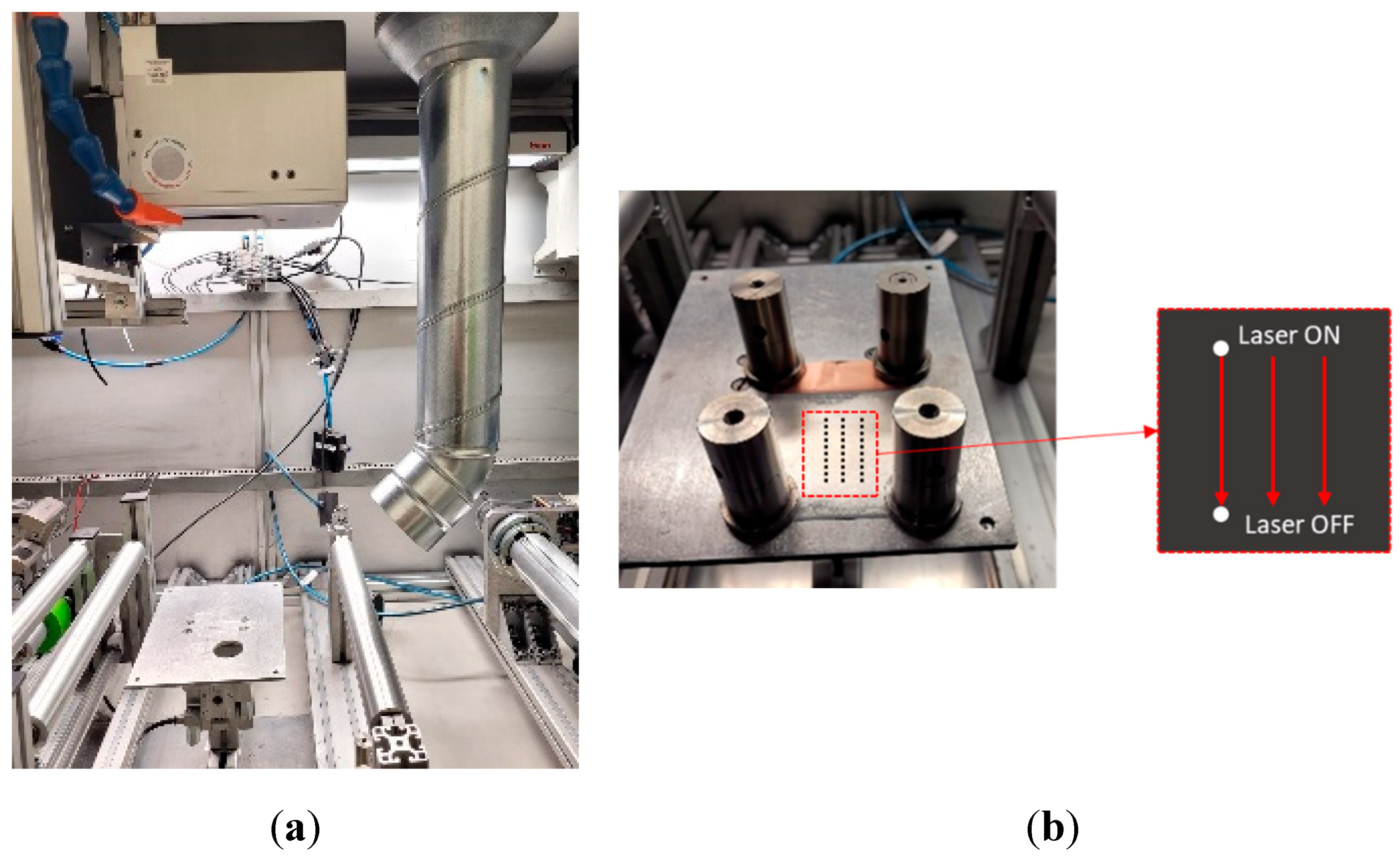
The experiment utilized a nanosecond pulsed fiber laser that operates in the near IR region with a central wavelength at 1064 nm (TruPulse 2020 nano, TRUMPF SE + Co. KG, Ditzingen, Germany). The laser outputs an average power of 200 W and a peak pulse power of up to 10 kW, featuring an M2 < 1.3. For beam delivery, the laser source was connected to a beam-expanding collimator (F75), which results in a raw beam with a diameter of 7.5 mm. This was followed by a post-objective laser scanner (Axialscan 30 Digital II, Raylase GmbH, Weßling, Germany) for beam movement. The optical configuration resulted in a spot diameter of 60 µm at the focal plane and a scanning field size of 400 × 400 mm2. The experimental setup is illustrated in Figure 3. In this study, a post-objective scanner (with the focusing lens placed before the scanning mirrors) was chosen over a pre-objective scanner (where the F-theta focusing lens was placed after the scanning mirrors) due to its advantage of offering a larger scanning field size. This enabled the investigation of cutting larger contours of LiM anodes in roll-to-roll and roll-to-sheet applications in a single pass. For example, a pre-objective system with a comparable spot size and the same raw beam diameter, using an F255 objective, would result in a scanning field size of approximately 130 × 130 mm2. In contrast, the post-objective system provides a significantly larger scanning field size of about 400 × 400 mm2. Although the larger field size results in a lower scanning speed (10 m/s for the post-objective system versus approximately 40 m/s for the pre-objective system), the cutting speed for coated electrodes is generally below 10 m/s. Therefore, the disadvantage of a lower scanning speed does not impact this experimental setup; instead, the benefit of a larger scanning field size can be explored.
Due to the highly moisture-sensitive nature of lithium, the cutting experiments had to be conducted in an atmosphere-controlled environment. The laser cutting system was placed inside a dry room with a dew point of −35 °C, a temperature of 20 °C, and a relative humidity level of 1.3%. The system was also equipped with a dedicated exhaust and filtration system to remove the metal vapor generated during the process. Strips of LiM anode foils were cut from a roll and placed on a cutting fixture with an existing slit. Weights were used to secure the foils under tension and keep them precisely in position during the cutting process (Figure 3b). The top surface of the fixture was positioned at the focal point under the scanner for static cutting operations. Parallel laser cuts, each 30 mm in length, were performed for each case. To avoid thermal interaction and local deviations from the nominal focal plane, a lateral distance of 6 mm was maintained between the cuts.
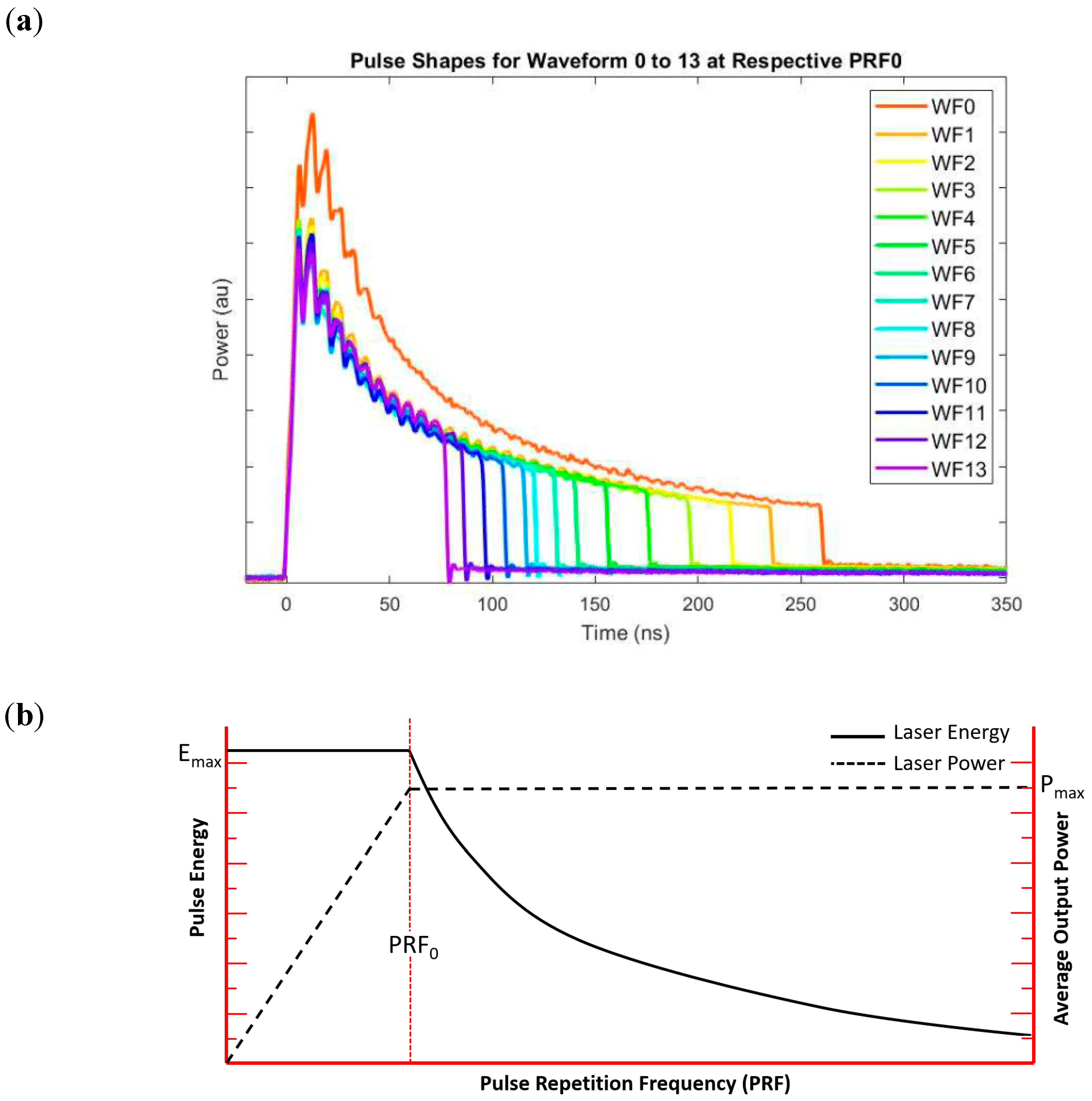
The TruPulse laser has an integrated pulse tune functionality feature to generate pulse shapes (Waveforms), which is based on the MOPA (Master Oscillator Power Amplifier) architecture. This ability allows us to adjust the pulse characteristics by selecting specific waveform numbers. The TruPulse nanolaser operates such that it outputs its maximum pulse energy for a given waveform and pulse duration at its base frequency (PRF0). Figure 4a presents examples of pulse waveform shapes at the base frequency. When the frequency is increased from PRF0, the pulse peak power and eventually pulse energy are reduced while the average power stays the same; however, reducing the frequency from PRF0 decreases the average power linearly. This characteristic is shown in Figure 4b.

3.2. Analysis of Cut Edge

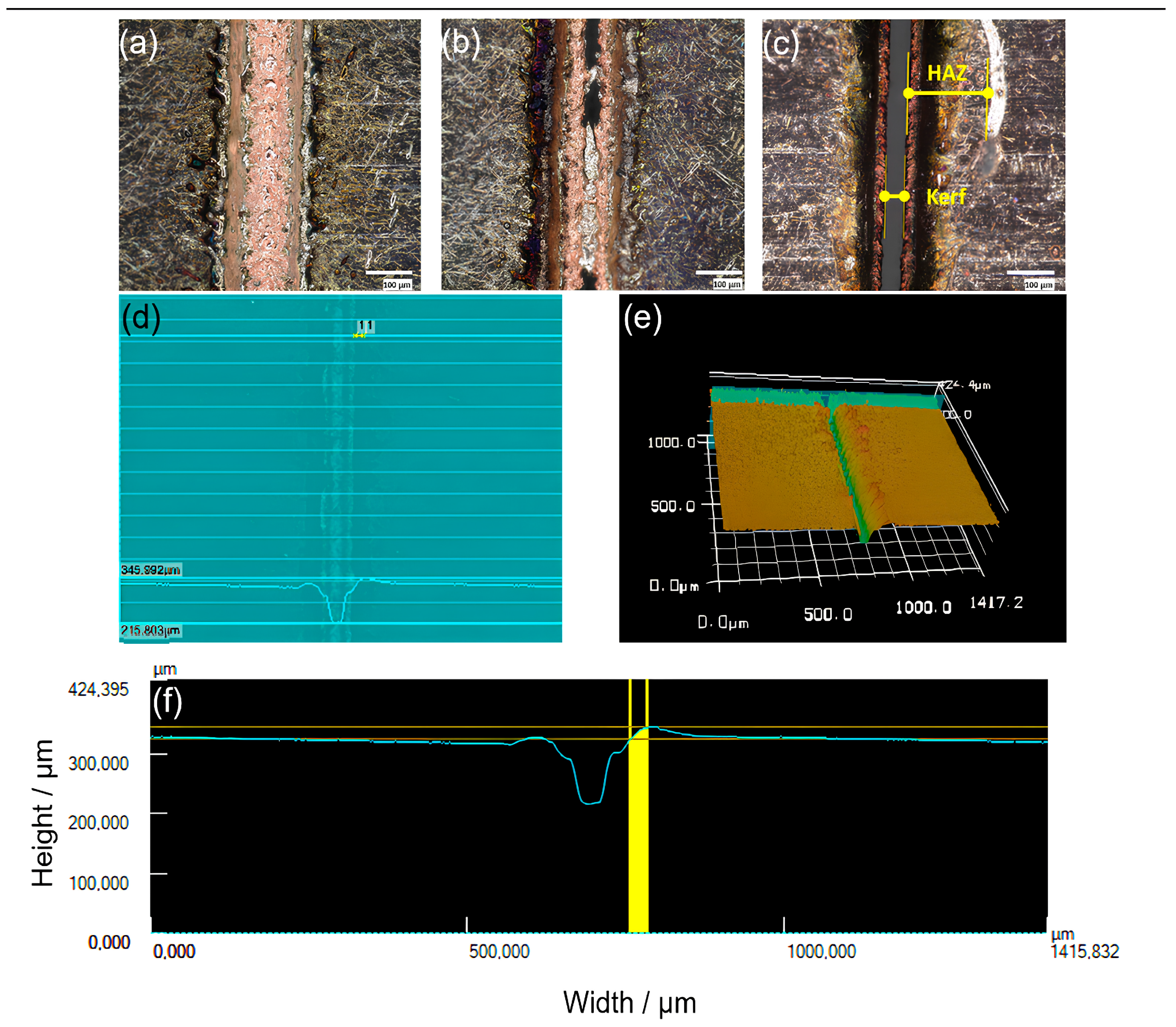
The interaction between the laser and the lithium material results in distinct characteristics at the cut edge, including the HAZ, bulge, and spatter. These thermal effects can significantly influence the electrochemical behavior of the lithium anode by altering its microstructure, leading to localized recrystallization or phase changes that increase resistance and negatively impact battery performance [24]. Additionally, uneven surfaces can cause inhomogeneous current density distribution, increasing the risk of dendrite formation and internal short circuits [25]. Particles ejected during laser cutting can redeposit on the lithium surface, creating hotspots of increased reactivity and enhancing side reactions with the electrolyte, leading to gas formation and battery swelling [26]. Therefore, an optimal set of cutting process parameters should address these challenges by achieving the best possible cutting characteristics. To evaluate cut quality and process performance, optical microscopy (Model VHX-2000 Keyence, Osaka, Japan) and laser scanning microscopy (Model VK-9710, Keyence, Osaka, Japan) were utilized. Image analysis and quantification were performed using the VK Analyzer software provided by Keyence. The cutting results were categorized into three groups: “Cut”, “Partial Cut”, and “No Cut.” A sample was classified as “Cut” if it exhibited a complete and continuous kerf along the laser path. “Partial Cut” referred to samples with incomplete cuts or irregularities along the cut edge. Samples that showed only the ablation of the LiM coating at the laser entry side, without penetrating the copper foils, were categorized as “No Cut.” Only samples meeting the “Cut” criteria were selected for further quantitative analysis. To evaluate the cut quality, kerf width, heat-affected zone (HAZ) width, and bulge height values were measured for selected samples. Representative results from the three different cutting conditions are presented in Figure 5a–c, with Figure 5c highlighting the characteristic kerf and HAZ features observed in “Cut” samples. The bulge height, defined as the elevation of lithium above the initial thickness of the coated layer, is illustrated in Figure 5d. For each selected sample, five to six measurement points were obtained along the 30 mm laser cutting path. To minimize the influence of effects associated with the start and end of the cut process, measurements were taken at positions corresponding to approximately 30%, 50%, and 70% of the path length.

4. Results and Discussion

4.1. Laser Parameter Effects on Cutting Performance

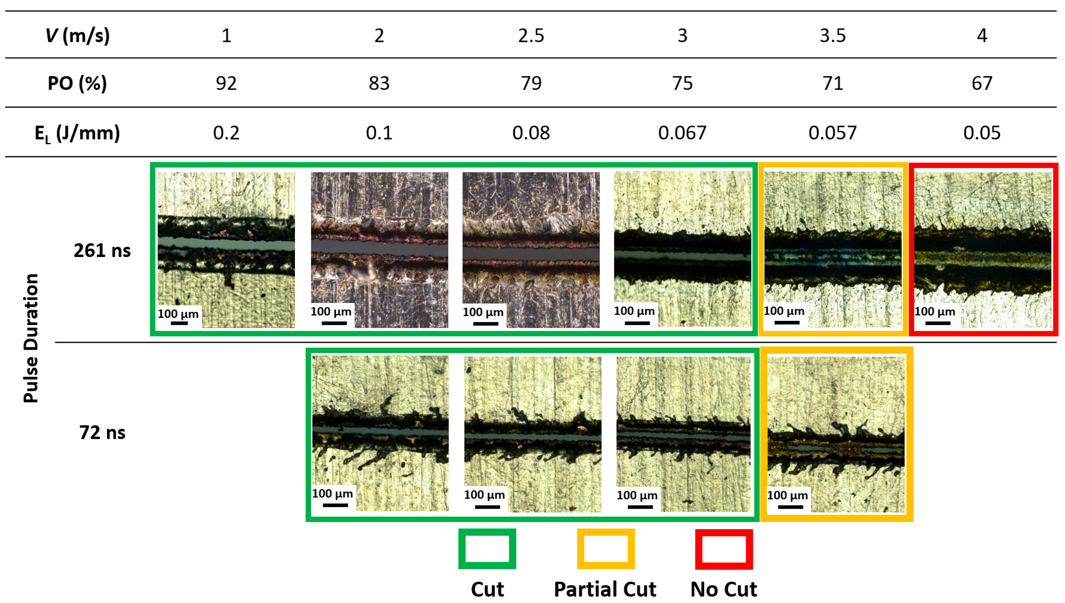
As the objective of the study was to achieve high cutting speeds with reliable quality, an initial round of testing was carried out to determine the maximum achievable cutting speed (Vmax) in a single-pass laser cutting process. Vmax is defined as the highest scanning speed at which a stable and continuous cutting kerf can be produced, without the presence of incomplete material separation. To investigate this, experiments were conducted using two different pulse durations: 72 nanoseconds (ns) and 261 ns. These durations represent short and long pulse regimes, respectively, which are known to have distinct pulse profiles and energy delivery characteristics with the material. The laser power was fixed at 200 W (the maximum output power of the laser system) to ensure that the full capacity of the system was utilized during these trials. The scanning speed was increased in increments of 500 mm/s until a threshold was reached, beyond which full material penetration and clean kerf formation could no longer be maintained. This stepwise approach enabled the precise identification of the Vmax for each pulse duration. It is important to note that pulse energy is a function of both laser power and pulse repetition frequency (PRF), as outlined in Equation (1). Therefore, to isolate the effect of scanning speed and avoid fluctuations in pulse energy, the PRF was kept constant at the base repetition rate (PRF0) for each respective pulse duration, 510 kHz for 72 ns and 200 kHz for 261 ns. This approach resulted in fixed pulse energies during the tests: 1.03 mJ for the 261 ns pulses and 0.41 mJ for the 72 ns pulses. Maintaining a constant pulse energy ensured that the observed changes in cutting performance could be attributed primarily to the variation in scanning speed, rather than confounding effects of varying energy per pulse. As shown in Figure 6, cut quality progressively deteriorates with increasing scanning speed in both cases. Continuous cuts with the absence of uncut bridges were achieved up to a maximum scanning speed of 3 m/s, beyond which the kerf quality transitioned into partial cuts (yellow borders) or no cuts (red borders). This establishes 3 m/s as the maximum achievable single-pass cutting speed for full cuts under these specific energy and pulse duration conditions.
It is noteworthy that at 72 ns pulse duration, while a continuous kerf was achieved at 3 m/s, significant spatter along the kerf edges was observed. This is likely caused by the combination of the short pulse duration and high repetition rate, which increases the peak power intensity (~198.9 MW/cm2), leading to more explosive material removal and the lateral ejection of molten material, as evident in the micrographs. While high peak power enhances ablation efficiency, it also induces strong recoil pressure in the melt pool, promoting instability and spatter [14]. As discussed in Section 3.2, such irregularities may hinder downstream processing or cell performance. Therefore, despite achieving a full cut, excessive spatter limits the practical applicability of the 72 ns pulse condition. These results demonstrate that the longer pulse duration (261 ns) enables more stable cutting, yielding superior kerf quality and cleaner edges compared to the shorter 72 ns pulse under otherwise identical conditions. Pulse overlap (PO) decreased with increasing scanning speed, ranging from 92% at 1.0 m/s to 67% at 4.0 m/s. This directly impacted the line energy (as per Equation (3)), which declined from 0.2 J/mm to 0.05 J/mm over the same range. As both PO and line energy are critical for delivering sufficient thermal input, their reduction at higher speeds led to incomplete or unstable cuts [11]. The maximum speed for achieving a clean, continuous cut was 3.0 m/s, corresponding to 75% PO and 0.067 J/mm line energy. These results highlight clear thresholds for effective cutting with a minimum PO of ~75% and line energy ≥0.067 J/mm, which are required to ensure stable kerf formation. Dropping below these limits compromises cut quality and consistency, as demonstrated in Figure 6.
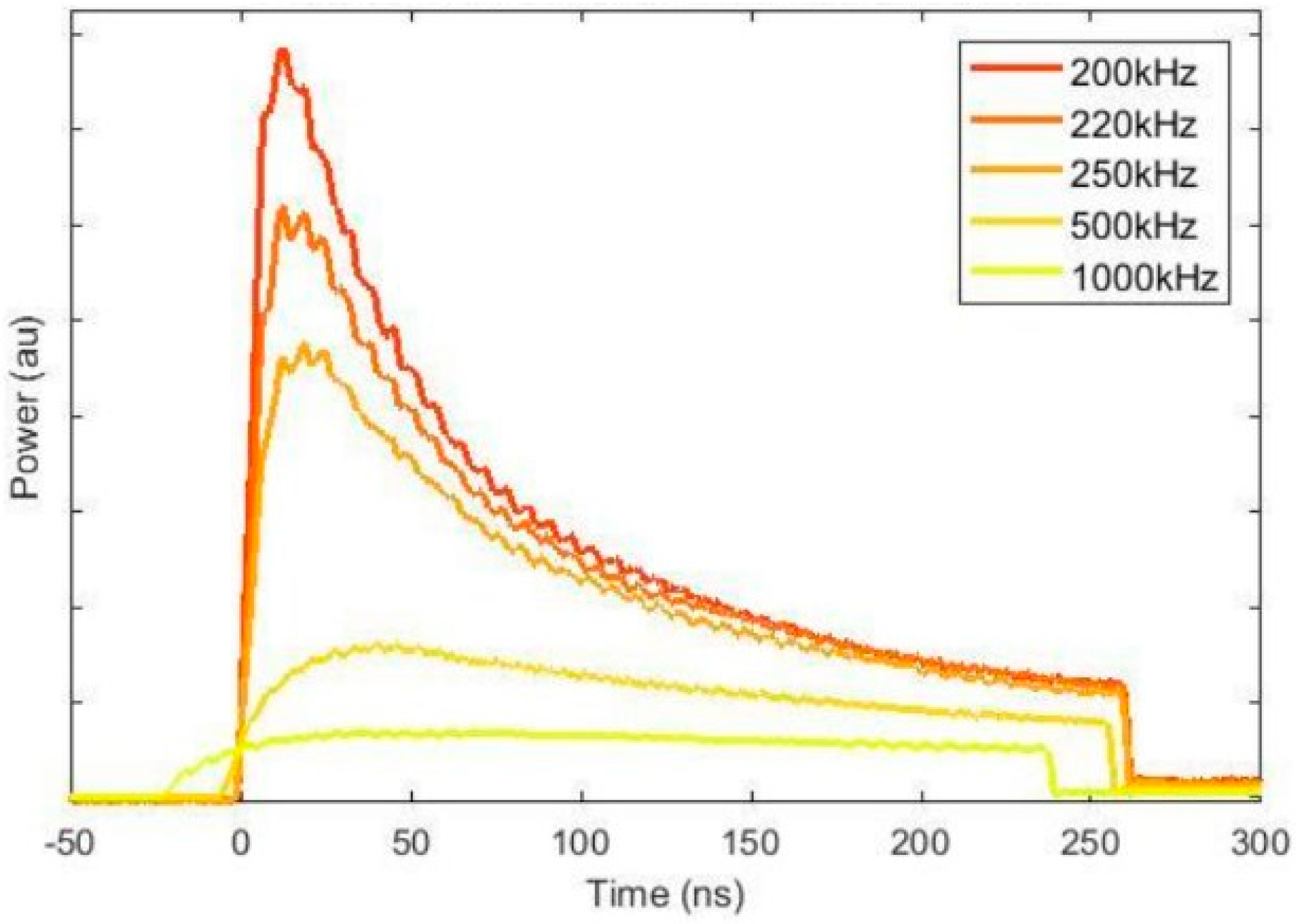
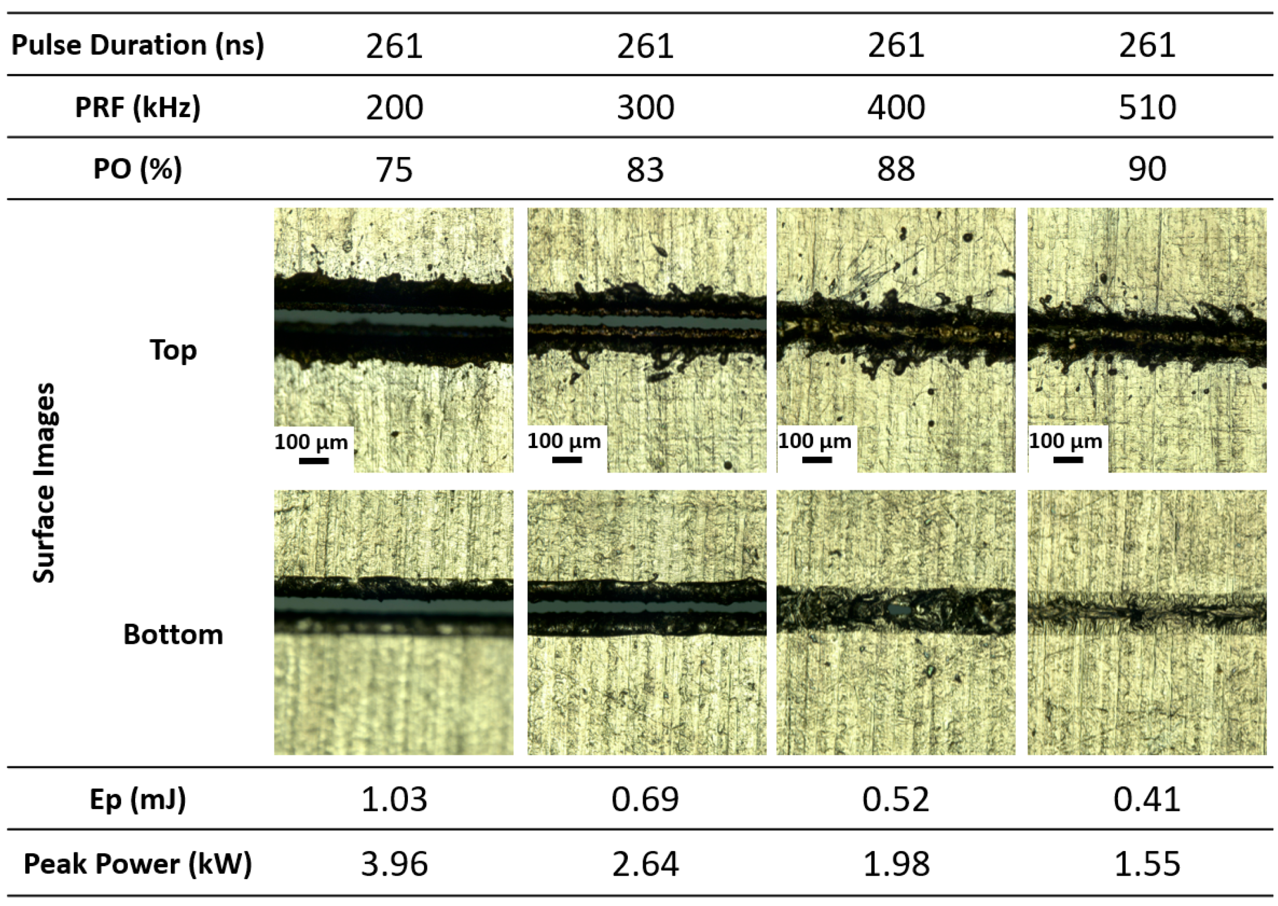
At a fixed pulse duration of 261 ns, varying the pulse repetition rate from 200 kHz (PRF0) to 510 kHz while maintaining a constant scanning speed (3 m/s) and line energy (0.06667 J/mm) reveals a critical interplay between pulse overlap, energy delivery, and cutting performance. As the PRF increases, pulse overlap improves from 75% to 90%, enhancing the spatial uniformity of energy distribution along the cut path. However, this improvement in overlap comes at the cost of reduced pulse energy (from 1.03 mJ to 0.41 mJ) and peak power (from 3.96 kW to 1.55 kW). As shown in Figure 7, the decrease in peak power—confirmed by pulse shape profiles—results in a pronounced flattening of the temporal power envelope at higher PRFs, thereby limiting the generation of recoil pressure and localized vaporization necessary for efficient ablation [27].
The analysis of laser cut images on both sides of laser entrance and exit reveals a clear deterioration in cut quality with increasing pulse repetition frequency (PRF), characterized by reduced penetration depth, increased dross accumulation, and irregular kerf morphology. This decline is attributed to the reduction in per-pulse energy and peak power at higher PRFs. Experimental evidence indicates that meeting the pulse energy threshold alone is insufficient to ensure successful cutting. For instance, at higher PRFs corresponding to pulse durations of 400 and 510 ns, cuts were unsuccessful despite pulse energies exceeding 0.4 mJ. This highlights the presence of a dual-threshold condition, where both pulse energy (>~0.4 mJ) and peak power (>~2.4 kW) must be met to maintain effective melt ejection and continuous cutting. These findings, supported by the observations in Figure 8, underscore the importance of balancing pulse overlap with sufficient instantaneous power when optimizing PRF for high-speed laser processing. Failure to maintain this balance compromises ablation efficiency, even when line energy remains constant, emphasizing the critical role of temporal energy delivery in laser–material interaction.
At a fixed scanning speed of 3 m/s and constant line energy of 0.06667 J/mm, the effects of varying pulse duration, pulse energy, and peak power were investigated to decouple their respective contributions to cut quality. While all tested conditions delivered the same energy per unit length, the temporal distribution of that energy had a strong influence on the material response and cutting outcome. The conditions that produced successful cuts are highlighted in the green box in Figure 9. Short pulse durations such as 29 ns and 72 ns, operating at high PRFs (1000 kHz and 510 kHz, respectively), generated extremely high peak powers (7.12 kW and 5.63 kW) but low pulse energies (0.21 mJ and 0.41 mJ). These conditions promoted rapid ablation and strong recoil pressure, facilitating material removal but also leading to unstable melt dynamics, excessive spatter, and degraded kerf quality. As shown in Figure 9, the 29 ns case failed to produce any cut despite the highest peak intensity (251.96 MW/cm2), highlighting that high peak power alone is insufficient without adequate pulse energy. In contrast, the 72 ns condition achieved cutting due to its higher pulse energy, but the kerf exhibited irregularities and spatter accumulation. These observations point to a critical pulse energy threshold (~0.4 mJ) below which effective cutting cannot be sustained, regardless of intensity, emphasizing that both pulse energy and duration must be carefully optimized in high-speed laser processing. In contrast, moderate pulse durations such as 261 ns and 508 ns demonstrated superior cutting performance, offering a balanced combination of pulse energy (1.03 mJ and 1.24 mJ) and peak power (3.96 kW and 2.45 kW). These conditions facilitated stable melt pool dynamics, resulting in smooth, continuous cuts with clean kerf edges and minimal spatter or thermal damage. On the other end, the long pulse duration of 1220 ns, despite delivering the highest pulse energy (1.52 mJ) and lowest peak power (1.25 kW), failed to achieve any cutting. The observed lack of penetration indicates that peak power was insufficient to induce vaporization or effective melt ejection. This underscores the necessity of achieving a minimum peak power to activate recoil pressure-driven melt expulsion, making it as a key factor alongside line energy for successful laser cutting.

4.2. Effect of Cutting Parameters on Edge Quality

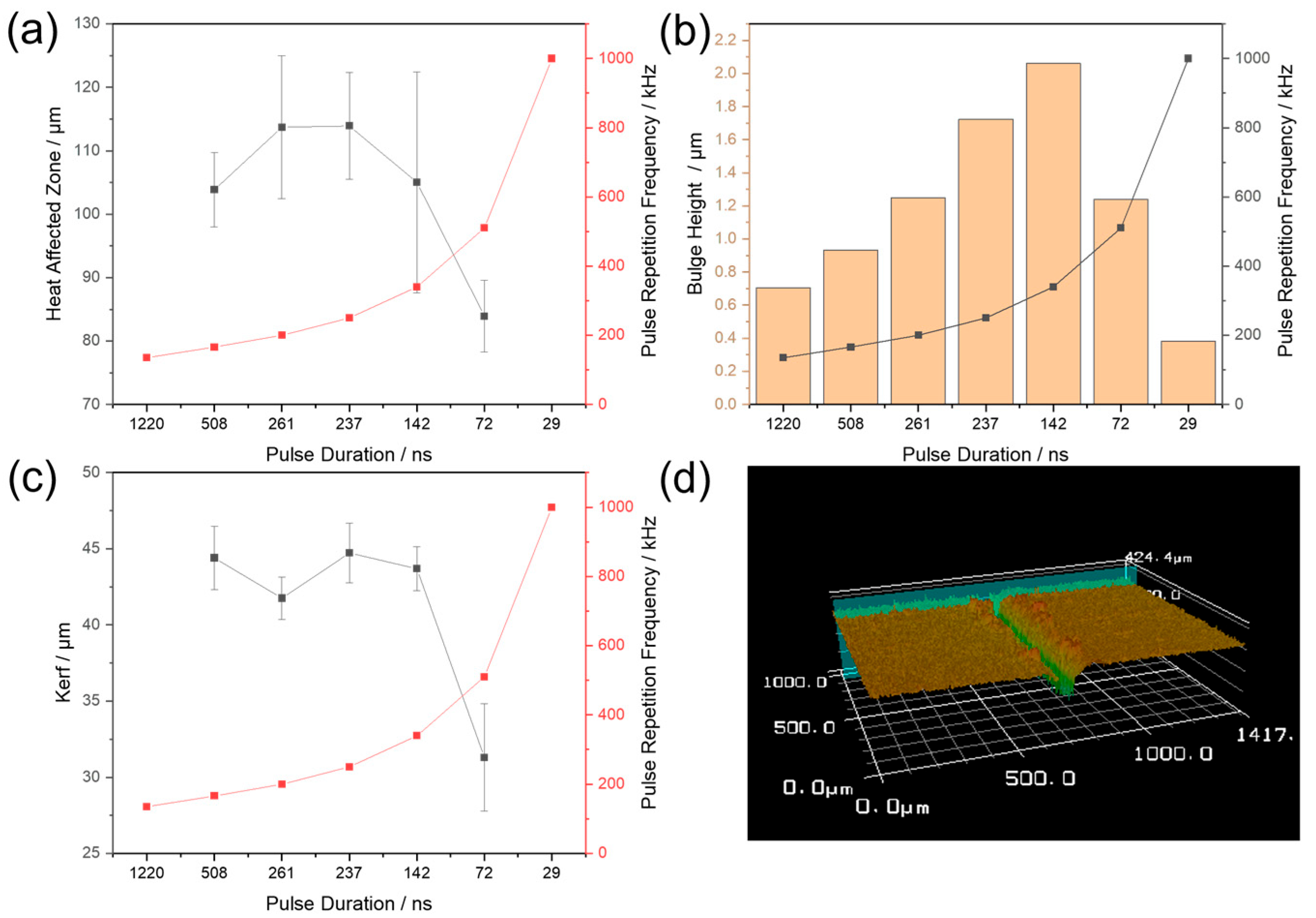
In this section, the influence of laser pulse duration and pulse repetition frequency (PRF) on the cut quality and thermal response of the material is systematically investigated within a defined parameter space as highlighted in Figure 9. The experiments were conducted at a constant feed rate of 3 m/s. The primary focus of this section is the characterization of the heat-affected zone (HAZ), the kerf width, and the extent of bulge height as a function of the applied laser parameters. The quantitative data and corresponding graphs are shown Figure 10.
A discernible trend is observed in the morphological characteristics of the cut edges as pulse duration decreases and repetition frequency increases. Between 508 ns and 142 ns, both the HAZ and kerf width remain relatively consistent, with variations largely falling within the standard deviation of the measurements, suggesting a stable and quasi-steady laser–material interaction. However, a notable and substantial decrease in both the HAZ and the kerf width is evident at a pulse duration of 72 ns. This pronounced decrease signifies the threshold in the interaction dynamics.
In contrast to the trends observed for the HAZ and kerf width, bulge height exhibits an opposing behavior across the pulse duration range. As the pulse duration decreases from 1220 ns to 142 ns, there is a noticeable increase in the accumulation of molten material along the cut edges. Although complete material separation is not achieved at 1220 ns, visual inspection and quantitative analysis reveal that material displacement is already occurring, forming raised melt ridges along the kerf. This elevation becomes more pronounced with shorter pulse durations, indicating that a larger fraction of the laser energy contributes to melting rather than vaporization, leading to inefficient material removal and broader thermal impact. However, at 72 ns, this trend sharply reverses, marking a transition into a highly efficient ablation regime. In this regime, the laser pulses are sufficiently short to confine energy deposition both spatially and temporally, resulting in a marked reduction in kerf width, the HAZ, and bulge height [20]. This improved cut fidelity is attributed to enhanced vaporization, minimized melt formation, and suppressed thermal diffusion. At 72 ns, the combination of confined energy delivery and high peak power results in clean cuts with minimal melt deposition and limited thermal impact. Overall, this pulse regime—characterized by a short duration and high PRF—defines an optimal process window for producing narrow kerfs, a suppressed HAZ, low bulge height, and high thermal confinement [14].
However, this high-efficiency regime is not without trade-offs. Surface inspections at 72 ns reveal noticeable spatter deposition around the cut edges, attributed to the high peak power (5.63 kW) and elevated pulse intensity that promote explosive vaporization and recoil pressure-driven melt ejection. The rapid energy delivery surpasses the material’s capacity for smooth heat dissipation, triggering micro-explosive events that eject partially molten or vaporized particles from the interaction zone. This phenomenon is particularly evident in the LSM images (Figure 10d), where microscopic droplets and debris trails are observed adjacent to the kerf walls. Lithium and copper exhibit significantly different thermal properties that influence their laser–material interaction during cutting. Lithium has a low melting point of 180.5 °C and a boiling point of 1342 °C, while copper melts at 1085 °C and boils at 2562 °C. These differences mean that under pulsed laser irradiation, lithium enters the melting and vaporization regimes much earlier than copper, leading to distinct ablation behaviors at the interface. Due to lithium’s low melting point and high reactivity, it tends to melt and vaporize rapidly when exposed to high peak power pulses, especially in vapor-dominated ablation regimes induced by short pulse durations. This enhances material removal efficiency but also promotes spatter and bulge formation due to explosive vaporization. In contrast, copper’s higher thermal thresholds require more sustained energy input to reach melting or vaporization, often leading to localized heat accumulation near the interface. This thermal mismatch between the two materials can result in asymmetric cut profiles and uneven kerf morphology.
This behavior highlights a critical balance: although shorter pulse durations enhance cut precision and reduce bulge height, they also increase the likelihood of mechanically violent ejection events—especially in low-viscosity materials like lithium. At this pulse regime, energy coupling becomes increasingly governed by photomechanical effects, such as recoil pressure and plasma expansion, rather than by steady-state thermal melting. This transition shifts the ablation mechanism from melt-dominated to vapor-dominated removal, explaining the sharp decline in bulge height at 72 ns while concurrently increasing spatter generation—a characteristic feature of high-fluence, vapor-dominated laser ablation regimes.

5. Conclusions

This study presents a comprehensive investigation into the high-speed nanosecond laser cutting of double-coated lithium metal (LiM) anodes, a key enabler for next-generation lithium metal batteries (LMBs). The anode material consisted of high-purity lithium foil (30 µm thick) laminated on both sides of an 8 µm copper foil current collector, reflecting industrially relevant battery configurations. These double-coated structures pose unique challenges for precision processing due to lithium’s high reactivity, low melting point, and strong adhesion to mechanical tooling. To address the limitations of conventional mechanical cutting, this work evaluates contactless, high-throughput laser separation using a nanosecond short-pulsed fiber laser. The influence of key laser parameters—including pulse duration, pulse energy, repetition frequency, and scanning speed—was systematically studied to identify optimal process conditions for industrial-scale, high-fidelity cutting.
Key findings include the following:
  • A maximum single-pass cutting speed of 3.0 m/s was achieved at a constant line energy of 0.067 J/mm. This speed represents a practical upper limit under the tested conditions for maintaining continuous kerf formation without incomplete cuts.
  • Pulse duration and energy distribution were found to critically influence cut quality. While short pulses (e.g., 72 ns) enabled efficient ablation through high peak power, they also introduced excessive spatter due to explosive vaporization. In contrast, moderate pulse durations (261–508 ns) provided a more balanced energy delivery, resulting in clean kerfs with minimal thermal damage and melt accumulation.
  • A dual-threshold condition was identified for effective cutting: both pulse energy (>~0.4 mJ) and peak power (>~2.4 kW) are required to generate sufficient recoil pressure for stable melt ejection.
  • Morphological analysis revealed that shorter pulse durations markedly reduce the heat-affected zone (HAZ) width, kerf width, and melt bulge height, indicating a shift toward a vapor-dominated ablation regime. However, this regime also increases the likelihood of spatter formation due to intensified recoil pressure, highlighting a trade-off between cutting precision and surface cleanliness.
  • The results emphasize the importance of temporal energy delivery and pulse overlap in optimizing laser–material interactions, particularly for reactive and low-viscosity materials like lithium.
This study establishes a solid foundation for the scalable, laser-based processing of double-coated lithium metal (LiM) anodes, demonstrating that high-speed, high-quality cutting is achievable through the careful optimization of short-pulsed laser parameters. The results directly support industrial implementation in roll-to-roll and roll-to-sheet manufacturing environments, where precision and throughput are critical. Looking forward, this study opens avenues for further process refinement by investigating additional manufacturing variables such as defocused laser beams to control energy density, beam positioning within the scan field to minimize edge artifacts, and the influence of cutting path geometries (e.g., radii vs. linear) on kerf morphology. These future efforts will enhance process robustness and adaptability, accelerating the industrialization of laser-based electrode shaping for next-generation lithium metal battery production.

Author Contributions

Conceptualization, M.M.P. and L.O.S.; methodology, M.M.P. and L.O.S.; software, V.S. and H.G.; validation, M.M.P., formal analysis, M.M.P., L.O.S. and V.S.; investigation, V.S. and H.G. resources, M.M.P. and B.E.C.; data curation, M.M.P. and L.O.S.; writing—original draft preparation, M.M.P. and L.O.S.; writing—review and editing, G.A., O.B., V.S. and M.W.K.; visualization, M.M.P.; supervision, M.W.K. All authors have read and agreed to the published version of the manuscript.

Funding

This research received no external funding.

Data Availability Statement

The original contributions presented in this study are included in the article, and further inquiries can be directed to the corresponding author.

Conflicts of Interest

The authors declare no conflicts of interest.

References

  1. Shaffer, B.; Auffhammer, M.; Samaras, C. Make electric vehicles lighter to maximize climate and safety benefits. Nature 2021, 598, 254–256. [Google Scholar] [CrossRef]
  2. Xu, W.; Wang, J.; Ding, F.; Chen, X.; Nasybulin, E.; Zhang, Y.; Zhang, J.-G. Lithium metal anodes for rechargeable batteries. Energy Environ. Sci. 2014, 7, 513–537. [Google Scholar] [CrossRef]
  3. Winter, M.; Barnett, B.; Xu, K. Before Li Ion Batteries. Chem. Rev. 2018, 118, 11433–11456. [Google Scholar] [CrossRef] [PubMed]
  4. Albertus, P.; Babinec, S.; Litzelman, S.; Newman, A. Status and challenges in enabling the lithium metal electrode for high-energy and low-cost rechargeable batteries. Nat. Energy 2018, 3, 16–21. [Google Scholar] [CrossRef]
  5. Wang, R.; Cui, W.; Chu, F.; Wu, F. Lithium metal anodes: Present and future. J. Energy Chem. 2020, 48, 145–159. [Google Scholar] [CrossRef]
  6. Gao, X.; Zhou, Y.-N.; Han, D.; Zhou, J.; Zhou, D.; Tang, W.; Goodenough, J.B. Thermodynamic Understanding of Li-Dendrite Formation. Joule 2020, 4, 1864–1879. [Google Scholar] [CrossRef]
  7. Guo, F.; Wu, C.; Chen, H.; Zhong, F.; Ai, X.; Yang, H.; Qian, J. Dendrite-free lithium deposition by coating a lithiophilic heterogeneous metal layer on lithium metal anode. Energy Storage Mater. 2020, 24, 635–643. [Google Scholar] [CrossRef]
  8. Park, S.K.; Copic, D.; Zhao, T.Z.; Rutkowska, A.; Wen, B.; Sanders, K.; He, R.; Kim, H.-K.; De Volder, M. 3D Porous Cu-Composites for Stable Li-Metal Battery Anodes. ACS Nano 2023, 17, 14658–14666. [Google Scholar] [CrossRef]
  9. Cui, Y.; Liu, S.; Liu, B.; Wang, D.; Zhong, Y.; Zhang, X.; Wang, X.; Xia, X.; Gu, C.; Tu, J. Bi-containing Electrolyte Enables Robust and Li Ion Conductive Solid Electrolyte Interphase for Advanced Lithium Metal Anodes. Front. Chem. 2020, 7. [Google Scholar] [CrossRef]
  10. Jansen, T.; Hartwig, S.; Blass, D.; Dilger, K. Laser cutting of pure lithium metal anodes—Effects of atmospheric conditions. In Proceedings of the ICALEO 2017: 36th International Congress on Applications of Lasers & Electro-Optics, Atlanta, GA, USA, 22–26 October 2017. [Google Scholar]
  11. Jansen, T.; Kandula, M.W.; Hartwig, S.; Hoffmann, L.; Haselrieder, W.; Dilger, K. Influence of Laser-Generated Cutting Edges on the Electrical Performance of Large Lithium-Ion Pouch Cells. Batteries 2019, 5, 73. [Google Scholar] [CrossRef]
  12. Kriegler, J.; Binzer, M.; Zaeh, M.F. Process strategies for laser cutting of electrodes in lithium-ion battery production. J. Laser Appl. 2020, 33. [Google Scholar] [CrossRef]
  13. Marc, S.; Adam, R.; Jack, G.; Axel, F.; Lin, L.; Daniel Huerta, M. High-throughput battery foil cutting: A comparison of different pulsed laser approaches. In Proceedings of the Laser-based Micro- and Nanoprocessing XVII, San Francisco, CA, USA, 31 January–2 February 2023; SPIE: Bellingham, WA, USA; Volume 12409, p. 124090M. [Google Scholar]
  14. Zhang, Y.; Li, J.; Yang, R.; Liu, T.; Yan, Y. Analysis of kerf quality on ultrafast laser cutting of anode material for lithium-ion battery. Opt. Lasers Eng. 2019, 118, 14–21. [Google Scholar] [CrossRef]
  15. Lee, D.; Patwa, R.; Herfurth, H.; Mazumder, J. High speed remote laser cutting of electrodes for lithium-ion batteries: Anode. J. Power Sources 2013, 240, 368–380. [Google Scholar] [CrossRef]
  16. Luetke, M.; Franke, V.; Techel, A.; Himmer, T.; Klotzbach, U.; Wetzig, A.; Beyer, E. A Comparative Study on Cutting Electrodes for Batteries with Lasers. Phys. Procedia 2011, 12, 286–291. [Google Scholar] [CrossRef]
  17. Jansen, T.; Blass, D.; Hartwig, S.; Dilger, K. Processing of Advanced Battery Materials—Laser Cutting of Pure Lithium Metal Foils. Batteries 2018, 4, 37. [Google Scholar] [CrossRef]
  18. Eckl, M.J.; Mäder, G.; Roch, J.; Thümmler, P.; Abendroth, T. Method and Device for Cutting a Metal-Containing Foil, and Laser-Cut Metal-Containing Foil. U.S. Patent 18/551,774, 30 May 2024. [Google Scholar]
  19. Kriegler, J.; Duy Nguyen, T.M.; Tomcic, L.; Hille, L.; Grabmann, S.; Jaimez-Farnham, E.I.; Zaeh, M.F. Processing of lithium metal for the production of post-lithium-ion batteries using a pulsed nanosecond fiber laser. Results Mater. 2022, 15, 100305. [Google Scholar] [CrossRef]
  20. Heidari Orojloo, P.; Dib, S.A.; Kriegler, J.; Ballmes, H.; Zaeh, M.F.; Demir, A.G. Nanosecond- and picosecond-pulsed laser cutting of lithium metal anodes with copper current collector. Int. J. Adv. Manuf. Technol. 2025, 139, 657–671. [Google Scholar] [CrossRef]
  21. Yamada, M.; Watanabe, T.; Gunji, T.; Wu, J.; Matsumoto, F. Review of the Design of Current Collectors for Improving the Battery Performance in Lithium-Ion and Post-Lithium-Ion Batteries. Electrochem 2020, 1, 124–159. [Google Scholar] [CrossRef]
  22. Leitz, K.-H.; Redlingshöfer, B.; Reg, Y.; Otto, A.; Schmidt, M. Metal Ablation with Short and Ultrashort Laser Pulses. Phys. Procedia 2011, 12, 230–238. [Google Scholar] [CrossRef]
  23. Schmidt, L.O.; Wehbe, H.; Hartwig, S.; Kandula, M.W. Investigation of the Laser Material Interaction of Lithium Copper Foils Under Different Process Gases for All-Solid-State Batteries. Batteries 2025, 11, 195. [Google Scholar] [CrossRef]
  24. Aota, L.S.; Jung, C.; Zhang, S.; Büyükuslu, Ö.K.; Saksena, A.; Hatipoglu, E.; Yadav, P.; Singh, M.P.; Chen, X.; Woods, E.; et al. Grain Boundaries Control Lithiation of Solid Solution Substrates in Lithium Metal Batteries. Adv. Sci. 2025, 12, 2409275. [Google Scholar] [CrossRef]
  25. Leung, K.; Soto, F.; Hankins, K.; Balbuena, P.B.; Harrison, K.L. Stability of Solid Electrolyte Interphase Components on Lithium Metal and Reactive Anode Material Surfaces. J. Phys. Chem. C 2016, 120, 6302–6313. [Google Scholar] [CrossRef]
  26. Azib, T.; Thaury, C.; Cuevas, F.; Leroy, E.; Jordy, C.; Marx, N.; Latroche, M. Impact of Surface Chemistry of Silicon Nanoparticles on the Structural and Electrochemical Properties of Si/Ni3.4Sn4 Composite Anode for Li-Ion Batteries. Nanomaterials 2021, 11, 18. [Google Scholar] [CrossRef]
  27. Li, X.; Guan, Y. Theoretical fundamentals of short pulse laser–metal interaction: A review. Nanotechnol. Precis. Eng. 2020, 3, 105–125. [Google Scholar] [CrossRef]
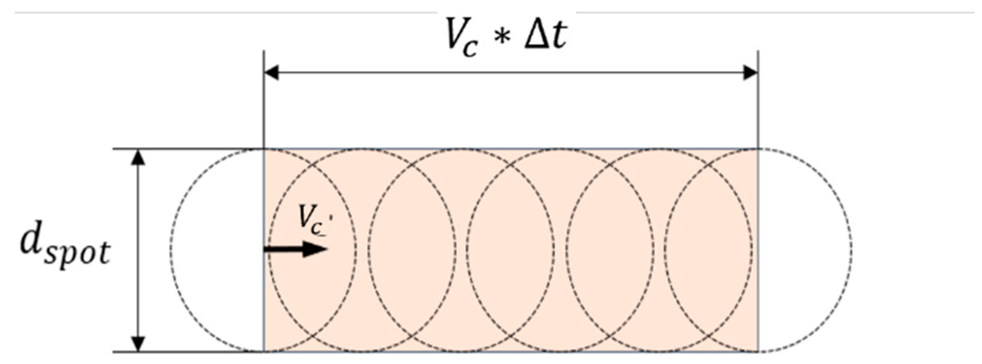
Figure 1. Schematic of pulse overlap.
Jmmp 09 00275 g001
Figure 2. Lithium metal anode sample description.
Jmmp 09 00275 g002
Figure 3. (a) Front view of experimental cutting setup. (b) Laser cutting path of LiM substrates.
Jmmp 09 00275 g003
Figure 4. (a) Representative pulse shapes at base frequency (PRF0) for waveforms WF0 to WF13, showing variations in peak power and pulse duration. (b) Effect of increasing pulse repetition frequency (PRF) on pulse energy and average output power.
Jmmp 09 00275 g004
Figure 5. Laser scanning microscopy images of LiM anode samples classified as (a) No Cut, (b) Partial Cut, and (c) Cut, with annotated quality indicators. (d) Optical microscopy image with average height profile. (e) Three-dimensional reconstruction of cutting edge, and (f) corresponding average height profile of highlighted plane shown in (e).
Jmmp 09 00275 g005
Figure 6. OM and LSM images of laser cuts performed at various scanning speeds with a constant laser power of 200 W, using pulse durations of 261 ns at a pulse frequency of 200 kHz and 72 ns at a pulse frequency of 510 kHz.
Jmmp 09 00275 g006
Figure 7. Pulse shapes for waveform 0 at 261 ns duration under varying PRFs.
Jmmp 09 00275 g007
Figure 8. Laser-cut surfaces at 261 ns pulse duration with varying PRFs.
Jmmp 09 00275 g008
Figure 9. Effect of pulse duration on cut quality at constant line energy and scanning speed. Green frame indicates the parameter window enabling successful cutting.
Jmmp 09 00275 g009
Figure 10. (a) HAZ width, (b) bulge height, and (c) kerf width as functions of pulse duration. Note: x-axes in (ac) are reversed, decreasing left to right. (d) Representative LSM image of cut edge.
Jmmp 09 00275 g010
Table 1. Overview of primary input and secondary process-dependent laser parameters.
Primary Laser ParametersSecondary Laser Parameters
Velocity/ms−1Pulse energy/J
Pulse repetition frequency/HzPulse overlap
Spot diameter/µmIntensity/Wmm−2
Laser power/WLine energy/Jmm−1
Pulse duration/msPulse shape
Disclaimer/Publisher’s Note: The statements, opinions and data contained in all publications are solely those of the individual author(s) and contributor(s) and not of MDPI and/or the editor(s). MDPI and/or the editor(s) disclaim responsibility for any injury to people or property resulting from any ideas, methods, instructions or products referred to in the content.