1. Introduction
Carbon fiber reinforced polymer (CFRP) composites have emerged as critical materials in modern engineering and manufacturing due to their exceptional strength-to-weight ratio, durability, and resistance to corrosion [
1]. These composites are composed of carbon fibers embedded in a polymer matrix, which collectively contribute to a material that is both lightweight and incredibly strong. The unique properties of CFRP composites make it indispensable in sectors where performance and efficiency are paramount. In aerospace, for instance, CFRP composites is utilized extensively to reduce aircraft weight, thereby improving fuel efficiency and reducing emissions [
2]. The automotive industry employs CFRP composites to enhance vehicle performance, safety, and fuel economy [
3]. The construction industry also leverages CFRP composites for its durability and strength, particularly in applications requiring reinforcement and retrofitting of structures [
4]. The widespread use of CFRP across these diverse sectors underscores its versatility and critical role in advancing technological and engineering frontiers.
Applying machining processes to CFRP composites is essential for integrating these advanced materials into practical applications. Machining, particularly drilling, is crucial for creating precise holes and features necessary for assembling components, especially in aerospace and other industries [
5]. However, the machining of CFRP composites presents significant challenges due to their unique material properties. The hardness and abrasiveness of carbon fibers can cause rapid tool wear, while the anisotropic nature of the material often leads to delamination, fiber pull-out, and surface damage [
6,
7]. These issues compromise the structural integrity and performance of the final product. Therefore, improving the drilling process for CFRP is of paramount importance to enhance the efficiency and reliability of manufacturing with these materials.
Ultrasonic assisted drilling (UAD) represents a promising technique for enhancing the machining performance of CFRP composites. By superimposing high-frequency ultrasonic vibrations on the conventional drilling process, UAD can significantly improve the cutting conditions and outcomes [
8]. The ultrasonic vibrations create intermittent cutting, which helps to minimize tool wear and extend tool life [
9]. Additionally, the oscillatory motion aids in more efficient chip removal, reducing the risk of clogging and enhancing surface finish quality [
10]. Shao et al. reported in their study on CFRP/Ti stacks that the use of UAD resulted in a 67.8% reduction in average thrust force compared to conventional drilling (CD) [
11]. Zheng et al. found that when using a brad drill for drilling CFRP composites, the maximum thrust force was reduced by 22.57% and the average thrust force by 14.22% with rotary ultrasonic drilling compared to CD [
12]. Huang et al. reported a 13.0% reduction in the average width of tool flank wear when using UAD for CFRP composite drilling compared to CD [
13]. Feng et al. indicated that UAD in CFRP drilling reduces the overall axial force and decreases the tearing factor, thereby reducing burr formation and hole damage compared to CD [
14]. Consequently, UAD offers a viable solution for overcoming the inherent challenges associated with machining CFRP composites, leading to higher precision, better surface integrity, and increased overall efficiency in the manufacturing process.
Minimum quantity lubrication (MQL) presents an effective alternative for cooling and lubrication when machining CFRP composites, as conventional cutting fluids (CCFs) are often unsuitable for these materials [
15]. MQL involves the application of a fine mist of lubricant directly to the cutting zone, providing adequate cooling and lubrication while using significantly less fluid compared to traditional methods [
16]. Additionally, MQL is environmentally friendly and reduces the health risks associated with exposure to large volumes of cutting fluids [
17]. The reduced fluid usage also leads to cost savings and simplifies the cleanup process [
18].
Nagaraj et al. reported that in CFRP composite drilling, MQL resulted in less deviation in nominal hole size compared to dry conditions when appropriate parameters were maintained [
19]. Xu et al. applied MQL with an internally cooled drill tool in CFRP/Ti6Al4V stacks, achieving a smoother hole surface and observing fewer defects compared to dry conditions. Additionally, MQL reduced the burr height magnitude by 17.81% [
20]. Nagaraj et al. found that applying MQL in CFRP composite drilling led to lower surface roughness values compared to dry conditions. By combining efficient cooling and lubrication with environmental and economic benefits, MQL is a highly suitable and advantageous solution for machining CFRP composites [
21].
Combining UAD and MQL presents a promising approach for improving the drilling performance of CFRP composites. UAD enhances the cutting process by reducing thrust force, minimizing tool wear, and improving surface finish through high-frequency vibrations that facilitate chip removal and reduce delamination risks [
8]. Meanwhile, MQL provides effective lubrication and cooling with minimal fluid usage, which not only reduces environmental impact but also further decreases tool wear and surface roughness by minimizing heat generation and friction. Together, UAD and MQL can address the challenges associated with drilling CFRP by combining the mechanical benefits of vibration assistance with the lubrication and cooling advantages of MQL. Several studies have explored the combination of ultrasonic vibration-assisted machining with MQL. Aminria et al. applied ultrasonic vibration-assisted milling with MQL to CFRP material, finding that the combination resulted in a surface roughness reduction of up to 55% compared to dry, water, and oil cooling/lubrication conditions [
22]. Guo et al. experimented with low-frequency vibration-assisted drilling and MQL on CFRP/Ti6Al4V stacks, noting that variations in the oil–gas mixing ratio affected machining performance [
23]. Wang et al. used ultrasonic vibration helical milling with MQL on CFRP/Ti6Al4V stacks, reporting reductions in cutting temperature and average flank wear compared to dry conditions [
24].
As evidenced in the literature, both UAD and MQL have individually demonstrated significant improvements in the machining of CFRP composites. However, the combination of these two methods has not been thoroughly explored, particularly for standalone CFRP materials. Previous studies that integrate vibration-assisted or ultrasonic methods with MQL have primarily focused on milling operations or hybrid stacks such as CFRP/Ti6Al4V, often employing low-frequency vibrations rather than ultrasonic assistance. To the best of the authors’ knowledge, this study represents the first systematic investigation of UAD and MQL applied simultaneously to the drilling of pure CFRP composites. The aim is to enhance drilling performance through this novel combination and compare it against conventional drilling and dry cutting. The evaluation includes key performance metrics such as cutting forces, hole quality (diameter, cylindricity, and roundness), hole inside surface roughness, and drilling-induced damage (uncut fibers, burrs, and delamination).
2. Materials and Methods
The workpiece used in the study is a CFRP composite formed from unidirectional layers in the shape of a plate. The dimensions of the workpiece are 150 mm × 150 mm × 5.9 mm. The CFRP composite workpiece consists of 32 layers; fiber orientations in the layers forming the workpiece are arranged as [45/135/0
4/90
2/135/0
4/45/90
4/45/0
4/135/90
2/0
4/135/45]. The mechanical properties of CFRP workpiece can be seen in
Table 1.
The drilling experiments were conducted on an Akira-Seiki Preforma SR3 CNC vertical machining center. While the cutting speed was kept constant in all experiments, three different levels of feed rate were tested. The cutting speed and the feed values were recommended by the cutting tool manufacturer. The drilling tool used in the experiments is an EMUGE-FRANKEN (Lauf an der Pegnitz, Bavaria, Germany) brand 7460F model Diamond/ZR coated solid carbide twist drill, specifically manufactured for CFRP drilling [
25]. The geometric properties of the cutting tool are provided in
Table 2. Each test was conducted with a new drilling tool. The tests were performed through holes with a depth of 6 mm. Three holes were drilled for each test, and the average of these three holes was taken to ensure repeatability. The experiments were carried out under two machining conditions, CD and UAD, and each machining condition was tested with two different cooling/lubrication methods, dry and MQL. A total number of 36 drilling experiments were conducted. In the UAD experiments, axial ultrasonic vibrations (along the
Z-axis) were applied to the drilling tool using a BT40 type Altrasonic (Hangzhou, China) brand ultrasonic tool holder integrated with a closed-loop control ultrasonic generator [
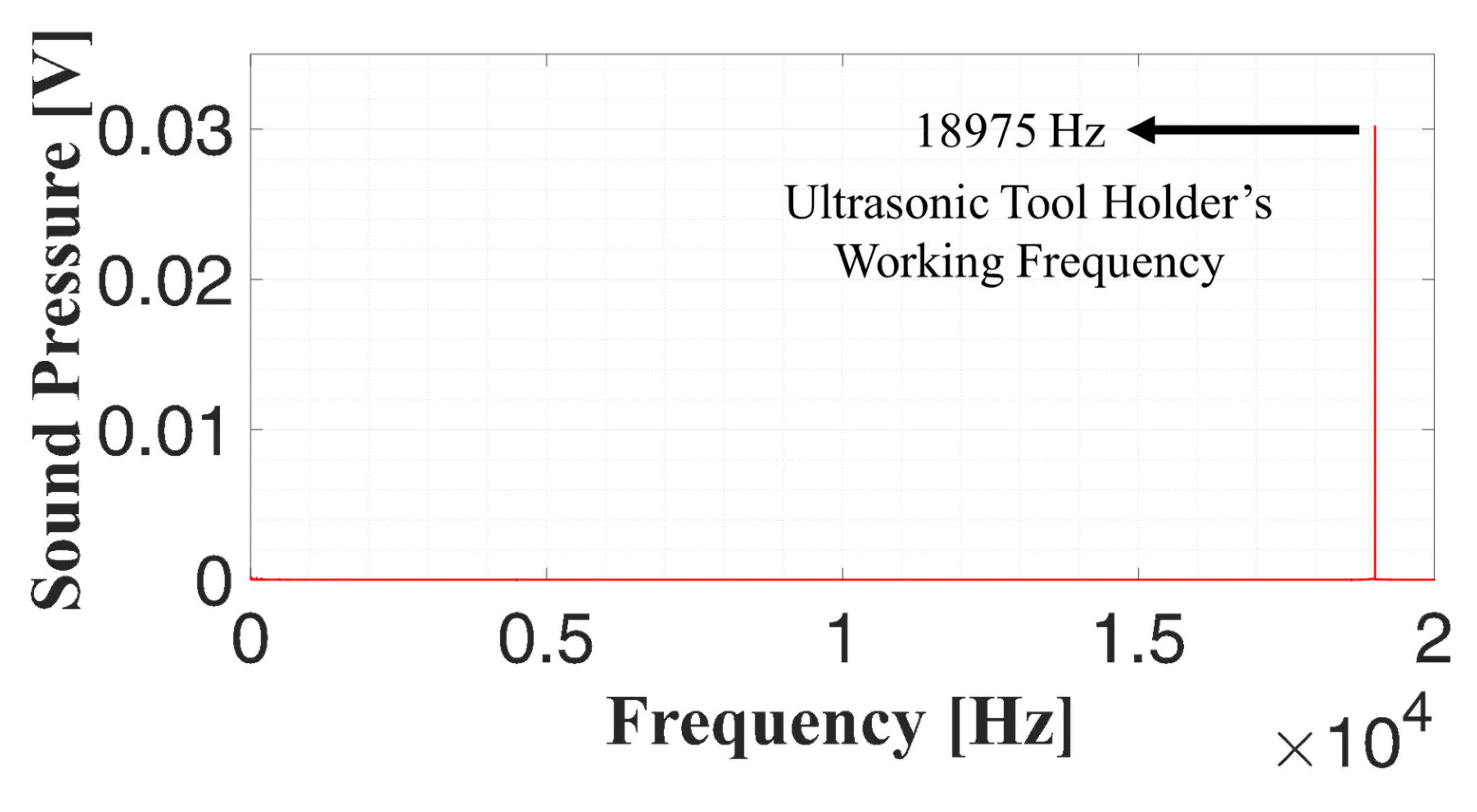
26]. This system automatically adjusts and maintains the vibration frequency at the resonant frequency of the combined setup, considering factors such as the attached cutting tool. As a result, the applied ultrasonic vibration frequency was determined to be 18,975 Hz, with an amplitude of 6 µm. The resonance-based nature of the system ensures optimal energy transfer and vibration stability. The applied frequency was verified through fast Fourier transform (FFT) analysis of the sound signals collected from the ultrasonic tool holder, as shown in
Figure 1.
The CD tests were conducted without ultrasonic vibrations using the same ultrasonic tool holder to achieve identical conditions. The MQL tests were conducted using a commercially available Bielomatik (Neuffen, Germany) brand B1-210 coded MQL unit. Ester-based Vascomill CSF 35 was used as the MQL oil. The properties of the MQL oil are provided in
Table 3. The MQL aerosol was sprayed into the cutting zone at a 45° angle from a distance of 100 mm, using an external nozzle with a 5 mm diameter. The system operated at a pressure of 6 bar and a flow rate of 150 mL/h. These parameters were selected based on the authors’ previous ultrasonic-assisted milling studies [
27,
28], where similar pressure and spray angle yielded effective results. However, a higher flow rate was adopted in this drilling study to ensure adequate lubricant penetration into the hole, addressing the geometric constraints of the drilling process. During the experiments, cutting force measurements were taken with a Kistler 9265B three-component piezoelectric quartz crystal dynamometer, and the collected cutting forces were measured and analyzed using Dynoware (Version 3.3.1.0) and Matlab (Version R2022b) software. In order to accurately measure the effects of ultrasonic vibrations, cutting force measurements were taken at a sampling rate of 100 kHz. During the drilling operation, the mean thrust force in the region where drill lips are fully immersed in the workpiece was determined. After the drilling experiments, a Hexagon Global Classic coordinate measuring machine (CMM) was used to assess the geometric quality of the drilled holes. The measurements focused on key dimensional accuracy parameters, including diameter error, cylindricity, and roundness, to evaluate the effects of the different drilling conditions. Cylindricity measurements were performed by dividing each hole into three regions: entry, middle, and exit. In each region, seven equally spaced measurement points were taken along the inner hole surface using the CMM. The local cylindricity values obtained from each region were averaged to compute a representative cylindricity value for the entire hole. Similarly, roundness and diameter measurements were conducted at both the entry and exit of each hole using CMM-captured circular cross-sections. Cylindricity was measured according to ISO 12180-1 [
29], and roundness according to ISO 12181-1 [
30]. The surface roughness values inside the holes were measured with a Mahr (Goettingen, Germany) brand MarSurf PS1 surface roughness measurement device. The average of the three measurements taken from each hole was used to determine the Ra value. A ZEISS Stemi 305 stereo microscope was used for measuring the hole damage. The design of experiments can be seen in
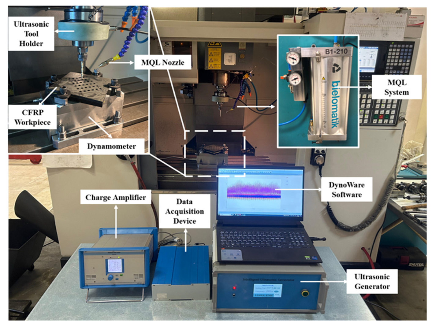
Table 4, while the general experimental setup can be seen in
Figure 2.
3. Results
3.1. Thrust Force Results
Thrust force, which is the axial (
Z-axis) cutting force component in drilling operations, is a crucial performance output that directly impacts process stability, energy consumption, and hole quality.
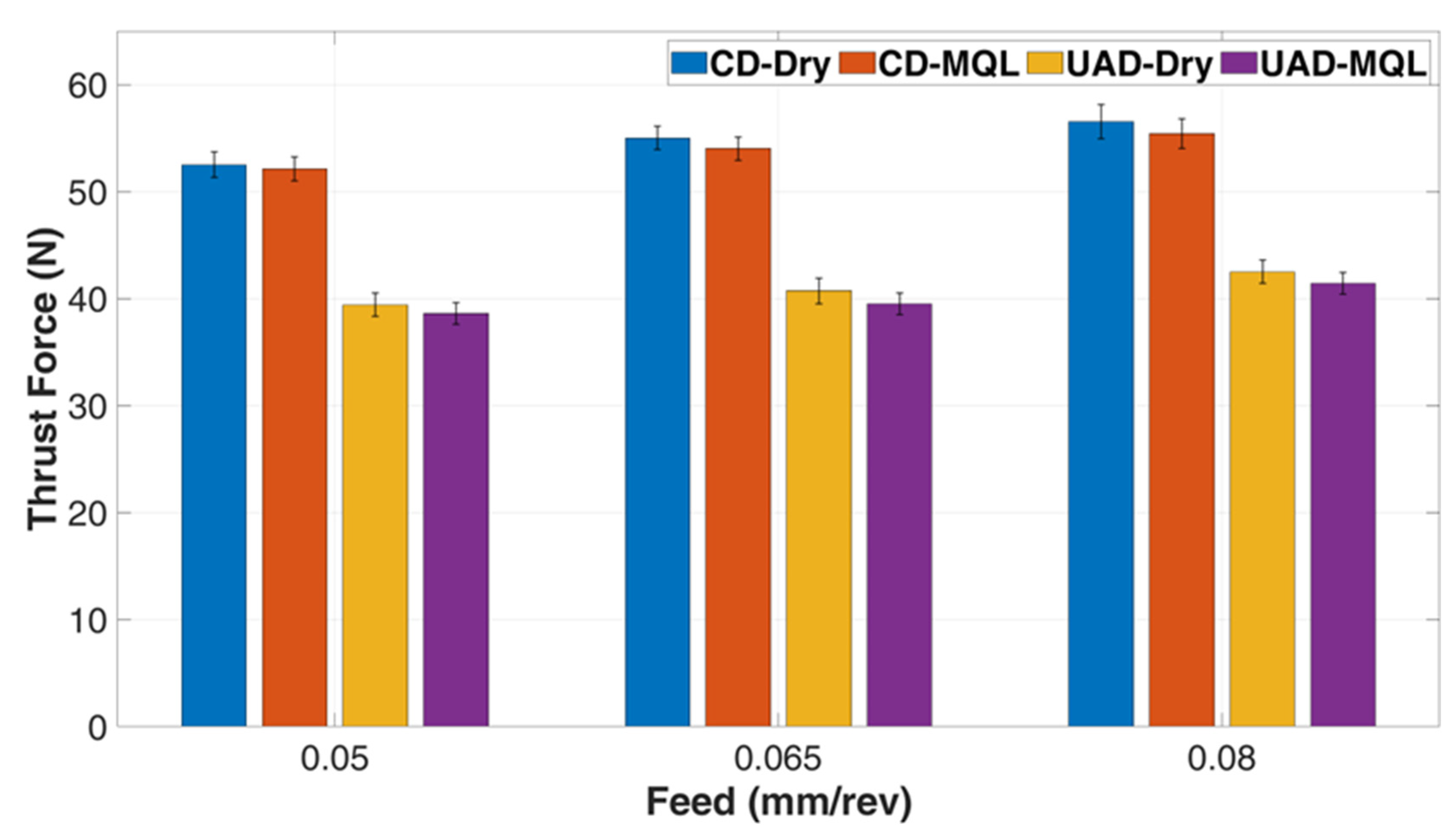
Figure 3 presents the thrust force values obtained from the experiments. According to the results, UAD consistently produced lower thrust force values compared to CD. Specifically, UAD reduced thrust forces by approximately 25–26% under dry conditions and 25–27% under MQL conditions. This reduction is primarily attributed to the axial ultrasonic vibrations applied to the drilling tool, which introduce an intermittent cutting mechanism.
In CD, the tool follows a continuous helical trajectory along the feed direction. This results in continuous contact between the tool and workpiece, which increases friction, heat generation, and the risk of tool clogging—especially in layered composite materials. In contrast, UAD modifies the tool motion by adding high-frequency axial vibrations. This superimposed vibration introduces an intermittent cutting action, where the tool briefly disengages from the material during each vibration cycle. The intermittent nature reduces the effective contact time, which in turn lowers average friction and facilitates chip evacuation. Moreover, the impact-like interaction of the tool with the fiber layers facilitates easier penetration through the stacked plies, minimizing resistance. These combined effects result in a notable reduction in thrust force.
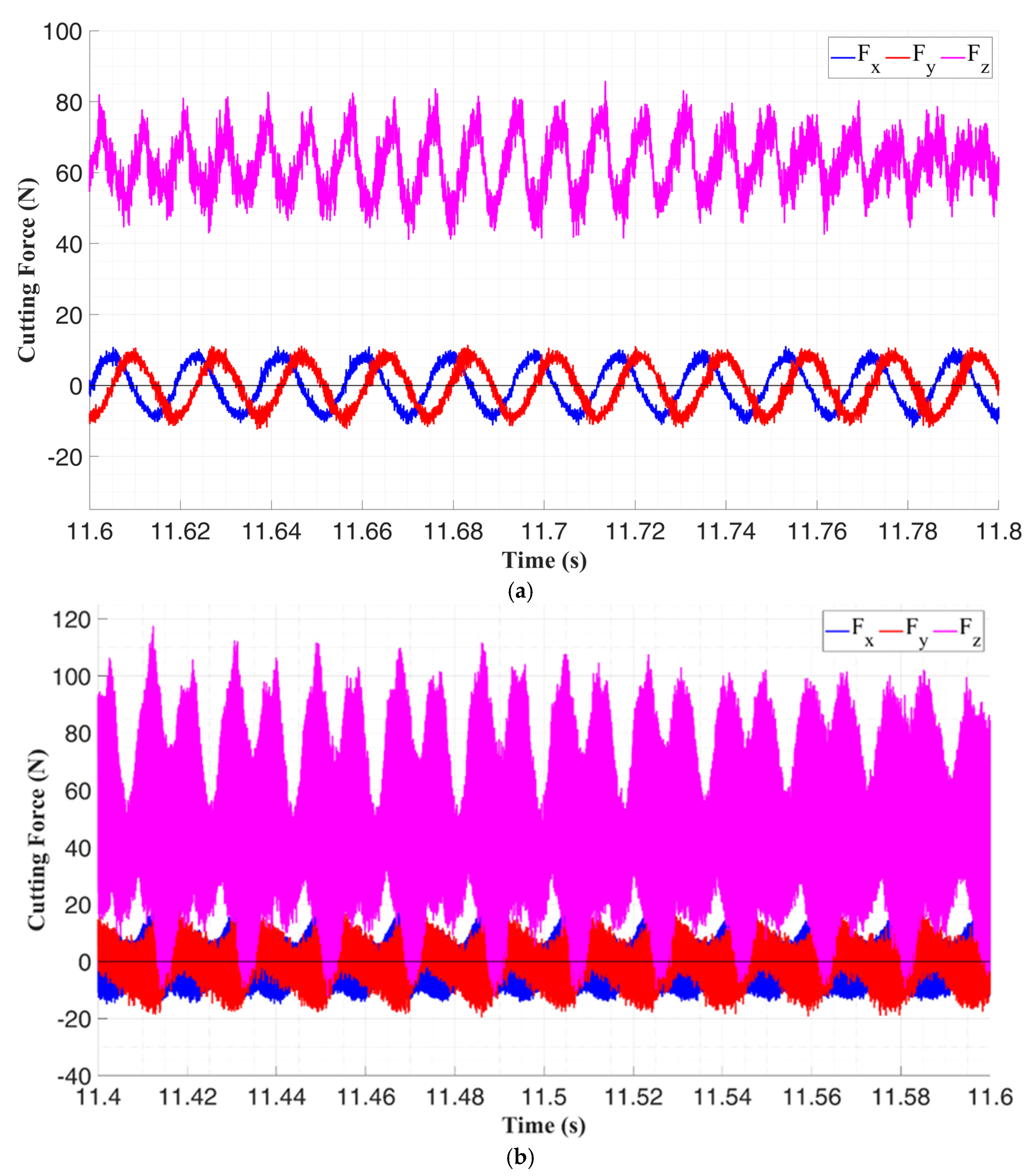
Figure 4 supports this explanation, showing that the
Z-axis cutting force signals during UAD are modulated and lower in magnitude compared to CD. The periodic oscillations in the force signal correspond to the ultrasonic vibrations, further validating the reduced and more stable thrust force behavior under UAD. The more successful results achieved by using UAD in combination with MQL are explained in detail in
Appendix A.
During UAD, axial ultrasonic vibration applied to the cutting tool significantly influence the drilling process and its outcomes. Analyzing these vibrations in the frequency domain provides valuable insight into their effects.
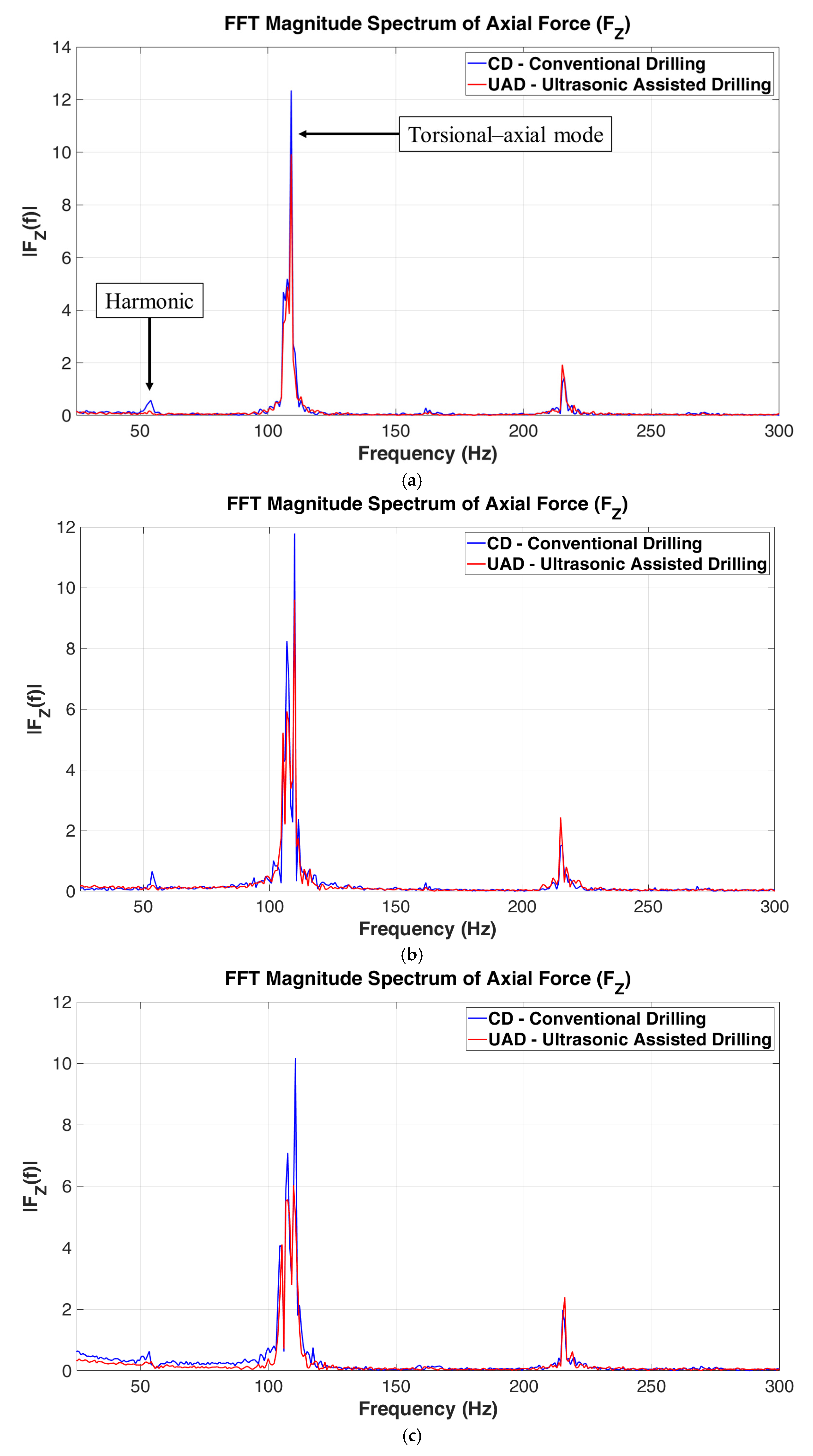
Figure 5 presents the FFT results of the cutting forces for both UAD and CD. The analysis of the Z-direction force component—which corresponds to the thrust force—shows the first harmonic frequency around 54 Hz, which aligns with the spindle rotation frequency (SRF). In the frequency range of 100–120 Hz, both UAD and CD exhibit a distinct component which is close to second harmonic frequency. However, this component is likely associated with torsional–axial vibration. Because, as seen in
Figure 4, this high amplitude vibration is only observed in Z direction, and it has no effect on either X or Y directions. Although identification of this component being resonant or chatter vibration is not scope of this study, the presence of this high amplitude frequency component explains the oscillations observed in the Z-direction force signals shown in
Figure 4. Notably, while the high amplitude vibration is observed in both conditions, UAD resulted in much less amplitude compared with CD. This finding aligns with previous studies suggesting that ultrasonic vibrations can help suppress chatter [
31] in machining due to disturbing the delay component.
When comparing cooling conditions, the experiments with MQL showed slightly lower thrust force values compared to dry conditions. Under CD conditions, MQL resulted in approximately 3% lower thrust force, while under UAD conditions, this reduction was found to be around 4%. Although MQL provides effective cooling and lubrication through pressurized aerosol, its application via external nozzles means that the cooling effect diminishes as the drill bit penetrates deeper into the material.
Regarding the impact of cutting parameters, an increase in feed rate was observed to correspond with an increase in thrust force. This is because a higher feed rate causes the drill bit to remove more material per unit time, requiring greater force to cut through the larger volume of material, thus leading to an increase in thrust force.
3.2. Surface Roughness
The surface roughness of a drilled hole significantly impacts the performance and functionality of the assembled components. For example, smoother surfaces generally allow for better fitting of parts, improved sealing, and reduced friction, all of which are crucial in applications requiring precision and tight tolerances.
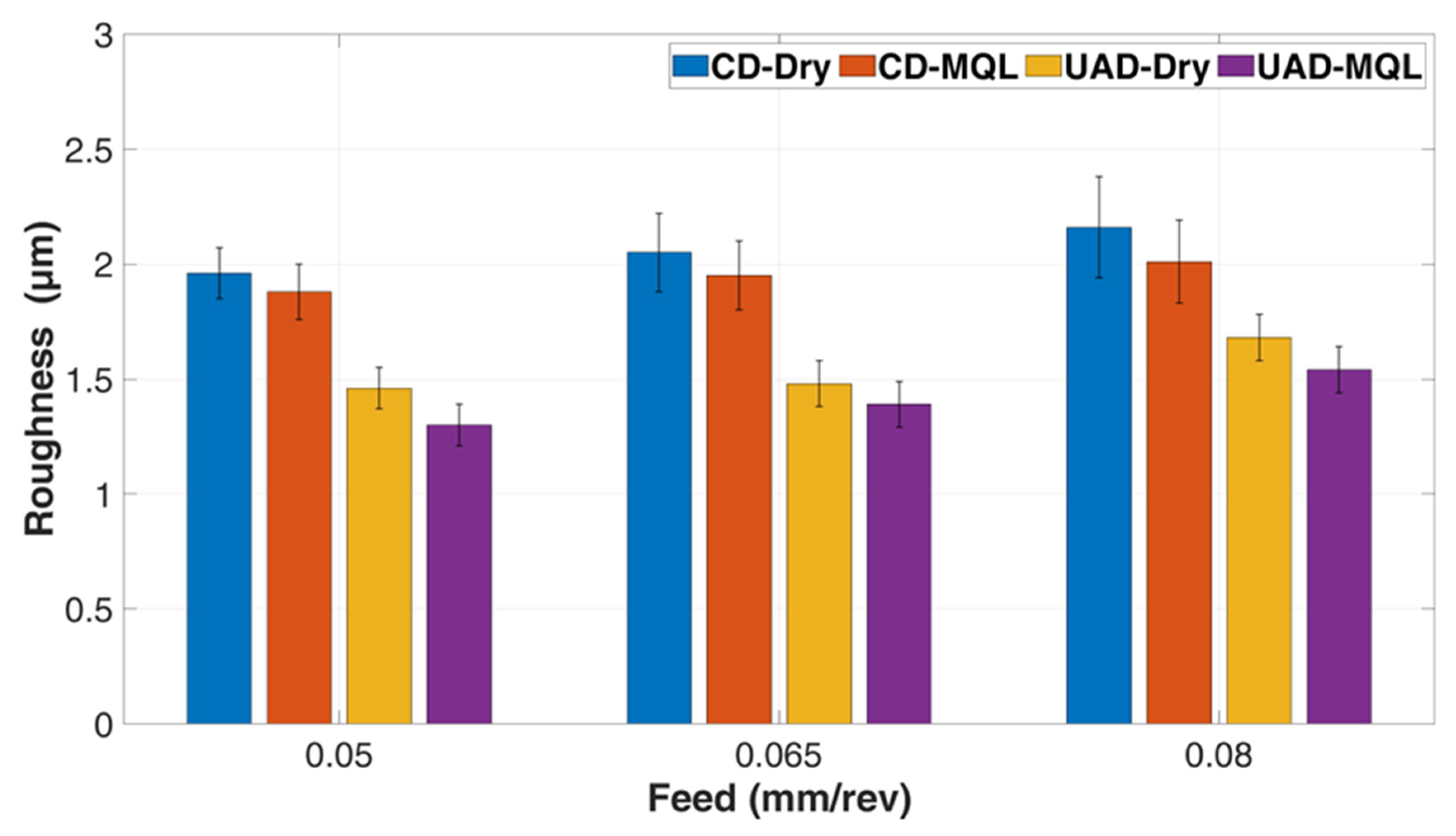
Figure 6 shows the measured inside hole wall surface roughness values from the experiments. The results indicate that UAD produces lower surface roughness compared to CD. The reductions in surface roughness were found to be between 14% and 28% under dry conditions, and between 23% and 31% under MQL conditions. In UAD, the intermittent cutting mechanism created by ultrasonic vibrations helps to efficiently evacuate composite chips/dusts during drilling. Additionally, the reduced thrust force leads to a more stable drilling operation and less tool wear, resulting in lower surface roughness.
MQL also produced lower surface roughness values compared to dry conditions, with reductions ranging from 3% to 5% in CD and from 6% to 11% in UAD. The improvement in surface roughness with MQL can be attributed to its cooling ability, which reduces heat generation. The greater reduction observed with the UAD-MQL combination can be explained by MQL’s high-pressure spraying, which effectively removes composite chips/dusts from the drilled hole, preventing abrasive damage to the hole surface.
Another finding is that with the increased feed rate, surface roughness values also increased. A higher feed rate means the drill bit advances more into the material with each revolution, leading to larger chips/dusts and a more aggressive cutting action. The cutting edge of the drill has to remove more material per unit of time, which can cause irregularities in the surface finish and increase roughness. Additionally, at higher feed rates, chips/dusts form more rapidly, and chip evacuation may become less efficient. Poor evacuation can cause composite dusts to rub against the freshly cut surface which increases surface roughness.
3.3. Hole Diameter Results
Achieving the desired nominal hole diameter after drilling is critical for proper part assembly. Holes that are wider or narrower than the expected nominal diameter can lead to issues such as loose connections, misalignment, or difficulty in assembly. The measured entrance hole diameters after the experiments are shown in
Figure 7a, and the exit hole diameters are shown in
Figure 7b. The data indicate that entrance hole diameters are generally larger and have a higher margin of error compared to exit hole diameters. This is because, at the start of drilling, the tool can wander before fully entering the material, leading to greater deviation. By the time the tool exits, it is more stable inside the material, reducing the error in the exit hole diameter. When comparing UAD and CD, UAD produces hole diameters closer to the nominal size. As seen in the lower thrust force and surface roughness results, the ultrasonic vibrations created by UAD reduce tool deflection, resulting in a more stable drilling process. This increased stability helps the drill bit maintain a more consistent cutting path.
Regarding cooling and lubrication conditions, MQL provides hole diameters closer to the nominal size compared to dry conditions. The effective lubrication and cooling provided by MQL result in less heat generation, which contributes to a more precise hole diameter. An interesting finding is that the effect of MQL is less pronounced on exit hole diameters. This is likely because MQL, applied through external nozzles, may not provide sufficient cooling as the drill bit goes deeper. Another important observation is that increasing the feed rate leads to a greater deviation from the nominal diameter. Higher feed rates result in a higher material removal rate, which puts more load on the drilling tool and can cause inconsistencies in the hole diameter.
3.4. Hole Roundness Results
Hole roundness is a critical performance measure for mechanical integrity in assemblies. A round hole ensures even load distribution around its circumference. Irregularities in roundness can lead to uneven stress distribution, which may cause early failure. It is also important for sealing; deviations in roundness can result in leaks, reducing the product’s performance. The measured roundness errors for the entrance holes are shown in
Figure 8a, and for the exit holes in
Figure 8b. The data show that, similar to hole diameter measurements, the exit roundness errors are lower than the entrance roundness errors. This is because, during the initial tool engagement, the tool is less stable, which can cause deflection and misalignment. As drilling progresses and the tool becomes better aligned within the material, the roundness errors at the exit decrease.
In the experiments where UAD was applied, it was observed that roundness errors were lower compared to CD. Under dry conditions, the reduction in entrance hole roundness ranged from 30% to 36%, while the reduction in exit hole roundness ranged from 33% to 36%. In MQL conditions, UAD showed a reduction in roundness error compared to CD, with decreases of 27% to 31% in entrance hole roundness and 38% to 41% in exit hole roundness. The lower cutting forces observed with UAD, which parallel its reduced hole diameter errors, help minimize issues like tool deflection, leading to more accurate roundness values.
It has been observed that cooling and lubrication conditions also affect roundness error. MQL resulted in lower roundness errors compared to dry conditions. In CD, MQL showed a reduction in entrance hole roundness error by 15% to 24%, and a reduction in exit hole roundness error by 5% to 10% compared to dry conditions. In UAD, the reduction rates between MQL to dry were found to be between 14% and 18% for entrance hole roundness and between 14% and 16% for exit hole roundness. Another observation is that MQL’s effect is more pronounced on entrance hole roundness than on exit hole roundness. This can be explained by the fact that, as noted in the hole diameter results, since MQL was applied through an external nozzle, the advantages of the cooling and lubrication effect of MQL diminishes as the drill bit progresses through the hole and becomes less effective to the cutting zone where the drill bit contacts the CFRP workpiece.
It was also observed that as feed rate increases, roundness errors increase, independent of all other parameters. This can be attributed to the increased load on the drilling tool and higher chip load due to the need to remove more material in a shorter time. Consequently, the tool’s stability is negatively impacted, leading to deviations from the desired roundness.
3.5. Cylindricity Results
Cylindricity is an important factor that directly affects hole quality. It not only indicates whether a hole is round but also shows how consistent its diameter is along the entire length. This consistency is crucial for proper assembly, preventing leaks, and minimizing wear between mating parts. The cylindricity results can be seen in
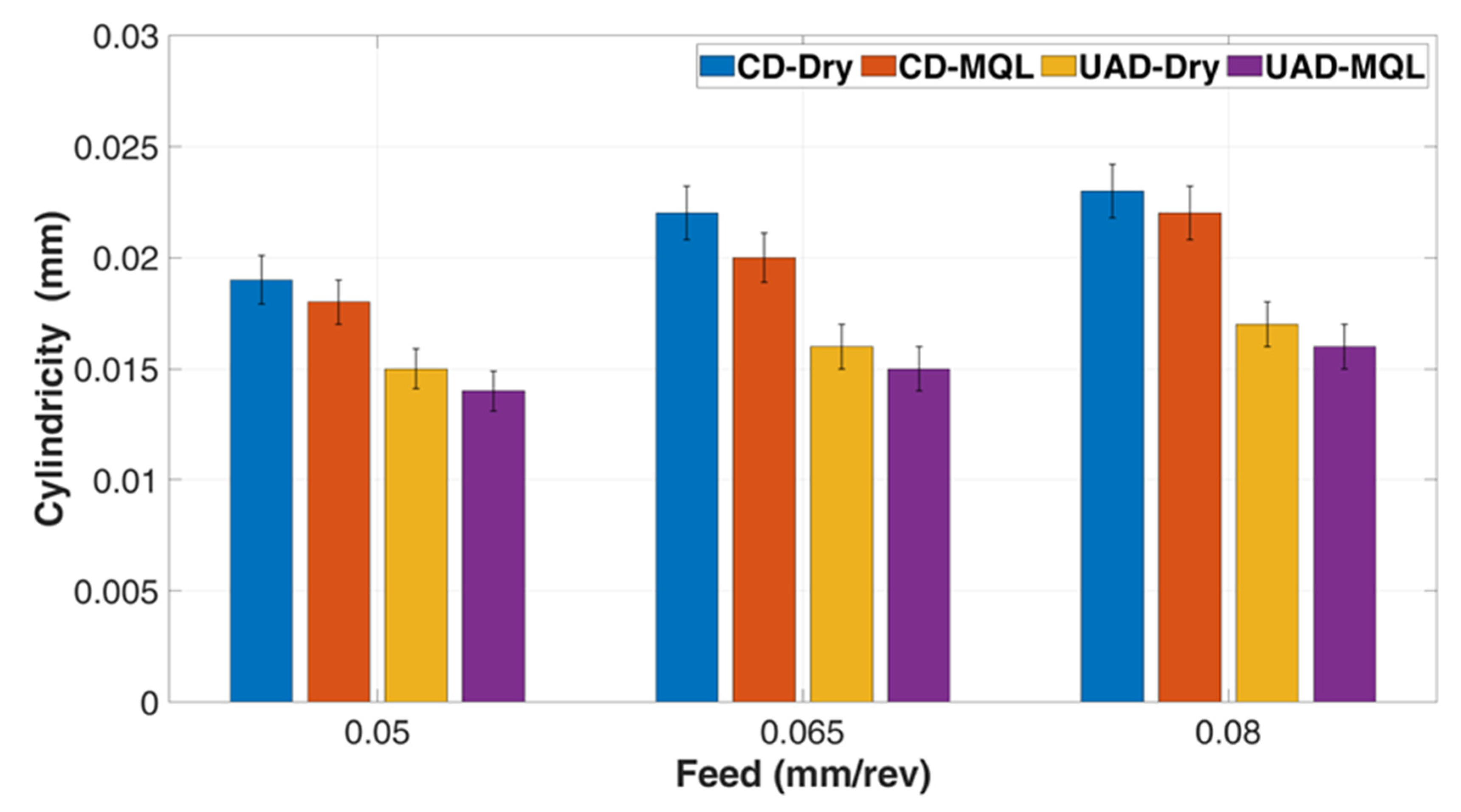
Figure 9. When comparing machining conditions, UAD produces better cylindricity than CD. Under dry conditions, UAD achieved cylindricity improvements of 33% to 36% compared to CD, and under MQL conditions, UAD improved cylindricity by 38% to 41%. CFRP composites are challenging to cut because of its abrasive and layered nature, but UAD reduces tool deflection, keeping the tool aligned and creating a more cylindrical hole. UAD enhances chip/dust removal, maintaining a consistent hole shape since effective chip/dust removal is vital in drilling, as poor evacuation can lead to overheating and wear, making the hole less uniform. CFRP is also prone to delamination and fiber pullout, but UAD’s controlled cutting action minimizes these issues, ensuring the hole stays closer to the desired cylindrical shape.
MQL also results in lower cylindricity errors compared to dry conditions. With MQL, cylindricity is reduced by 5% to 9% compared to dry conditions and by 14% to 16% compared to UAD. MQL cools and lubricates the drill bit, which reduces heat and friction. This helps maintain tool stability and prevents rapid wear, crucial for keeping a consistent cylindrical shape. MQL also improves chip/dust removal, reducing clogging and overheating that can distort the hole. Overall, MQL contributes to more accurate and cylindrical holes in CFRP compared to dry drilling.
Additionally, higher feed rates in CFRP drilling often lead to increased cylindricity errors. The greater force exerted at higher feed rates can cause the drill bit to wobble or vibrate, accelerating tool wear and causing chip/dust buildup that clogs the cutting area. This leads to uneven material removal and more heat, which can soften the CFRP and distort the hole. These factors all contribute to less accurate cylindrical holes.
3.6. Delamination Results
During the drilling of CFRP composites, delamination is a critical issue that affects the structural integrity and performance of composite materials. CFRP consists of layers of carbon fibers embedded in a polymer matrix. However, the interaction between the rotating drill bit and the composite material during the drilling process can lead to separation or damage in the form of layer delamination, where the fiber layers and the polymer matrix separate or are damaged. Delamination is particularly common at the entry and exit points of the drill due to sudden changes in cutting conditions. As the drill penetrates the composite material, it encounters varying levels of resistance, leading to stress concentrations that can initiate and propagate delamination. Similarly, as the drill exits the material, different exit conditions can cause further damage. Delamination negatively affects the mechanical properties and load-bearing capacity of CFRP structures. It weakens the material and reduces its fatigue life, potentially leading to premature failure. Minimizing delamination is crucial in applications where the structural integrity of CFRP components is critical, such as in the aerospace and automotive industries.
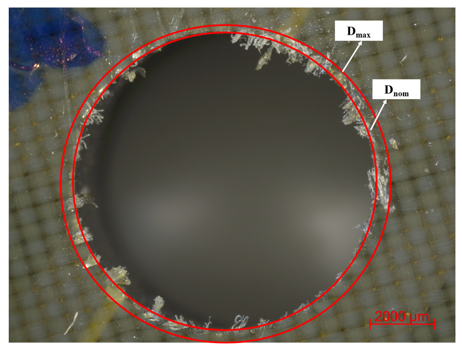
In this study, delamination measurements were conducted using an optical microscope, and the delamination factors were determined by transferring the images captured in the microscope to an image analysis software.
Figure 10 shows a sample image of delamination factor calculation used in this study. The delamination factor was calculated as the ratio of the maximum diameter in the deformed region to the drill diameter, as described in Equation (1) [
32], where
is the maximum damaged diameter and
is the hole diameter.
Figure 11 presents the delamination factor results obtained from the experiments. The findings indicate that feed rate significantly influences delamination. As the feed rate increases, the delamination factor also rises. This trend is observed consistently across all drilling and cooling method combinations. The increase in feed rate generates higher forces on the material, resulting in more pronounced separation of the laminate layers. Furthermore, a comparison between CD and UAD demonstrates that UAD consistently achieves lower delamination factors under equivalent conditions. The application of ultrasonic vibrations in UAD reduces the thrust force and, consequently, the mechanical stress on the laminate, thereby mitigating delamination. The choice of cooling technique also affects delamination. The data show that MQL leads to a slight reduction in the delamination factor compared to dry drilling. This effect becomes more significant at higher feed rates and when combined with UAD, suggesting that MQL is particularly effective when used in conjunction with ultrasonic assistance.
In conclusion, the results of delamination factor indicate that both feed rate and drilling method play a critical role in minimizing delamination during drilling operations. Lower feed rates reduce the mechanical load on the material, while UAD offers a more advanced approach to further minimize delamination by decreasing mechanical stress. Although cooling strategies such as MQL contribute to delamination reduction, their influence is secondary compared to that of feed rate and drilling technique.
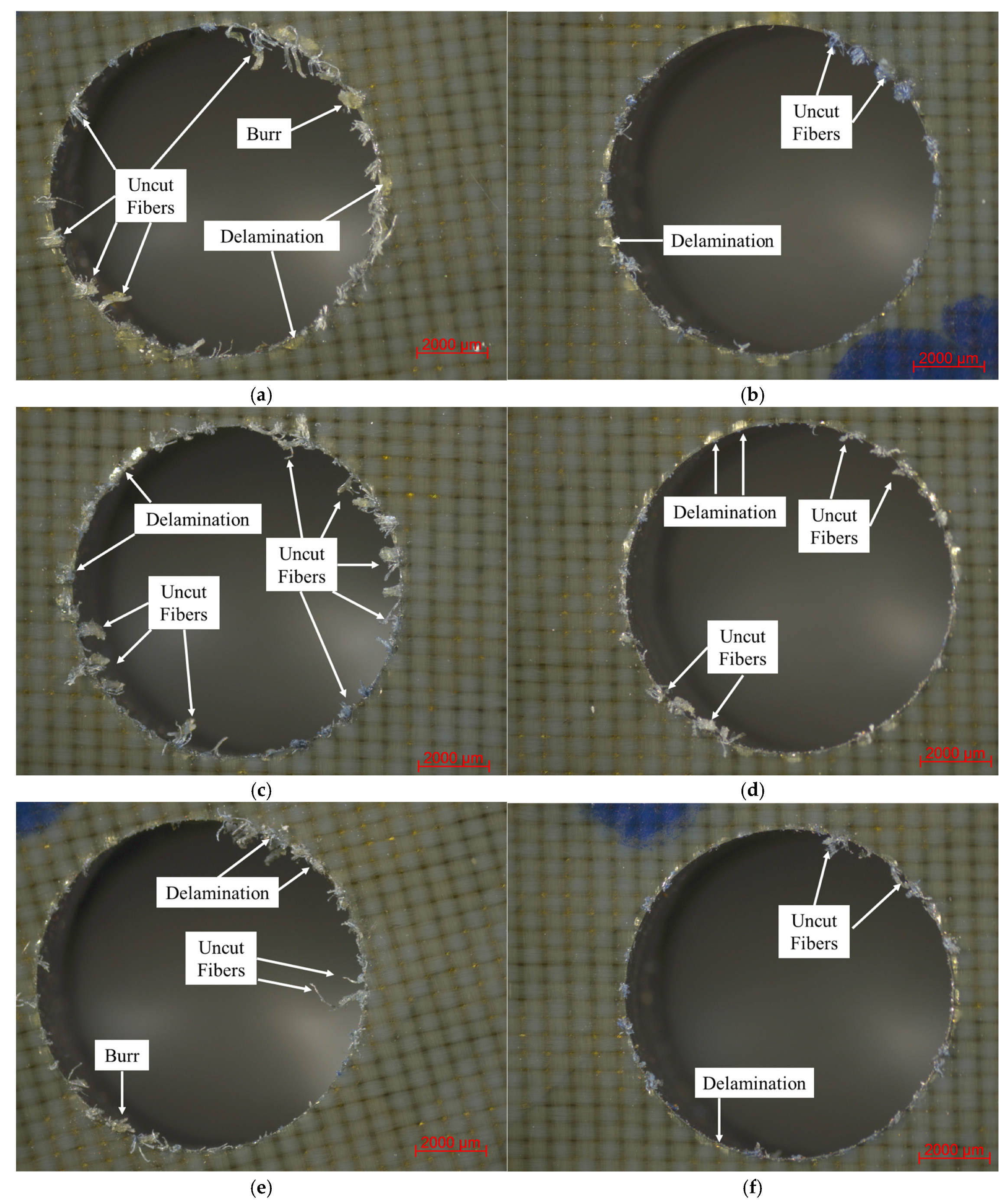
Delamination is often regarded as the primary concern when drilling composite materials due to its potential to compromise structural integrity. However, other types of damage can also occur and have similarly detrimental effects. These include uncut fibers, fiber pull-out, and burr formation, all of which degrade the quality of the drilled surface and the overall performance of the composite. These defects were observed in this study using optical microscopy, and representative images are provided below.
Figure 12 presents a comparative analysis of drilling-induced defects observed under CD and UAD conditions. The images and inspection results reveal that the holes produced using UAD exhibit a markedly superior hole quality. Specifically, the peripheries of UAD-drilled holes are smoother, with significantly fewer uncut fibers, minimal burr formation, and reduced signs of fiber fraying or delamination. In contrast, holes generated by CD show more severe and widespread damage, including extensive fiber pull-out, larger and more irregular burrs at both entry and exit sides, and visible signs of partial delamination along the hole edges. These differences highlight the pronounced influence of ultrasonic vibrations on the dynamics of composite drilling. In UAD, the superimposed high-frequency axial oscillations introduce an intermittent cutting action that fundamentally alters the tool–material interaction. This vibration-induced separation between the tool and workpiece—occurring at microsecond timescales—reduces the average thrust force on the cutting tool. As a result, the cutting engagement becomes more stable and less aggressive, which in turn lowers the mechanical and thermal stresses transmitted to the composite structure.
The reduction in uncut fibers observed with UAD is particularly noteworthy. Uncut or poorly sheared fibers are a common issue in composite machining due to the inhomogeneous and anisotropic nature of fiber-matrix architectures. Their presence not only degrades hole quality but also compromises the dimensional accuracy and fatigue performance of the component. The improved fiber severing observed with UAD suggests a more efficient chip formation process and enhanced cutting-edge penetration through the composite layers. This improvement is likely facilitated by the vibration-induced microcracking and softening at the tool–fiber interface, which aids material removal and reduces tool clogging. Furthermore, the minimization of typical defects—such as delamination, burrs, and fiber breakout—under UAD directly contributes to better hole integrity and dimensional stability. This is critical for load-bearing or fatigue-sensitive applications, particularly in aerospace structures, where tight tolerances and damage-free holes are essential for long-term durability and performance. By enabling cleaner cuts with reduced subsurface damage, UAD offers not only surface integrity improvements but also potential gains in mechanical reliability at the structural level.
