Abstract
In 3D printing, the layered structure often results in artifacts. This effect becomes stronger for surfaces with a lower ramp angle. This effect can be mitigated by manufacturing parts with non-planar layers that fit the parts’ surface geometry. Using the open-source slicing software PrusaSlicer. an algorithm was developed to modify the slicer’s input and output data in a way that fits parts with low ramp angle surfaces. To achieve consistent part quality, all layers were modified to be printed in a non-planar way. The test results indicate that the proposed methods can significantly reduce surface roughness. Although the algorithm works well for parts with a flat base and vertical walls, it would need to be highly adapted to work for different part geometries. Additionally, compared to other algorithms used in Curved-Layer Fused Deposition Modeling (CLFDM), the changed layer structure introduces a changed visual appearance of parts.
1. Introduction
Additive manufacturing technologies have become increasingly important in recent years. In contrast to traditional subtracting manufacturing technologies, these technologies offer several advantages, the most significant ones being increased design flexibility, reduced material waste, and the elimination of any additional casts or dies that need to be manufactured for each newly produced part [1].
The most important additive manufacturing technique is layered manufacturing, often called 3D printing. In this technology, the 3D model is first digitally divided into multiple horizontal layers in a process known as slicing. These layers are then sequentially deposited or fused together, one on top of another, to form the final 3D object. A variety of methods are utilized to apply these layers. Among these methods, fused deposition modeling (FDM) is one of the most widely employed, wherein thermoplastics (e.g., PLA, ABS, and PET) are melted and deposited. A single layer is created by depositing the molten plastic in a pattern calculated during the slicing process [2,3].
The surface of parts manufactured by the means of FDM thus typically shows artifacts generated by the slicing process, as seen in Figure 1a. This effect is particularly observed on surfaces with slight inclinations, as seen in Figure 1b. In these scenarios, the effect is referred to as the stair-stepping effect [4] and negatively influences a part’s surface roughness and visual quality. The layer height can be lowered to reduce the negative influence of the stair-stepping effect on the surface. However, reducing layer height increases production time [5]. The layer height is thus normally limited to a minimum of around 0.05–0.1 to achieve acceptable manufacturing times and also due to the accuracy and resolution of typical hardware.
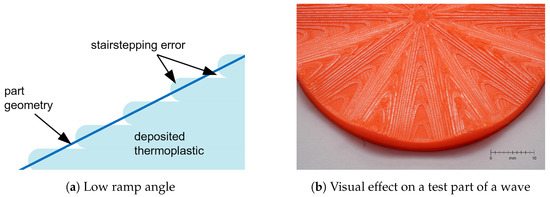
Figure 1.
Stair-stepping effect.
Previous studies have identified the negative impact of the stair-stepping effect on mechanical properties, with some specifically examining its relationship to surface defects and porosity in printed parts [6,7,8]. Several post-processing methods, including chemical treatments, thermal processing, and laser-based techniques, have been proposed to mitigate surface defects and reduce porosity.
Various approaches in slicing and printing strategies can be used to reduce the stair-stepping effect. Conventional methods include adaptive slicing, where the layer height varies throughout an object. The layer height is adaptively decreased for intricate parts of the object and is increased for non-critical parts. Wang et al. [9] performed a comparative analysis of different approaches to this method. Part rotation is another method aimed at minimizing stair-stepping [10]. While these methods help mitigate the staircase effect, they cannot fully eliminate it.
Chakraborty et al. [11] proposed a dedicated slicing algorithm for a different approach called Curved-Layer Fused Deposition modeling (CLFDM). This approach uses non-planar, parallel layers that conform to the shape of the part’s outermost surface that are offset to fill the part geometry. While this approach eliminates stair-stepping artifacts, it is designed only to process shell-type parts. The approach proposed by Ahlers [4] combines conventional planar slicing for inner layers with non-planar slicing for the uppermost layers. This algorithm was implemented in the open-source software Slic3r, representing one of the first non-planar algorithms to achieve widespread implementation. While this approach significantly extends the geometries that can be processed, it relies on a complex algorithm to categorize planar and non-planar parts of a geometry. Shan et al. [12] introduced a method that utilizes isothermal surfaces in heat transfer simulations to generate non-planar surfaces. Feng et al. [13] demonstrated the implementation of non-planar printing using five-axis printers. This further expands the possibilities and advantages of non-planar printing. The publication by Nayyeri et al. [14] offers a comprehensive overview of the current status of both planar and non-planar slicing algorithms for fused deposition modeling technology. In addition, the advantages and disadvantages of these approaches are considered in detail, and the impact of the slicing strategy on various parameters such as surface quality, build time, support structure, and mechanical properties are discussed.
Nayyeri et al. [14] describe non-planar slicing methods as advanced techniques that enable the generation of out-of-plane slices for 3D models. They further state that these methods often require specialized multi-axis hardware upgrades and involve complex computations. These computational demands remain significant, even when constrained to the standard Cartesian kinematics applied in this work. Current non-planar slicing solutions in the literature typically rely on custom software tailored to specific cases, such as Ahlers et al.’s [4] non-planar slicing functions built into a modified version of Slic3r. While effective for limited applications, such custom solutions necessitate ongoing maintenance and lack the extensive, empirically validated optimizations available in standard slicers like PrusaSlicer [15] or Cura [16].
In contrast, the approach presented here introduces two novel methods to achieve non-planar slicing within the framework of an advanced, mainstream slicer, eliminating the necessity for a dedicated, custom-built non-planar slicer. Both methods transform the .stl file, apply conventional planar-slicing software, and subsequently modify the generated GCode to convert planar-sliced paths into non-planar paths. A similar concept is seen in Wüthrich et al. [17], where this approach reduces support material requirements.
Based on our review of existing literature, no existing non-planar slicing techniques leverage standard, widely used slicers. Our method uniquely enables non-planar capabilities within a mainstream slicer by retaining a key property of planar slicing—collision-free paths—thus simplifying implementation and potentially enhancing the processing efficiency.
This study aims to develop and evaluate two novel algorithms that enable the fabrication of parts with non-planar layers tailored to their surface geometry, with a particular focus on surfaces with low ramp angles. The primary objectives are to enhance visual appearance, reduce surface roughness through non-planar printing techniques, and ensure consistent part quality by adapting all layers for non-planar printing.
2. Methods
A Python-based program was developed to automate the steps required for our non-planar slicing approach. First, the non-planar surface is recognized, then the STL file is transformed, the PrusaSlicer is executed in the background, and the resulting GCode is transformed. The open-source code is available on GitHub [18].
These methods achieve a uniform component quality with a smooth surface and a reasonable computing time (Section 3.1). However, it is currently limited in its ability to recognize and address more complex surface features, such as offsets.
2.1. Detection of Non-Planar Surfaces
Both proposed methods transform a given part depending on its surface geometry. Various approaches can be used to obtain surface data for further computations. Chakraborty et al. [11] and Jin et al. [19] used parametric curved surfaces that are offset to fill the part. Huang and Singamneni [20], as well as Singamneni et al. [21], utilized STL data to generate the surface points required. They explain that the use of STL files offers a more fundamental approach, providing greater flexibility by eliminating the need for commercial CAD software and associated standardization. Additionally, STL files can be modified and optimized through mesh refinement techniques, which is crucial for accurately identifying the top surfaces of objects with complex shapes. Despite the drawbacks of using STL data, such as tessellation errors and the generally low resolution of the point cloud, it remains the preferred format due to its widespread use as the standard for Fused Deposition Modeling (FDM).
2.1.1. Physical Manufacturability
The physical manufacturability must be considered a limiting factor when printing non-planar layers. Most common machines used for 3D printing use either a 3-DOF gantry architecture or a 3-DOF linear delta architecture. Due to this architecture, the printhead’s orientation remains fixed during printing. This introduces limitations given by the printhead’s geometry. Ahlers [4] explains that when non-planar layers are involved, the printhead must travel into regions with already printed structures, potentially causing collisions with parts of the printhead, such as the nozzle, fans, extruder body, or bed-level sensors. A simple, parameterized printhead model could be incorporated into the slicer’s configuration to check for collisions. This simplified extruder model would include two key variables: the maximum printing angle and the maximum height that can be printed with a non-planar layer. The maximum printing angle is the angle at which the printer can print without causing collisions in any direction, while the entire printhead must remain collision-free at this angle until the maximum height is reached. The methods proposed in this paper use Ahlers’ straightforward approach to calculate the printable facets by any given printhead based on the maximum printing angle. Since steps in the surface cannot be detected in the current version, only continuous surfaces without steps can be printed, and therefore, the maximum height of steps does not need to be taken into account.
2.1.2. Evaluation of Triangles
The physical manufacturability must, therefore, be examined for all areas of the part. The printable facets of the surface mesh can be extracted directly from a given STL file. The STL file format provides an object using a triangular mesh. Each triangular facet in this mesh is given by three nodes, represented by their coordinates in three-dimensional space and a unit vector normal to the surface of the triangle. This vector is represented by its components in each direction. Using the approach described in Section 2.1.1, the printable surface can be deduced by only including the nodes of the facets whose normal unit vector and the z-axis unit vector enclose an angle smaller than the angle (see Figure 2). The angle enclosed by the normal unit vector and the z-axis is given by
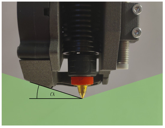
Figure 2.
Angle deduced from the printhead geometry as described by Ahlers [4].
This results in a non-evenly spaced mesh spanning the top of the part. An interpolant can be constructed to gain continuous high-density surface data. This is achieved by triangulating the input data and constructing piecewise cubic interpolating Bezier polynomials on each triangle, using a Clough–Tocher scheme described in [22]. The interpolation domain for this method is only the detected surface area. It is possible that sections of the part lie outside this domain (either due to numerical imprecisions or intentional design). Thus, a complementary interpolation method is needed to cover these regions. For this purpose, a simple nearest neighbor interpolation, as often used in image processing [23], is used. For both interpolation methods, the SciPy [24] Interpolation sub-package and the therein-contained method ‘griddata’ [25] can be used, specifying either ‘cubic’ or ‘nearest’ as the interpolation method.
To cover all regions as described and increase the mesh density, first, a fine, evenly spaced mesh in the x-y-plane is generated that covers the axis-aligned bounding box of the footprint of the whole 3D part. (The axis-aligned bounding box instead of the footprint itself is used due to the use of rectangular arrays. The implementation is significantly simplified by using the axis-aligned bounding box.) In the first step, the corresponding z-values for the newly generated mesh are interpolated using the described cubic interpolant. For all vertices outside the detected surface where no value is returned by the function, the interpolation is repeated using the described nearest neighbor interpolant. This ensures an interpolation domain that covers the whole part while not distorting vertices that lie outside the detected surface area.
2.2. Method 1: Adapting Layer Heights
The first method proposes an adaptive layer height throughout a layer, which leads to different extrusion rates while printing. This method can be divided into three main steps: first, the STL transformation by adapting the curved surface into a planar surface; second, the slicing of the part in a standard slicer; and third, the GCode scaling where the GCode is directly scaled in relation to the surface. This method extends Pelzer et al. [26]’s scaling planar GCode to the surface without defining a mathematical function. Figure 3 shows the steps used in method 1.
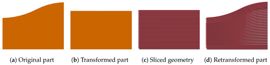
Figure 3.
Transformation using method 1 (cross-section view).
2.2.1. Adapting the Part Surface
To ensure that the slicer divides the part into full planes, it is essential to have a flat surface before performing the slicing operation shown in Figure 3b. The original STL model is modified by utilizing the interpolated and extrapolated surface as defined in Section 2.1.2. Special attention is given to the treatment of chamfered and rounded outer edges within the context of this algorithm. To have uniform upper and lower solid layers, this method divides the part into three sections (Figure 4b, ). The bottom section consists of planar layers, the middle section consists of non-planar layers with a variable layer height, and the top section consists of non-planar layers that are parallel to the surface and have a consistent layer height. is defined as the height of the bottom section, and is defined as the height of the top section.
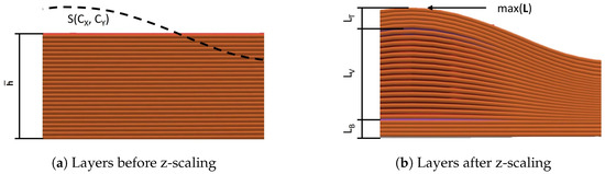
Figure 4.
Detailed illustration of the scaling process (cross-section view).
A single node from the STL model is defined by its coordinates, as shown in Equation (3). The mean height represents the arithmetic mean of all surface heights . The difference is defined as . Based on these values and the surface , can be calculated as follows (Figure 5a–c):
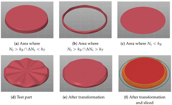
Figure 5.
The different areas (a–c) for = 40° of a part with a 45° chamfer, where (d) is the STL before, (e) after the transformation, and (f) after slicing.
Before rewriting these nodes into a new STL model, outliers are constrained to ensure that the values of remain within the range . Figure 5 shows the impact of the STL transformation on the test part within the individually defined regions.
2.2.2. Slicing with a Conventional Slicer
Once the component has been transformed into a part with a flat surface, it can be sliced into layers using a conventional slicer Figure 3c. To achieve this, selecting settings suitable for the respective printer is advisable. PrusaSlicer [15] was used for testing purposes and easy access through a command line interface (CLI). The paths generated in this way are then saved in the GCode file.
2.2.3. Scaling z-Axis and Material Extrusion
The generated GCode can now be scaled in relation to the surface. GCode consists of G and M commands, the most relevant of those being G1, which executes a linear movement of the extruder. The G1 command consists of the coordinates in the three-dimensional Euclidean space of the point to be reached and the machine parameters for the extrusion amount E and the feed rate F. Because most 3D printer firmware does not support non-linear moves in the z-direction, every move with length l is partitioned into several linear sections with a given maximal length . A more detailed description of this partitioning is described in Wüthrich et al. [17]. During testing, it was found that a partitioning length of less than 1 results in no measurable increase in part quality. This partitioning allows the printhead to approximate non-linear curves in the z-direction by short linear movements without any alterations to the printer firmware. The subdivided coordinates are then interpolated with the surface . The original planar GCode and the interpolated surface are shown in Figure 4a. Hereby, new parameters are introduced, which describe the scaling process more precisely. The current layer L is the index of the GCode layer starting from the bottom. The maximal layer is defined as the maximal height of the surface divided by the layer height . The number of constant layers is the sum of layers with a constant height at the top and the bottom . The variable layer number is defined as visualized in Figure 4b. Using these part-specific parameters and the given surface, the GCode can now be scaled to the new coordinates using the following non-continuous function:
The extrusion amount E is scaled based on the surface and depending on the gradient.
The process described in method 1 results in an overall part structure as seen in Figure 3d.
Certain geometries can make the layer height variance too big, making the parts no longer printable or only printable with difficulty. This will be described more in Section 2.4.
2.3. Method 2: Transforming Part
As in the first method, the second submitted method also transforms the object twice to achieve non-planar layers that follow the surface of the topmost layer of the object. This method divides the object into non-planar layers that are parallel to each other and are offset by a constant layer height . This results in an overall part structure, as seen in Figure 6d. At the bottom of the part, some planar layers can be introduced to increase bed adhesion and improve the surface quality of the part’s underside. Method 2 can be seen as an adapted approach to the method Zhao et al. [27] proposed for cylinder-based models. Zhao’s method transforms parts in relation to their surface geometry, which results in manufacturing limitations of the sides and undersides of parts but increases the surface geometries that can be printed in a non-planar way.
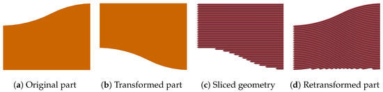
Figure 6.
Transformation using method 2 (cross-section view).
2.3.1. Transformation of the Part
In the first step before the slicing process, the original part, which consists of a triangular mesh provided by an STL file, is transformed so that the topmost surface of the part is planar (see Figure 6b). For each node of the mesh , the transformed node can be calculated by subtracting the z-value of the interpolation function defined in Section 2.1.2 and normalizing with the minimum overall z-value so that the lowest node has a :
To ensure this process does not cause any additional tessellation error, the mesh density needs to be high across the whole part (for more details, see [17]). Preferably, a constant mesh density is used throughout the entire part.
As in method 1 (Section 2.2.2), the new object is then passed into standard planar slicing software (see Figure 6c). The slicing software is configured not to generate any support material.
2.3.2. Retransformation of the GCode
The newly created GCode can then be transformed back to match the original part geometry. During this process, the previously planar layers are transformed into parallel, non-planar layers that match the surface detected in Section 2.1 (see Figure 6d). Because the movement of the printhead is given as a number of points in space, the retransformation of the GCode can be carried out by inverting the method applied in Section 2.3.1, which is given in Equation (9). Before the retransformation, the lines in the GCode must be split, as described for method 1 in Section 2.2.3.
Using this retransformation, a printable GCode can be obtained. Due to the layers meeting the print bed at an angle and no full layers making contact with the bed, the adhesion of the deposited thermoplastic to the bed is reduced and can lead to failed prints. To mitigate this issue, a small number of planar layers can be printed first. To still use standard slicing software without modification to the slicing algorithm, this introduces a second slicing process. The original untransformed object is split into a small base with height , which is sliced planar, and the rest of the object that is processed as described above.
2.4. Choosing Between Methods 1 and 2
It turns out that both methods are identical in terms of surface quality. The differences are in the optical quality of the side surfaces and in the printability.
Method 1 has the same number of layers over the entire part, resulting in a very regular layer structure on the outer edges of the parts and, therefore, also a good aesthetic appearance. With method 2, on the other hand, not all layers cover the entire component, which means that the layer ends are visible at the side edges (Figure 6d).
Large height variations can occur within a layer with method 1 for parts with a large width-to-height ratio and a significant overall height difference. With the Trilab Deltiq 2 printer used, reasonable layer heights are between 0.05 mm and 0.3 mm, which equals a ratio of 1:6 (Figure 7). Parts with a generally greater overall height and a width-to-height ratio of at least 1:6 are no longer printable with our approach because the angle of the steepest part is greater than the maximum printable angle (Section 2.1.2).
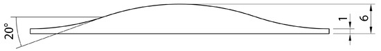
Figure 7.
Part geometry with a 1:6 ratio and a surface angle of 20°.
If parts with the geometric conditions described above are to be printed, attention must be paid to the size of the variation in the individual layers. If this is too large, method 2 must be selected so the parts can still be printed.
2.5. Ironing
One of the primary purposes of the methods discussed is the decreased surface roughness of printed parts. Various methods are used in planar FDM to decrease surface roughness. Chohan and Singh [28] provided a comprehensive overview of mechanical and chemical methods for the pre- and post-processing of FDM printed parts. All post-processing methods covered involve additional machinery or manual labor. Caputo et al. [29] have used ironing post-processing for planar FDM manufactured parts from PLA to eliminate any additional machinery or labor:
‘Ironing is the process of passing the topmost layer with the heated nozzle again while extruding (or not extruding) a low amount of material.’
Caputo et al. have shown that ironing post-processing can significantly increase the surface quality of printed planar parts in PLA. The same process can be implemented in CLFDM. The heated nozzle performs the slight remelting of thermoplastic. To increase surface quality, the nozzle passes the deposited filament tangentially to the top surface. Owing to the geometry of the nozzle tip with a flat surface with radius , part of the nozzle penetrates the surface of parts with sloping or curved top layers, as depicted in Figure 8b. This effect can be partially mitigated by offsetting the height of the nozzle by a small distance for ironing passes, depending on the gradient of the top surface and the nozzle geometry (see Equation (10) and Figure 8a,b).
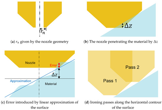
Figure 8.
Penetration compensation for ironing (cross-section view).
Experimental testing has shown Equation (11) to produce surfaces with fewer imperfections. This adaptation is based on a small number of printed samples and visual inspections of the parts. Thus, further experimentation would be required to ascertain the validity of this equation.
This offsetting in the z-direction has the effect seen in Figure 8c. After the ironing passes, some imperfections remain. This is due to Equation (10) approximating the non-planar surface through a tangential plane at the center of the nozzle. As can be seen in Figure 8c, this can lead to a variable error in if the surface of the actual part is not plane in the area of the nozzle. In practice, these errors are mainly due to the filament deposition of non-ironing passes not creating an ideal plane surface. If the average error along one ironing pass of the nozzle is larger than zero, some material accumulates in front of the nozzle. If the average error along one pass is less than zero, some unwanted indents of the part’s surface cannot be filled by the accumulated material and thus remain in the final part. Additionally, the nozzle geometry leads to the nozzle only touching the non-planar surface at a single point. Practically, this effect is negligible if the nozzle travels along the gradient line of the surface. If the nozzle travels in any other direction (in the most extreme case on the horizontal contour of the surface, as depicted in Figure 8d), not all parts of the surface are covered by the ironing passes. This leaves some surface imperfections that are not smoothed out.
3. Results and Discussion
3.1. Computing Time
Although the retransformation of the GCode with the division into the individual segments is particularly computationally intensive, it has been shown that the computation time is reasonable for components with a conventional construction size. To consider the computation times, two different components were calculated, each in four different scales (0.5, 1, 2, and 4). Table 1 shows the different computing times measured for the different parts.

Table 1.
Computation times for different parts.
The wavy disk (Figure 9a) with a diameter of 60 and an average height of approx. 5 and the simple wedge sample (Figure 9b) with a side length of 30 and an average height of approx. 7.5 . The times for the STL transformation, the slicing, the retransformation of the GCode, and the total computation time are listed. Method 1 was used for these measurements.
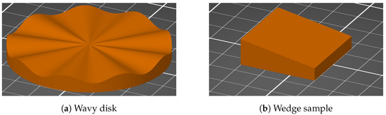
Figure 9.
Samples for measuring the computing time.
For parts exceeding a certain volume, the computation time is approximately proportional to the part’s volume and appears largely independent of its shape. The majority of the computation time is allocated to the retransformation of the GCode, while the transformation of the STL file requires minimal time, even for large parts. Slicing is also relatively fast compared to retransformation; as slicing is consistently performed in a planar manner, the time required for this step remains the same whether the printing process is planar or non-planar.
3.2. Printability
In addition to the limitations outlined in Section 2.1.1 (specifically, the maximum angle and the requirement for a continuous surface), the maximum variance in layer thickness serves as a criterion for determining whether a part is printable. To evaluate the boundaries of method 1, parts were printed with the highest possible variance in layer thickness. The part was sliced such that the middle layers encompassed the full range of layer thicknesses printable on the selected printer, from 0.05 to 0.3 . These tests demonstrated that the layers spanning this entire spectrum could be printed without issues (Figure 10).
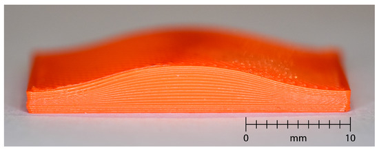
Figure 10.
Printed test part with variable layer height between 0.05 mm and 0.3 mm in section.
3.3. Surface Roughness
To obtain accurate measurements, the average surface roughness was measured on various planar and non-planar sliced and printed samples with a Keyence VR-6000 3D Optical Profilometer [30]. The measured samples are given in Table 2. As a sample geometry, a wedge with a ramp angle of 10°, as given in Figure 11, was used. Planar sliced samples were printed with layer heights ranging from 0.05 to 0.3 . Non-planar samples were sliced at a constant 0.2 as the layer height shows no influence on the surface quality of the top layer. To investigate the influence of the raster angle on the surface quality, the non-planar samples were each printed with 0° and 45° raster angles. Figure 12 shows GCodes views of different samples. Non-planar printed samples using ironing were included. All samples were printed using method 1, as the two methods had no measurable difference in surface quality. The roughnesses of Ra and Rz were both measured in four directions to be able to make a statement about the dependence on the printing direction (Figure 11).
Table 2.
Print settings for all samples.
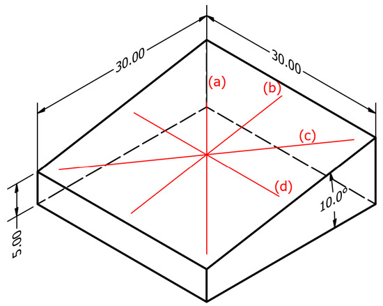
Figure 11.
Test part with a ramp angle of 10° and the measurement paths with (a): −45°, (b): 0°, (c): 45°, (d): 90°.
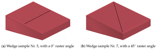
Figure 12.
GCode view of different wedge samples.
A reference part, in the form of a cube with dimensions of 30 × 30 × 5 , was also planar sliced and printed. Due to its cuboidal geometry, all layers—including the top surface—are aligned parallel to the print bed. This configuration facilitates the ironing of the top surface using standard slicer settings.
A Trilab Deltiq 2 printer with a linear-delta architecture was used for testing purposes. The linear delta architecture allows for uniform printing speeds in all three dimensions. To achieve a greater printable angle , a slightly modified printhead with a 0.4 E3D-Online belt nozzle from the Revo system was used. Further, the z-probe was mounted on a linear axis with a magnetic grid to move it to a higher z-level after homing to gain more clearance. The .stl models for the modification can be found in [31]. All samples were printed from Prusament PLA using 60 °C print-bed temperature and 220 °C nozzle temperature. The raster angle of the planar sliced and printed samples was not varied, as it did not influence the structure of the topmost layers of the samples.
The roughness measurements for the planar printed samples 3–6 are given in Table 3b. The values measured for Rz across layer changes (direction b: 0°) roughly correspond to the layer height . The values for Ra roughly correspond to when measured across layer changes (direction b: 0°). As seen in Table 3c, the surface quality of the non-planar parts 7 and 9 without ironing improves compared to the planar part 5 with the same layer height and thus also the same printing time. While the non-planar parts without ironing cannot improve on planar parts 3 and 4 with smaller layer heights, the deviation of the roughness Ra along a differently angled measurement axis can be reduced. This results in a more uniform surface, even though the maximum surface roughness is not reduced measurably. Additionally, the printing times can be improved massively compared to planar samples with comparable surface quality. Ironing leads to lower surface roughness than any of the planar samples. Again, the printing time is reduced massively compared to the planar sample 3 with the highest planar surface quality. It is observed that the surface finish of the non-planar printed samples 7–10 (wedge) appears comparable to that of the planar-printed reference samples 1 and 2 (cube). However, the average surface roughness of the ironed planar and non-planar samples in this study does not reach the low values reported by Caputo et al. [29] for planar ironed samples. This discrepancy may be attributed to the fact that Caputo et al. specifically optimized printing parameters to achieve minimal surface roughness, whereas the results presented here were obtained using the default settings in PrusaSlicer.
Table 3.
Surface quality comparison.
Both of the proposed methods yield the best overall results for Ra using raster angles of 0°. A comparison to sample 3 with a standard layer height of 0.2 is given in Figure 13. The stair-stepping effect of sample 3 is clearly visible. Sample 5 still shows some artifacts of the filament path that are mostly eliminated by ironing, as seen in sample 6. However, the part edges show larger imperfections in sample 6 than in sample 5. This effect can most likely be attributed to the nozzle remelting more material than necessary due to the offsetting error described in Section 2.5. The excess material is then left at the edges of the part as soon as the nozzle passes the edge and makes no contact with the part anymore.
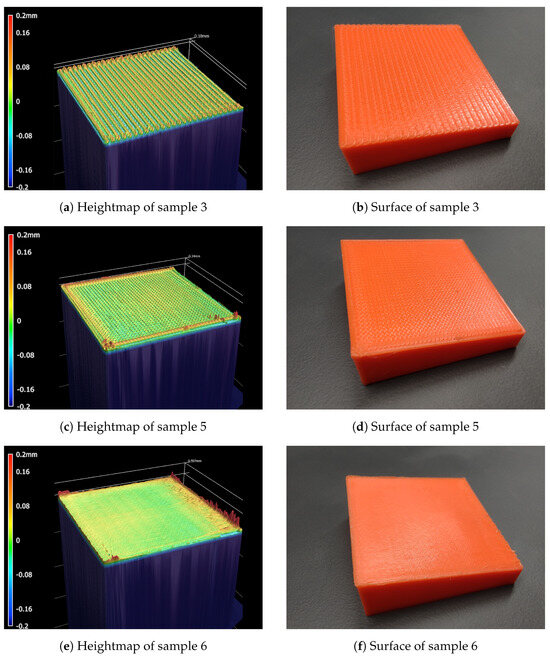
Figure 13.
Surface quality comparison for samples 3, 5, and 6.
Various printing tests were carried out with different geometries. One test part is a round disk with a wavy surface. Its planar printed surface is shown in Figure 1b. This part was also non-planar printed and is shown in Figure 14a without ironing and in Figure 14b with ironing.
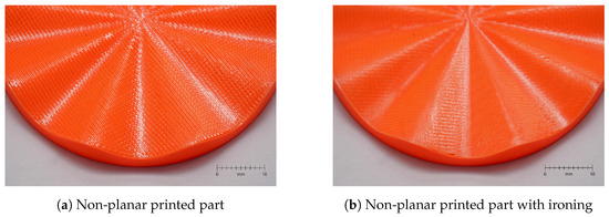
Figure 14.
Non-planar printed test parts with a wavy surface.
The results show that the proposed non-planar printing strategies improve surface uniformity and reduce roughness compared to planar printing at equivalent layer heights. While ironing achieves the lowest roughness, the values remain higher than those reported in other publications, likely due to unoptimized parameters. Non-planar methods also reduce roughness variation across measurement axes, enhancing surface consistency. These findings demonstrate the potential of non-planar printing for complex geometries and high-quality surfaces, though further optimization is needed.
3.4. Limitations
Certain limitations to the proposed methods must be acknowledged (as also mentioned in Section 2.1.1). The fixed orientation of the printhead in most three-DOF gantry and delta architecture printers imposes constraints, particularly due to the risk of collisions between the printhead and pre-printed structures. This issue highlights the need for collision detection, which could be addressed by incorporating a parameterized printhead model into the slicing process. Such a model would account for variables such as the maximum printing angle and the height achievable without collision.
Additionally, the approach is currently limited to continuous surfaces without steps, as the detection of discontinuities or surface transitions is not yet implemented. Finally, while tests confirmed that layers with significant thickness variance (0.05 to 0.3 ) could be printed without issue, the method’s applicability to more complex geometries or extreme surface transitions remains to be evaluated. Future refinements to the algorithm will be necessary to address these limitations and expand the method’s versatility.
4. Conclusions
To conclude, the challenge of reducing the stair-stepping effect, mostly seen in FDM 3D-printed parts with low ramp angles, was addressed. To achieve this, algorithms were developed to modify the slicing process for non-planar layer deposition. Two methods were introduced to reduce surface roughness. Firstly, the layer heights within each layer are adjusted, and second, the entire object is transformed to achieve non-planar layers. The test results on a sample part with a ramp angle of 10 degrees proved the effectiveness of the proposed methods in reducing surface roughness or printing time, respectively. The surface quality of the non-planar prints was further improved by implementing ironing post-processing.
Surface roughness investigations reveal improved average surface roughness compared to planar printed parts. Notably, the surface roughness Ra could be reduced from 37.7 μm to 13.7 μm for parts with the same standard layer height of 0.2 mm and the same printing times. The ironing post-processing further decreased the surface roughness to 6.9 μm, trading surface quality for additional printing time. However, this ironing process also has certain challenges that need to be considered in more detail. For example, the nozzle penetrates the material due to the shape of non-planar paths, which has a negative impact on the surface quality. This problem has already been mentioned in [4]. Optimized nozzle shapes (e.g., rounded edges) or multi-axis printers, which always keep the nozzle at right angles to the surface, could provide a solution. Ironing also shows that a certain amount of material build-up can occur. This happens when the nozzle is too low, and it not only smooths the material on the surface but also takes material with it, which then builds up on the edge of the part. This is an issue that should be reduced with a more optimal height positioning of the nozzle. In addition, the approaches already mentioned (nozzle shape and multi-axis printers) could also be considered to address this problem.
The results reported provide insights into adapting commercial slicing software for non-planar FDM printing. The proposed methods could deliver improvements to engineering, aviation, and biomedical applications, where surface quality is of greater importance. Most importantly, these adaptations can be implemented with no greater expense in time or material.
Another step to make the proposed ideas widely applicable is to provide a solution for surfaces with discontinuities. If this is solved, these methods can easily slice and print non-planar surfaces with good quality. It is also possible that non-planar printed layers have better properties in terms of anisotropy, but at the moment, no statement can be made about a relevant increase in structural stability. A potential disadvantage of non-planar printing with variable layer heights is the increased likelihood of larger or more frequent voids within the printed part, which may negatively affect its structural properties, as noted by Gonabadi et al. in [32]. Further investigation would be necessary to explore this effect in greater detail.
As mentioned in Section 2.2.3, all lines are divided into short segments. To reduce the size of the GCode, this could be further optimized, and, for example, straight lines could not be further subdivided.
Author Contributions
Conceptualization, M.W.; methodology, M.W.; software, S.M. and S.Z.; validation, S.M. and S.Z.; formal analysis, S.M., S.Z. and M.W.; investigation, S.M., S.Z. and M.W.; resources, S.M., S.Z. and M.W.; data curation, M.W.; writing—original draft preparation, S.M. and S.Z.; writing—review and editing, M.W.; visualization, S.M. and S.Z.; supervision, M.W.; project administration, M.W. All authors have read and agreed to the published version of the manuscript.
Funding
This research received no external funding.
Data Availability Statement
Data are contained within the article.
Conflicts of Interest
The authors declare no conflicts of interest.
Abbreviations
The following abbreviations are used in this manuscript:
| CLFDM | Curved-Layer Fused Deposition Modeling |
| FDM | Fused Deposition Modeling |
| STL | Stereolithography file format |
| CAD | Computer-Aided Design |
| DOF | Degree Of Freedom |
| CLI | Command Line Interface |
| PLA | Polylactic acid |
References
- Kumar, S.A.; Prasad, R. Chapter 2—Basic principles of additive manufacturing: Different additive manufacturing technologies. In Additive Manufacturing; Woodhead Publishing Reviews: Mechanical Engineering Series; Woodhead Publishing: Sawston, UK, 2021; pp. 17–35. [Google Scholar]
- Wong, K.V.; Hernandez, A. A Review of Additive Manufacturing. ISRN Mech. Eng. 2012, 2012, 1–10. [Google Scholar] [CrossRef]
- Hu, J. Study on STL-Based Slicing Process for 3D Printing. In Proceedings of the 2017 International Solid Freeform Fabrication Symposium, Austin, TX, USA, 7–9 August 2017. [Google Scholar]
- Ahlers, D.; Wasserfall, F.; Hendrich, N.; Zhang, J. 3D Printing of Nonplanar Layers for Smooth Surface Generation. In Proceedings of the 2019 IEEE 15th International Conference on Automation Science and Engineering (CASE), Vancouver, BC, Canada, 22–26 August 2019. [Google Scholar]
- Kiński, W.; Pietkiewicz, P. Influence of the Print Layer Height in FDM Technology on the Rolling Force Value and the Print Time. Agric. Eng. 2019, 23, 1–9. [Google Scholar] [CrossRef]
- Al-Maharma, A.Y.; Patil, S.P.; Markert, B. Effects of porosity on the mechanical properties of additively manufactured components: A critical review. Mater. Res. Express 2020, 7, 122001. [Google Scholar] [CrossRef]
- Wickramasinghe, S.; Do, T.; Tran, P. FDM-Based 3D Printing of Polymer and Associated Composite: A Review on Mechanical Properties, Defects and Treatments. Polymers 2020, 12, 1529. [Google Scholar] [CrossRef] [PubMed]
- Gonabadi, H.; Hosseini, S.F.; Chen, Y.; Bull, S. Structural analysis of small-scale 3D printed composite tidal turbine blades. Ocean Eng. 2024, 306, 118057. [Google Scholar] [CrossRef]
- Wang, W.; Chao, H.; Tong, J.; Yang, Z.; Tong, X.; Li, H.; Liu, X.; Liu, L. Saliency-Preserving Slicing Optimization for Effective 3D Printing. Comput. Graph. Forum 2015, 34, 148–160. [Google Scholar] [CrossRef]
- Delfs, P.; Toews, M.; Schmid, H.J. Surface roughness optimized alignment of parts for additive manufacturing processes. In Proceedings of the 26th Annual International Solid Freeform Fabrication Symposium, Austin, TX, USA, 10–12 August 2015; Volume 26, pp. 1334–1344. [Google Scholar]
- Chakraborty, D.; Aneesh Reddy, B.; Roy Choudhury, A. Extruder path generation for Curved-Layer Fused Deposition Modeling. Comput.-Aided Des. 2008, 40, 235–243. [Google Scholar] [CrossRef]
- Shan, Y.; Gan, D.; Mao, H. Curved Layer Slicing based on Isothermal Surface. Procedia Manuf. 2021, 53, 484–491. [Google Scholar] [CrossRef]
- Feng, X.; Cui, B.; Liu, Y.; Li, L.; Shi, X.; Zhang, X. Curved-layered material extrusion modeling for thin-walled parts by a 5-axis machine. Rapid Prototyp. J. 2021, 27, 1378–1387. [Google Scholar] [CrossRef]
- Nayyeri, P.; Zareinia, K.; Bougherara, H. Planar and nonplanar slicing algorithms for fused deposition modeling technology: A critical review. Int. J. Adv. Manuf. Technol. 2022, 119, 2785–2810. [Google Scholar] [CrossRef]
- Prusa Research. PrusaSlicer. Available online: https://www.prusa3d.com/en/prusaslicer/ (accessed on 27 November 2024).
- Ultimaker. Cura. Available online: https://ultimaker.com/software/ultimaker-cura/ (accessed on 27 November 2024).
- Wüthrich, M.; Gubser, M.; Elspass, W.J.; Jaeger, C. A Novel Slicing Strategy to Print Overhangs without Support Material. Appl. Sci. 2021, 11, 8760. [Google Scholar] [CrossRef]
- Maissen, S.; Zürcher, S. GitHub Repository. Available online: https://github.com/RotBotSlicer/Nonplanar_Slicing/ (accessed on 27 November 2024).
- Jin, Y.; Du, J.; He, Y.; Fu, G. Modeling and process planning for Curved-Layer Fused Deposition. Int. J. Adv. Manuf. Technol. 2016, 91, 273–285. [Google Scholar] [CrossRef]
- Huang, B.; Singamneni, S. Curved-Layer Adaptive Slicing (CLAS) for fused deposition modelling. Rapid Prototyp. J. 2015, 21, 354–367. [Google Scholar] [CrossRef]
- Singamneni, S.; Roychoudhury, A.; Diegel, O.; Huang, B. Modeling and evaluation of Curved-Layer Fused Deposition. J. Mater. Process. Technol. 2012, 212, 27–35. [Google Scholar] [CrossRef]
- Alfeld, P. A trivariate clough—Tocher scheme for tetrahedral data. Comput. Aided Geom. Des. 1984, 1, 169–181. [Google Scholar] [CrossRef]
- Parker, J.A.; Kenyon, R.V.; Troxel, D.E. Comparison of Interpolating Methods for Image Resampling. IEEE Trans. Med Imaging 1983, 2, 31–39. [Google Scholar] [CrossRef]
- Virtanen, P.; Gommers, R.; Oliphant, T.E.; Haberland, M.; Reddy, T.; Cournapeau, D.; Burovski, E.; Peterson, P.; Weckesser, W.; Bright, J.; et al. SciPy 1.0: Fundamental Algorithms for Scientific Computing in Python. Nat. Methods 2020, 17, 261–272. [Google Scholar] [CrossRef]
- SciPy Griddata. Available online: https://docs.scipy.org/doc/scipy/reference/generated/scipy.interpolate.griddata.html (accessed on 27 November 2024).
- Pelzer, L.; Hopmann, C. Additive manufacturing of non-planar layers with variable layer height. Addit. Manuf. 2021, 37, 101697. [Google Scholar] [CrossRef]
- Zhao, G.; Ma, G.; Feng, J.; Xiao, W. Nonplanar slicing and path generation methods for robotic additive manufacturing. Int. J. Adv. Manuf. Technol. 2018, 96, 3149–3159. [Google Scholar] [CrossRef]
- Chohan, J.; Singh, R. Pre and post processing techniques to improve surface characteristics of FDM parts: A state of art review and future applications. Rapid Prototyp. J. 2017, 23, 495–513. [Google Scholar] [CrossRef]
- Caputo, M.; Rashwan, O.; Waryoba, D.; McDade, K. Surface texture and thermo-mechanical properties of material extruded and ironed polylactic acid. Addit. Manuf. 2022, 59, 103084. [Google Scholar] [CrossRef]
- Keyence. Keyence VR-6000. Available online: https://www.keyence.com/products/microscope/macroscope/vr-6000/ (accessed on 27 November 2024).
- Wüthrich, M. Trilab Mod. Available online: https://www.printables.com/model/798333-trilab-deltiq2-printhead-modification-to-gain-clea (accessed on 27 November 2024).
- Gonabadi, H.; Hosseini, S.F.; Chen, Y.; Bull, S. Size effects of voids on the mechanical properties of 3D printed parts. Int. J. Adv. Manuf. Technol. 2024, 132, 5439–5456. [Google Scholar] [CrossRef]
Disclaimer/Publisher’s Note: The statements, opinions and data contained in all publications are solely those of the individual author(s) and contributor(s) and not of MDPI and/or the editor(s). MDPI and/or the editor(s) disclaim responsibility for any injury to people or property resulting from any ideas, methods, instructions or products referred to in the content. |
© 2024 by the authors. Licensee MDPI, Basel, Switzerland. This article is an open access article distributed under the terms and conditions of the Creative Commons Attribution (CC BY) license (https://creativecommons.org/licenses/by/4.0/).