Abstract
This article develops and demonstrates a set of design-focused manufacturability constraints for the fused deposition modeling/fused filament fabrication (FDM/FFF) process. These can be mapped from the basic behavior and process characteristics and formulated in terms of implicit or explicit design constraints. When the FDM/FFF process is explored and examined for its natural limitations and behavior, it can provide a set of manufacturing considerations (advantages, limitations, and best practices). These can be converted into manufacturing constraints, which are practical limits on the ability of the process. Finally, these can be formulated in terms of design–useful manufacturability constraints. Many of the constants and parameters must be determined experimentally for specific materials. The final list of 54 major manufacturability constraints presented in this work will better inform designers considering using FDM/FFF as a manufacturing process, and help guide design decisions. After derivation and presentation of the constraint set, extensive discussion about practical implementation is provided at the end of the paper, including advice about experimentally determining constants and appropriate printing parameters. Finally, three case studies are presented which implement the constraints for simple design problems.
1. Introduction
One of the most well-developed and mature additive manufacturing (AM) processes designed for polymer and polymer-composite materials is the fused deposition modeling (FDM) process; this process is also sometimes called fused filament fabrication (FFF), or simply material extrusion AM [1,2,3]. The process typically works by extruding a molten bead (sometimes also called a “road”) of thermoplastic material into elements to selectively trace out the layers of the part. The fusion between the previous layer and the neighboring elements is accomplished via a polymer melt reaction [4,5,6,7,8]. The extruder position and path are driven using g-code (similar to a CNC milling machine); the process is typically monitored by an open-loop control system based on stepper motor position encoders, but other control systems exist [6,7,9,10,11]. The essential hardware components of an FDM machine are the extruder (for melting and depositing the molten raw material), the frame, and the build plate (Figure 1). A number of configurations are available (some examples are shown in Figure 2a–d), each with its own set of advantages and disadvantages; there are others (such as delta robots and robotic arm printers), but the ones shown are the most common 3-degrees-of-freedom configurations. For the purposes of this article, it is assumed that the design process for printed parts is the same regardless of the hardware configuration.
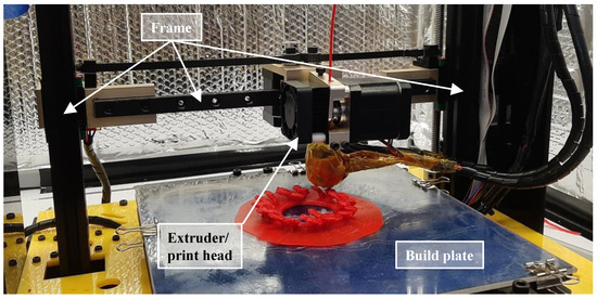
Figure 1.
Typical hardware for the FDM process.
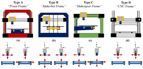
Figure 2.
Most common 3-degree-of-freedom (DoF) hardware configurations ((a) Prusa-type frame, (b) Makerbot-type frame, (c) Makergear-type frame, and (d) CNC-type frame), with the degrees of freedom for the extruder and build plate shown in each case. Others exist, such as those built around delta robots and higher-DoF robotic arms.
FDM is a scanning-type AM (ST-AM) process, building each layer as a series of elements laid out in a pattern, typically bounded by a solid shell of elements printed on the outside boundary of each layer. Examples of other ST-AM processes include most laser powder bed fusion processes and laser-based stereolithography. ST-AM is the most common type of AM process, but others exist based on full-layer projection (such as digital light processing) and inkjet-like printing (such as Polyjet and binder jetting processes).
For ST-AM processes, especially FDM, the final bulk material contains small voids/inclusions and is highly anisotropic [12]; however, the pattern of the laid out elements is designable, allowing FDM to be used to create structured and tailored materials by controlling or optimizing the layout of the elements [13,14,15,16]. Effective design of the FDM structure requires knowledge and control of a variety of parameters, the most commonly studied of which are the nominal density, element layout (typically raster angle), layer thickness, print orientation, deposition speed, and processing temperature. A sampling of 30 recent papers related to FDM and discussing manufacturing parameters was collected to determine which parameters are considered most often; the results are shown in Table 1. Material choice was not considered as a parameter in this table, as the best ranges and limits on parameters are dependent on material choice. In most FDM studies, the materials under considerations are treated as separate problems, since each material will have different optimal parameters and constraints. Some FDM materials are amorphous (such as acrylonitrile butadiene styrene (ABS) and polycarbonate) and some are semi-cystalline (such as polylactic acid (PLA) and polyamides (nylon)).

Table 1.
Example parameter control/optimization studies from a review of 30 recent papers on FDM.
This concept paper explores the manufacturability constraints (and some related mechanics) for the FDM process. First, the basic, high-level, set of manufacturability constraints specifically for the FDM process is derived. Section 3 refines the constraint set relative to some common materials (ABS, PLA, and polycarbonate) selected for demonstration purposes; this included experimental determination of some of the constraints and sensitivity analysis of the stated assumptions. Finally, three case studies are presented in Section 4 to better demonstrate the concepts presented in this work.
2. FDM Manufacturability Constraints: Concepts
2.1. Parameters vs. Constraints
The printing parameters, being the main drivers for the final material properties for FDM-processed materials, can provide design variables and aid in the development of objective functions [17,22,24] during design. However, the constraints on and between these parameters is an important area which has received little to no attention in the AM literature thus far. Simple example constraints for the parameters shown in Table 1 are given in Table 2. Others certainly exist (including some complex equality constraints that describe relationships between the parameters); however, these provide excellent conceptual examples to demonstrate some kind of relationship between manufacturing parameters and manufacturability constraints. The realistic constraints that will be explored by this concept paper will be far more detailed and specific than the examples shown in Table 2.
Table 2.
Example constraints for the general parameters found during the survey presented in Table 1.
The proper formulation of any design problem requires at least one design objective and a design space to explore for answers which satisfy the objective [44]. In most problem formulations, this involves the identification of decision or design variables, formulation of an objective function, and definition of the design space via a set of constraints. Some toy problems and cases with obvious optima or single global solutions do not need constraints [45,46], but most practical problems will. While the objective function will always be a function of the decision variables, the constraints may take two forms: (1) a function of decision variables or (2) simple bounds on the possible values of each decision variable. For manufacturing-related problems, the bounds will be more commonly encountered [16,47,48,49]. As previously discussed, the various manufacturing parameters provide excellent objective functions and design variables, but do not provide rigorous constraints. In order to avoid manufacturability problems with the final designs [48,50,51] and avoid simplifying the design too much (as is often done in traditional design-for-manufacturing techniques [52,53,54]), it is vital that accurate and useful constraints are generated.
2.2. Mapping Manufacturing Knowledge to Design Constraints
The advantages, limitations, and best practices related to specific manufacturing processes are vital considerations during product design. This is especially true when using complex design methods (e.g., those generated using algorithms, such as topology optimization), as the final design may not actually be manufacturable without the imposition of the manufacturability constraints. This requires a rigorous process of mapping the useful manufacturing knowledge into design-focused manufacturability constraints; the purpose of these is to limit the design candidates to those which are manufacturable using a particular process or series of processes [55,56,57,58,59,60]. Different design scales must also be considered during this mapping; the basic scales referred to in this paper are defined in Figure 3.
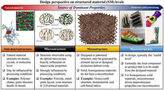
Figure 3.
Design scales for materials and parts/products referred to throughout this paper. The mesostructure level will be the most often used and discussed. This chart shows examples of non-polymer materials for completeness, but it should be noted that nearly all FDM materials are thermoplastic polymers.
Manufacturing processes can be classified according to type (subtractive, additive, formative), family (e.g., machining processes), and individual process mechanics [61]. At each of these classifications, a list of process characteristics can be made; the items on this list may overlap heavily with other processes of the same type or family or may be unique to a single process. These characteristics can be divided into advantages, disadvantages, and best practices. The advantages provide some kind of clear cost or schedule benefit or open up the list of possible designs and design features the process can fabricate. The disadvantages do the opposite, helping decrease the size of the design space or increasing cost and schedule issues. Best practices are effectively “soft constraints” which could be either an advantage or disadvantage in particular cases and must be evaluated. The list of manufacturing considerations can cover a very large domain, as shown in Figure 4.
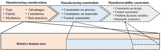
Figure 4.
Basic mapping and domain sizes for general manufacturing processes.
Once the set of manufacturing considerations is established (at least conceptually), a set of manufacturing constraints arise naturally. For example, a manufacturing consideration for a machining process is that the cutting tool will generate both force and heat during operation. This naturally implies two manufacturing constraints: (1) that a machined feature must be thick enough to withstand the cutting force from the tool and (2) a feature must be large enough to dissipate heat without damaging the feature or material microstructure. The manufacturing constraints should be more formal than the manufacturing considerations and may require some expert intuition and experience to fully translate in some cases. The manufacturing constraints are also related to the material choice, but whether they are depending on the material selection or vice-versa will be depend on the problem at hand. Since these constraints are based on a specific process and specific set of conditions, the domain is contained within but significantly smaller than that of the manufacturing considerations (Figure 4).
The term “manufacturing” can have a variety of meanings, but one that is widely used and relevant to this work is the definition given by DeGarmo’s Materials and Processes in Manufacturing. Paraphrased, manufacturing is the performance of a series of operations on a product, raw material, or other item such that the successful completion of each operation or step increases its utility or monetary value [61]. With this in mind, the steps to manufacture a product will require a subset of the possible steps that a particular process or set of processes are capable of taking. Therefore, the domain (Figure 4) for the manufacturability constraints (imposed on the design, not the manufacturing process) will be the smallest of the three; this makes sense when considering that the set of relevant constraints bounds the design space for a specific design or design family. In summary:
- The manufacturing considerations are observed or collected by designers and/or experts in manufacturing science. These may be quite conceptual and may be at the level of process type (subtractive (SM), additive (AM), formative (FM)), process family, or specific process and material combination. Manufacturing considerations may provide advantages (e.g., AM increases possible design complexity over machining), limitations (e.g., in machining, features must be reachable by cutting tools), or guidelines/soft constraints (e.g., it is better to machine metal and mold engineering plastics when possible);
- The manufacturing considerations can (typically) be easily converted into manufacturing constraints (i.e., bounds on the applicability of the process);
- The manufacturability constraints on the design itself result directly from the limitations of the manufacturing process and material used.
2.3. FDM: Manufacturing Considerations
The four basic levels of analysis (system, extruder, element design, and element extrusion/fusion) for the FDM process are shown in Figure 5, from which the basic manufacturing considerations can be collected. Assuming a standard FDM machine design with three degrees of freedom, eight essential manufacturing considerations apply (Figure 6):
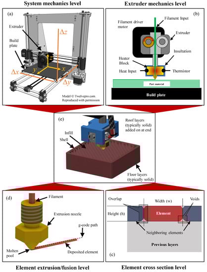
Figure 5.
Levels of analysis for FDM. (a) System level, (b) extruder level, (c) element geometry level, and (d) element deposition/fusion level. Panel (e) shows the full process.
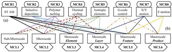
Figure 6.
Mapping from the (a) basic eight manufacturing considerations to the (b) six sets of manufacturing constraints at each level of analysis for FDM.
- MCR1—ST-AM: FDM is a scanning-type AM process, where each layer is built from a series of elements (typically of uniform cross-section) which do not fully merge into each other and form an anisotropic material with natural voids and inclusions which may be designed or optimized (Figure 5a,d,e) [8,12,13,14,16,20,49,62,63];
- MCR2—Selective Deposition: Deposition of the raw material is accomplished by extruding a filament through a heated die and selectively depositing it to form the essential elements (Figure 5b–e) [12,20,49,63,64,65];
- MCR3—Polymer Melting: The fusion is accomplished via polymer melting (Figure 5b–d) [63,66,67,68,69,70,71,72];
- MCR4—Thermal Cycling: The bulk material is subjected to uneven thermal cycling during operations (Figure 5b) [66,67,68,70,73,74];
- MCR5—Isotropic Elements: Each element is approximately isotropic or transversely isotropic in terms of mechanical properties (Figure 5b–d) [12,63,75,76,77,78,79,80];
- MCR6—G-Code Control: The extruder die is controlled (generally using an open-loop controller or step counting in the motors) using g-code (Figure 5a,d) [12,49,63,67,81,82,83,84];
- MCR7—X/Y Motion: Motion of the extruder in X or Y directions builds each layer (Figure 5a) (definition for standard 3 DoF system);
- MCR8—Z Motion: Motion of the extruder in Z adds more layers (Figure 5a) (definition for standard three DoF system).
It should be noted here that this model and understanding of FDM is somewhat idealized in order to better understand the process from the perspective of a designer. While the mechanics are the same, the are some considerations that must be taken into account for very detailed and specific studies, say, for example, modeling the melt pool itself as a function of polymer rheology properties. As the material is interacting with the nozzle, there will be small wall slip effects and pressure drop effects, among other things. From the perspective of the product designer, these may or may not be important. This determination will need to be made by each designer, as it is impossible to create a perfect model and the more complex the model is, the more expensive it is.
2.4. FDM: Manufacturing Constraints
Given the manufacturing considerations from the previous section, the manufacturing constraints may be derived. In order to do this in a consistent and useful way, it is important to recognize that the bulk parts or products fabricated via FDM are structured materials, whether or not they are designed [12,13,14,20,62,63]. As such, it is necessary to examine FDM at several scales, which correspond to specific levels of analysis, shown in Figure 3. As demonstrated in Figure 6, FDM can be analyzed at the macro-level (e.g., a small part or large feature), the meso-level (e.g., the “structured” level of the part or product), the micro-level, and the sub-micro-level. It is assumed in this section that the reader has a basic understanding of polymer material behavior and the mechanics of the FDM process. In case of doubt, refer to an earlier section of the paper or one of the references.
2.4.1. Sub-Microstructure Level
At the sub-micro level, the basic material properties of the polymers in use determine the manufacturing constraints (Figure 7). The homogeneity of the local material units (driven often by the quality of the filament used) and the rheology of the polymer determine the manufacturing constraints at this level. These things, in general, must be determined experimentally for each polymer or polymer composite used, and limited choices are currently available since most FDM materials are thermoplastics. It is difficult to impossible to design the specific properties at this level, so the designer is typically required to consider these as fixed parameters (if a material is specified) or criteria for material selection (if not pre-selected). The rheological parameters (including the polymerization behavior and state) are mainly determined by the operating temperature and associated rheological properties for thermoplastics at this level [4,85], so temperature must be carefully specified or established when taking property data or observing behavior. At the sub-micro level, the processing conditions have little to no direct influence, so the experiments used do not have to be directly related to FDM to draw useful conclusions. As shown in Figure 7, seven basic manufacturing constraints directly from FDM can be mapped from the manufacturing considerations at this level.
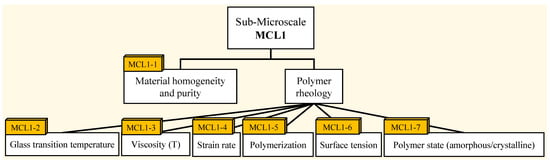
Figure 7.
Essential manufacturing constraints at the sub-microscale level.
2.4.2. Microstructure Level
For the micro level (Figure 8), the material properties and processing conditions both influence the manufacturing constraints. Things such as the quality of the polymer chain reformulation (i.e., bonding) after extrusion and fusion, the amount of residual stress in and between each element, the state of the polymer chain (amorphous or semi-crystalline), and the amount of shrinkage (which may be related to residual stresses) after cooling drive the manufacturing constraints at this level. As with the sub-micro level, the values of the resulting manufacturing constraints must be determined experimentally.
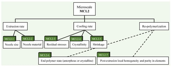
Figure 8.
Essential manufacturing constraints at the microscale level.
2.4.3. Mesostructure Level
Using the definition for “meso level” given in Figure 3, FDM will have two levels of mesostructure, one at the individual element level (Figure 9) and one at the layer level (Figure 10). This is due to its nature as a scanning-type AM (ST-AM) process (Figure 5) and the fact that both the element geometry and the layout of the elements (i.e., the layer) can be designed in a simple mechanical way. These two sub-levels will have the largest set of manufacturing constraints of all the levels, but most of these will be simple bounds and inequality constraints. For these levels, the processing conditions and layout of the elements has a much larger impact on the final bulk properties of the part or product than the basic material properties. Of course, the constraints from the sub-micro and micro levels also impact the problem at the meso level through the properties of each element:
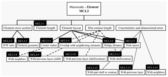
Figure 9.
Essential manufacturing constraints at the single-element mesoscale level.
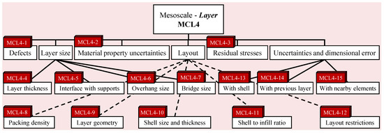
Figure 10.
Essential manufacturing constraints at the single-layer mesoscale level.
- Single element mesostructure: As seen in Figure 5c, the element cross section and length can be designed in a similar way to a simple beam or truss member. The major manufacturing constraints at this level (Figure 9) are the selected geometry, height-to-width ratio, minimum length, minimum corner radius, minimum connection length with the last layer and neighboring elements, and a number of other constraints including the various dimensional errors. Given that FDM elements are produced via extrusion, selectively laid out, and are approximately isotropic or transversely isotropic, they can often be seen and treated similarly to beams in design problems;
- Single layer mesostructure: Similar to the single element mesostructure, the single layer element layout can be designed to have controllable (to some degree) mechanical properties. The most important of the manufacturing constraints for this level are restrictions on layer geometry, print direction, position accuracy uncertainties, element packing density, minimum useful layer thickness, the number of shells (“contours” in some of the literature), and the ratio of the shell area to the infill area for the layer. There are a number of others, as shown in Figure 10, which may be relevant. Following on from the discussion concerning the treatment of elements as beams in design problems, the layers may often be designed similarly to 2-D or 2.5D truss problems in practice.
2.4.4. Macrostructure Level
At the macro (“useful”) level, it is assumed that many layers of printed material are present. The size of macroscale features can range from an individual feature to the whole final part or product. In the case of FDM, this level can be further divided into two regions:
- Feature-level macrostructure: Manufacturing constraints at this level (Figure 11) include things like the printing orientation, the minimum layers to be printed, the roof and flood thickness, and interfaces with support material and other features on the part or product. Most of the existing feature catalogs and feature-level design for additive manufacturing guidelines focus on this level; examples include [86,87,88,89,90,91];
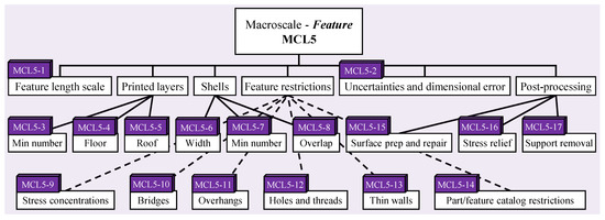 Figure 11. Essential manufacturing constraints at the macroscale (feature) level.
 - Part/product-level macrostructure: This level (Figure 12) is the one that will be directly observed or tested by most users and product/part designers and so the manufacturing constraints are mainly concerned with final appearance, post-processing, dimensional accuracy, and interfaces/tolerances with other parts. General product design and success criteria mainly apply to this level. If the additively manufactured product is to be post-processed, it will typically be done with the product-level macroscale in mind.
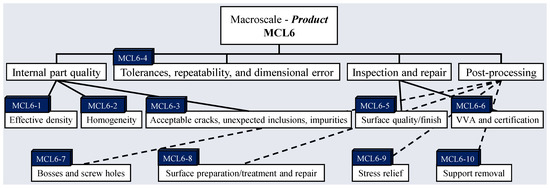 Figure 12. Essential manufacturing constraints at the macroscale (product) level.
2.5. FDM: Manufacturability Constraints
Given the large set of derived manufacturing constraints (i.e., limits on the process capabilities) explored in the previous section, a set of manufacturabilty constraints (i.e., on the design of a product to be fabricated using FDM) can be found. The step of mapping from the process limits to the design limits is a much more simple task than defining or finding all of the relevant process limits. Essentially, for each limit or set of limits, an equivalent design limit must exist to accommodate the parent process limit(s). These design limits (manufacturability constraints) can be used directly in design problems to guarantee (or at least better ensure) that that the final product is indeed manufacturable using FDM.
Compiling all of the process constraints discussed in Section 2.4 (and combining/ refining as needed), the set of design constraints at each level can be found, as shown in Table 3. Finding these constraints is fairly straightforward given the information from Section 2.4 and no special processes are required. In most cases, each of the manufacturability constraints will have more than one parent manufacturing constraint; likewise, a manufacturing constraint may drive more than one manufacturablity constraint. For thermoplastic FDM, all of the constraints directly drive the design decisions; however, in practice, some of the constraints simply drive the selection of materials, some of them limit the printing parameters, and some directly impact the design. Notes are given in the table for each case. Note that exact constraints cannot be derived without selecting a material and possibly collecting some experimental data, due to the different behavior of each of the FDM polymers. In addition, the constraints may not be independent of each other.
Table 3.
Manufacturability constraints mapped from the manufacturing constraints and manufacturing consideration for the FDM process. These constraints are subject to three major assumptions: (1) The system has three degrees of freedom, (2) the extruder has a fixed round extrusion nozzle, and (3) the printer hardware is properly tuned. Definitions for the terms in the type, form, parent(s), and method columns are provided, mainly in Section 2.5.
The mapped conceptual manufacturability constraints for FDM are shown in Table 3. A total of 54 were identified, but not all of them will apply to all design problems. The large majority of these fall into two categories when not used as constraints:
- Build parameters: Designated as “PP-CN” type constraints in Table 3, these may be used as print parameters or constraints, depending on the objectives and needs of the design. In practice, a mix of constraints and parameters will likely be used;
- Confounding factors: Confounding factors are those which have some influence on a model or system, but the influence is not necessarily known or understood when these are not directly controlled. Designated as “CF-CN” type constraints in Table 3, these could be considered as largely “noise” variables in FDM processes, but could also be controlled or used as constraints in design problems.
The remaining constraints (“CN” in Table 3) are simple constraints (generally generated by the stakeholders as part of the project requirements). The type and form of the constraints should be considered separately in order to best formulate them and use them effectively in the design problem at hand. Just as the type of constraint may be simple (CN), parameter (PP-CN), or confounding factor (CF-CN), the form of the constraints may also be divided into three major categories (Table 3), depending on its main source:
- Build parameters (BP): Constraints directly on the build parameters. These will almost always be simple bounds (e.g., minimum and maximum raster angle) on the parameter in question;
- Material selection (MS): Constraints either driven by or driving material selection (depending on the progress of the design process). These may take the form of bounds, inequality constraints, and equality constraints, depending on what is considered. In the experience of the authors, the more complex constraint equations (e.g., the equality constraints) can be simplified dramatically by setting some variable values to fixed parameters;
- Geometric constraints (GS): These constraints may be driven by design rules (e.g., [87,88]) or by looking at geometric relationships in the design. While any non-bound functions are likely to be simple continuous functions, the possibility of having both inequality and equality constraints often necessesitates simplification, similar to what is done for material selection.
The realistic determination of the constraints may be done in eight major ways in practice (Table 3), namely:
- Stakeholder decision (SD): A value or limit decided and enforced by the designers and other stakeholders. These constraints typically deal with things such as manufacturing time, cost, safety, aesthetics and ergonomics, and the final verification/validation and accreditation process for the part or system being designed. These constraints may have little to no direct input from the process mechanics or material selection;
- Observation (OB): For parameters and constraints that are difficult to control (or simply not of interest to control for the present design problem—the ambient air temperature is a good example), simple observation may provide the needed values;
- Partial observation (PO): Similar to observation but when only partial or incomplete information is available to the designer and other stakeholders. Good examples would be the properties of proprietary filaments with unknown dyes and additives and the exact parameters for proprietary “plug and play” FDM systems;
- Formal experiments (FE): The vast majority of the constraint values and relationships for FDM can be found from simple formal experiments or from reviewing the experimental literature for some common materials;
- Modeling and simulation (M&S): Some of the boundaries and relationships needed can be found using modeling and simulation (for example, finding unhelpful stress concentrations using finite element modeling);
- Hardware limitations (HL): Hardware limitations can be a major source of constraints for FDM and these can usually be easily observed or measured;
- Calculations (CA): Some constraints may be able to calculated directly, such as ratios and relationships between geometric elements;
- Geometry check (GC): Given the numerous excellent sets of design feature catalogs and experimental testing methods, checking that geometry meets the constraints is not difficult to accomplish. This may be done automatically during design or the check may be formulated as a constraint.
To be useful in design, the constraints must be formulated in terms of the problem requirements. For mathematical optimization problems, these could be formulated as mathematical inequality and equality constraints and included in the problem directly. For other kinds of design problems, the constraints may be used to develop or refine design rules, guide requirement definition, and help drive success criteria for the project. Using the generated constraints in Table 3 as a checklist, an effective approach to formulating and using valuable FDM manufacturability constraints is:
- Collection: Note all of the relevant manufacturability constraints, their type, and their form. Formulate or define them in the same form as the rest of the problem.;
- Refinement: Decide which constraints may be simplified and which require additional information (such as material properties or machine performance behavior);
- Completion: For the constraints which require additional information, perform the tests or collect data from the published literature;
- Condensation: Remove all the duplicate, redundant, and inactive constraints;
- Application: Apply to the problem at hand;
- Sensitivity analysis: For any simplifications or assumptions, a sensitivity analysis should done in some form.
3. FDM Manufacturability Constraints: Determination
3.1. General Constraint Set
Table 4 shows the 54 identified constraints and how they are or can be satisfied using a mixture of assumptions, literature review, and physical experiments. For the purposes of this article, three materials were selected as the basis for refining the constraints: ABS, PLA, and polycarbonate. Measurements taken during experiments were done using a digital optical microscope and a Rexbeti (Amazon.com, accessed on 20 February 2021) digital micrometer with a 0.001 mm resolution
Table 4.
FDM manufacturability constraint refinement for selected materials (ABS, PLA, and polycarbonate).
3.2. Detailed Constraint Determination
In this section, the experimental determination of constraints 25, 26, 27, 31, 34, and 35 is presented. In addition, dimensional error (constraints 10 and 49) analysis of a previously published dataset [8] is completed to find the values and confidence intervals for the material used in this work. In all cases, the print bed was heated (80 °C for ABS and PC and 60 °C for PLA—pre-heated for 10 min before printing). The extrusion temperatures were 230 °C for ABS, 250 °C for PC, and 210 °C for PLA).
3.2.1. Minimum Element Length on Glass Plate
In order to establish the minimum printed element length needed to securely print on a non-polymer surface, a series or prints were done on a clean, polished glass plate (Figure 13a). The length of any curled or separated material was measured. The test was repeated four times for each material, with the results shown in Figure 13b. The element width was mm and height was mm. No adhesive or other aid was used on the bed; the only treatment was a careful cleaning with isopropyl alcohol between runs. Note the significant difference in performance between the amorphous and semi-crystalline materials.
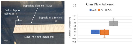
Figure 13.
(a) Printed element on glass plate (PLA shown) and (b) minimum printed distance needed for adhesion to glass plate.
3.2.2. Minimum Element Corner Radius
To identify the minimum corner radius possible with the FDM, a 25-mm square film consisting of two printed layers and a single shell printed at 50 mm/s was examined under a microscope. Each corner of each film was examined, for a total of four observations for each material. The results are shown in Figure 14; it was observed for all cases that the corner radii were approximately the same size as the nozzle radii; therefore, a reasonable conclusion is that the lower limit of corner radii is the width of the extrusion nozzle. The element width was mm and height was mm.
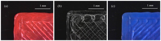
Figure 14.
Example corners for printed samples of (a) ABS, (b) PC, and (c) PLA.
3.2.3. Minimum Element Length on Previous Material
A single thin wall, 25-mm high and wide, was printed to estimate the minimum length of adhesion between the deposited and previously printed material. In all cases, the adhesion was excellent and any observed error was much smaller than the nozzle with (Figure 14). The element width was mm and height was mm.
From the presented cases (Figure 15), it is reasonable to conclude that setting the minimum polymer–polymer contact length as the nozzle width would give a conservative constraint. For the specific materials here, a value 0.10–0.25 times the nozzle width would also likely be a valid constraint.
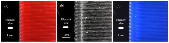
Figure 15.
Edge samples to estimate the gap (if any) at the end of each layer of (a) ABS, (b) PC, and (c) PLA.
3.2.4. Maximum Element Bridge Distance
The maximum element bridge distance was estimated using the geometry shown in Figure 16a, where the gap varied from 1 mm to 10 mm in 1-mm increments. Two different print speeds were used (10 mm/s and 50 mm/s) for each material. The bridge length was examined in several studies, which were reviewed in Table 5 in order to compare with the results found here. Note the very wide variance between materials, even when controlling for the print speed. As seen in Figure 16, the longest stable bridge was taken as the maximum approximate bridge length for that material/speed combination.
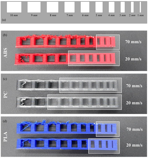
Figure 16.
Bridge length test setup and results. (a) Sample geometry, (b) results for ABS, (c) results for PC, and (d) results for PLA.
Table 5.
Some reported bridge lengths from the FDM literature compared with results found in this work. Note that only PLA-based studies were found in the literature, while studies for all three materials under consideration were completed.
3.2.5. Dimensional Error
To find the expected dimensional error, a dataset published previously by the author and colleagues [8,114] was analyzed (Figure 17). Note that this data analysis is new and was not part of the original studies that reported the dataset. It was based on the measurement of ASTM-specified IZOD testing samples, with the nominal Z, C, and E dimensions coming from ASTM-D256-10(2018) (Figure 17). Note that the printing parameters were slightly different (most importantly, the element width was mm with a height of mm) from what is used elsewhere in this paper, but it is assumed that the error between what is reported in this study and the current conditions is trivial; see the discussion on sensitivity analysis later in this paper. For the three materials examined, the observed errors (both raw and root mean squared (RMS) error) were equal to or smaller than the nozzle size.
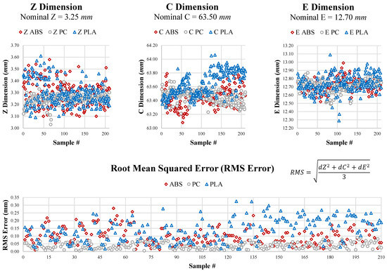
Figure 17.
True vs. nominal dimensions for Z, C, and E as well as the root mean squared error [8,114].
3.3. Sensitivity Analysis
In this sensitivity analysis (Table 6), the assumptions and simplifications from Table 4 and elsewhere in this work are formally laid out. In each case, the consequences and impact of a particular assumption or simplification being incorrect or poor is presented.
Table 6.
Sensitivity analysis on assumptions for the presented constraint set to be applied to the work in this paper. If a mitigation strategy has been put in place for the work presented, it will be specified in the table. If not (mitigation not needed or not possible), the entry for that assumption will be “None”.
4. Case Studies
4.1. Case Study 1: 2.5D Designs with Stable Features
The first case study explores three simple problems (Figure 18) that could be represented as 2-D or 2.5-D (2-D + thickness) design representations subject to the constraints developed in this paper. In the first case, (Designs 1a and 1b), a simple fan cover was designed with manually laid out features. For Design 1a, a deposition nozzle of w = 0.4 mm was used with a layer thickness of h = 0.2 mm (h/w = 0.5), with each of the thicker features being two elements wide for stability and one element wide for the smaller features. For design 1b, a nozzle of w = 1.0 mm (h/w = 0.2) was used, with resulting changes in the design.
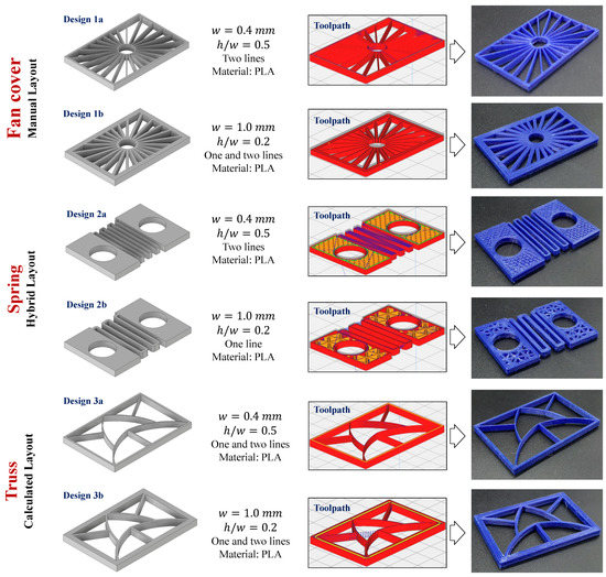
Figure 18.
Results of Case Study 1.
In the case of Design 2, a hybrid design method was used, with the spring coil being manually laid out and the infill for the solid area being calculated and laid out in a series of triangles. The last problem dealt with a truss, where the layout could be calculated in response to a specific mechanical problem. This case study demonstrated that the imposition of effective constraints on the parameters heavily influenced the designs. In addition, it showed that all of the constrained designs, regardless of complexity, were manufacturable on the first attempt.
4.2. Case Study 2: Designed Infill Geometry in Defined Space
In this case study, the computational layout of a 20-mm cubic shell with a low-density designed core was generated using Ultimaker Cura from PLA. All of the FDM constraints generated in this paper were applied to ensure manufacturability, even on areas with bridges and very thin features. In addition to the objectives (lay out the elements efficiently based on inputs) and constraints, the major design inputs to the software tool were:
- The geometry within the shell was only allowed to be a single element thick, so the designed core only presented one level of designable mesostructure;
- The deposition nozzle used was 0.5 mm in diameter and the deposition width was defined as 0.505 mm to account for material shrinkage. This setting was found to be the best for the transparent PLA used in the study after several trials;
- The w/h ratio was selected to be 5/2. An overlap setting was not needed, since the designed area was only allowed to be one element thick.
Four basic layouts were selected, specifically 3D cross, quarter cubic, gyroid, and standard raster lines. Figure 19 shows the layouts for Layer 10, Layer 25, Layer 50, and Layer 90 for each of the cases. Only the gyroid contained an unsupported bridge, so a maximum unsupported bridge length was set at 3 mm (see Section 3.2.4) before the design generation. Since it was impractical to use support material for these designs, this was used to limit the size of the gyroid elements. The layouts were driven by the requirement that the 3-D cross and quarter cubic cases were to occupy a total of 10% of the open space, the gyroid was to be close to 15% dense with the bridge requirement (so the density is slightly higher), and the elements in raster case were to have a diagonal (corner-to-corner) length of approximately 4 mm. Note that all of the cases could easily have been printed without the outer shell (or had the shell removed after printing). Including the shell was a design choice, as the concept could be explored with or without the shell. This case study did not solve a specific design problem and was focused on demonstrating that that the designed structures (with several different layouts, including those that varied significantly between layers) could be accurately manufactured, since the design parameters were based on the mechanics of the selected process. As shown in Figure 19, the manufacturing was successful, with no significant manufacturing defects noted upon examination under a microscope.
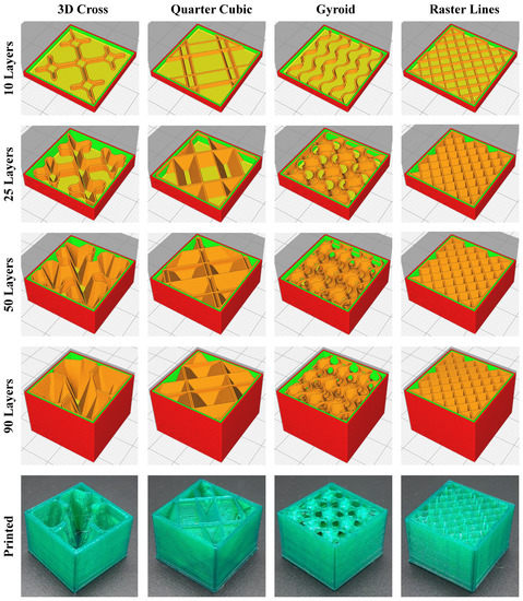
Figure 19.
Results of Case Study 2.
4.3. Case Study 3: Minimal Surfaces with Second Mesostructure
In this case study, the design of two mesostructure levels is explored for two basic minimal surfaces (gyroid—a triply-periodic surface and a Scherk tower—a singly-periodic structure) which are given a wall thickness. The internal structure (the lower mesostructure level) for each case is designed the same way as described in Case Study 2.
In these cases, the gyroid (defined within a 125-mm cubic design space) is given a wall thickness of 5 mm, while the Scherk surface is given a wall thickness of 2 mm and calculated within a design space with a 50-mm square base and 160-mm height (Figure 20). The basic surface figures, generating functions, and Matlab code for generating the surfaces came from a technical report on generating minimal surface models by Muna & Patterson [115]. There are numerous ways to translate the surface model into a solid STL file, the best of which is to use the surf2solid tool in Matlab with the surface generation code published in [115]. The functions used to generate the minimal surfaces were:
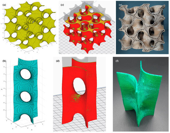
Figure 20.
Case Study 3. (a) Mathematical model of the gyroid, (b) mathematical model of the Scherk surface, (c) g-code for final gyroid model, (d) g-code for final Scherk surface model, and (e–f) successfully manufactured designs.
Example surfaces are shown in Figure 20a,b, while the g-code for the generated surfaces for this case study can be seen in Figure 20c,d. Partial prints (to show the internal mesostructure) of each can be seen the last two panels of the figure. Both were printed from PLA using FDM and used the same settings as Case Study 1, with the exception that the Scherk surface was printed at nearly 100% density (so only natural voids determined meso-scale properties). In this case, the internal mesostructure was a series of concentric rings. The internal mesostructure for the gyroid (clearly seen in Figure 20e), was identical to that of the raster case in Case Study 2, with the exception that the diagonal dimension of the resulting squares was 5 mm.
5. Closing Remarks
In this article, the manufacturability constraints for the fused deposition modeling (FDM) process are mapped, defined, refined, and presented. While some of the constraints and parameters presented here may be somewhat idealized, this is best for developing a good design perspective on the process as it requires much less technical background knowledge and expertise to understand and used.
The results of the mapping and constraint generation were carefully tabulated and presented in such a way that the are useful for a variety of design problems. Whether using classic design-for-manufacturing or one of the more modern approaches, these constraints will aid in problem formulation and process understanding. Having well-defined manufacturability constraints will aid designers in making good decisions, which will result in higher-quality designs with a much lower risk of design-process mismatch. Careful definition of the process in terms of it manufacturability constraints will also help anyone using the process for design or manufacturing to better understand its capabilities, limitations, and the best practices for using it.
Author Contributions
Conceptualization (A.E.P. and C.C.); derivation of the manufacturability constraints (Table 3 and Table 4) (A.E.P.); case studies (A.E.P. and C.C.); supervision and guidance on topics and corrections to mapping and definition issues (I.M.J.). All authors have read and agreed to the published version of the manuscript.
Funding
This research received no external funding.
Institutional Review Board Statement
Not Applicable.
Informed Consent Statement
Not Applicable.
Data Availability Statement
Any raw data associated with this work may be obtained upon request to the corresponding author.
Acknowledgments
The authors gratefully acknowledge the contributions, advice, direction, and feedback from the following people on this concept paper: Tais Rocha Pereira (help with process modeling and lead of dimensional accuracy study), Sherri Messimer (extensive advice on realistic FDM constraints and assumptions and help with dimensional accuracy study), James T. Allison (help with process modeling and understanding of system dynamics, which helped drive some of the constraint mapping as well as helpful discussion on the sensitivity analysis for major assumptions), and Nasiha Muna (help with developing Case Study 3).
Conflicts of Interest
The authors declare no conflict of interest.
References
- Gholamipour-Shirazi, A.; Kamlow, M.A.; Norton, I.T.; Mills, T. How to Formulate for Structure and Texture via Medium of Additive Manufacturing—A Review. Foods 2020, 9, 497. [Google Scholar] [CrossRef]
- Tanner, J.A.; Jethwa, B.; Jackson, J.; Bartanuszova, M.; King, T.S.; Bhattacharya, A.; Sharma, R. A Three-Dimensional Print Model of the Pterygopalatine Fossa Significantly Enhances the Learning Experience. Anat. Sci. Educ. 2020, 13, 568–580. [Google Scholar] [CrossRef]
- Velázquez, J.S.; Cavas, F.; Bolarín, J.M.; Alió, J.L. 3D Printed Personalized Corneal Models as a Tool for Improving Patient’s Knowledge of an Asymmetric Disease. Symmetry 2020, 12, 151. [Google Scholar] [CrossRef]
- Mohamed, O.A.; Masood, S.H.; Bhowmik, J.L. Experimental Investigations of Process Parameters Influence on Rheological Behavior and Dynamic Mechanical Properties of FDM Manufactured Parts. Mater. Manuf. Process. 2015, 31, 1983–1994. [Google Scholar] [CrossRef]
- Mohamed, O.A.; Masood, S.H.; Bhowmik, J.L. Optimization of fused deposition modeling process parameters for dimensional accuracy using I-optimality criterion. Measurement 2016, 81, 174–196. [Google Scholar] [CrossRef]
- Turner, B.N.; Gold, S.A. A review of melt extrusion additive manufacturing processes: II. Materials, dimensional accuracy, and surface roughness. Rapid Prototyp. J. 2015, 21, 250–261. [Google Scholar] [CrossRef]
- Turner, B.N.; Strong, R.; Gold, S.A. A review of melt extrusion additive manufacturing processes: I. Process design and modeling. Rapid Prototyp. J. 2014, 20, 192–204. [Google Scholar] [CrossRef]
- Messimer, S.; Pereira, T.; Patterson, A.; Lubna, M.; Drozda, F. Full-Density Fused Deposition Modeling Dimensional Error as a Function of Raster Angle and Build Orientation: Large Dataset for Eleven Materials. J. Manuf. Mater. Process. 2019, 3, 6. [Google Scholar] [CrossRef]
- Hongyao, S.; Xiaoxiang, Y.; Jianzhong, F. Research on the flexible support platform for fused deposition modeling. Int. J. Adv. Manuf. Technol. 2018, 97, 3205–3221. [Google Scholar] [CrossRef]
- Kim, C.; Espalin, D.; Cuaron, A.; Perez, M.A.; MacDonald, E.; Wicker, R.B. A study to detect a material deposition status in fused deposition modeling technology. In Proceedings of the 2015 IEEE International Conference on Advanced Intelligent Mechatronics (AIM), Busan, Korea, 7–11 July 2015. [Google Scholar] [CrossRef]
- Wang, Y.; Huang, J.; Wang, Y.; Feng, S.; Peng, T.; Yang, H.; Zou, J. A CNN-Based Adaptive Surface Monitoring System for Fused Deposition Modeling. IEEE/ASME Trans. Mechatron. 2020, 25, 2287–2296. [Google Scholar] [CrossRef]
- Ahn, S.H.; Montero, M.; Odell, D.; Roundy, S.; Wright, P.K. Anisotropic material properties of fused deposition modeling ABS. Rapid Prototyp. J. 2002, 8, 248–257. [Google Scholar] [CrossRef]
- Gardan, J.; Makke, A.; Recho, N. A method to improve the fracture toughness using 3D printing by extrusion deposition. Procedia Struct. Integr. 2016, 2, 144–151. [Google Scholar] [CrossRef]
- Gardan, J. Method for characterization and enhancement of 3D printing by binder jetting applied to the textures quality. Assem. Autom. 2017, 37, 162–169. [Google Scholar] [CrossRef]
- Alafaghani, A.; Qattawi, A.; Alrawi, B.; Guzman, A. Experimental Optimization of Fused Deposition Modelling Processing Parameters: A Design-for-Manufacturing Approach. Procedia Manuf. 2017, 10, 791–803. [Google Scholar] [CrossRef]
- Rezaie, R.; Badrossamay, M.; Ghaie, A.; Moosavi, H. Topology Optimization for Fused Deposition Modeling Process. Procedia CIRP 2013, 6, 521–526. [Google Scholar] [CrossRef]
- Abeykoon, C.; Sri-Amphorn, P.; Fernando, A. Optimization of fused deposition modeling parameters for improved PLA and ABS 3D printed structures. Int. J. Lightweight Mater. Manuf. 2020, 3, 284–297. [Google Scholar] [CrossRef]
- Ahmed, A.; Susmel, L. Additively Manufactured PLA under static loading: Strength/cracking behaviour vs. deposition angle. Procedia Struct. Integr. 2017, 3, 498–507. [Google Scholar] [CrossRef]
- Alafaghani, A.; Qattawi, A. Investigating the effect of fused deposition modeling processing parameters using Taguchi design of experiment method. J. Manuf. Process. 2018, 36, 164–174. [Google Scholar] [CrossRef]
- Álvarez, K.; Lagos, R.F.; Aizpun, M. Investigating the influence of infill percentage on the mechanical properties of fused deposition modelled ABS parts. Ingeniería e Investigación 2016, 36, 110. [Google Scholar] [CrossRef]
- Carneiro, O.; Silva, A.; Gomes, R. Fused deposition modeling with polypropylene. Mater. Des. 2015, 83, 768–776. [Google Scholar] [CrossRef]
- Cerda-Avila, S.N.; Medellín-Castillo, H.I.; de Lange, D.F. Analysis and Numerical Simulation of the Structural Performance of Fused Deposition Modeling Samples with Variable Infill Values. J. Eng. Mater. Technol. 2018, 141. [Google Scholar] [CrossRef]
- Dave, H.K.; Patadiya, N.H.; Prajapati, A.R.; Rajpurohit, S.R. Effect of infill pattern and infill density at varying part orientation on tensile properties of fused deposition modeling-printed poly-lactic acid part. Proc. Inst. Mech. Eng. Part C J. Mech. Eng. Sci. 2019, 095440621985638. [Google Scholar] [CrossRef]
- Dey, A.; Hoffman, D.; Yodo, N. Optimizing multiple process parameters in fused deposition modeling with particle swarm optimization. Int. J. Interact. Des. Manuf. (IJIDeM) 2019, 14, 393–405. [Google Scholar] [CrossRef]
- Durão, L.F.C.S.; Barkoczy, R.; Zancul, E.; Ho, L.L.; Bonnard, R. Optimizing additive manufacturing parameters for the fused deposition modeling technology using a design of experiments. Prog. Addit. Manuf. 2019, 4, 291–313. [Google Scholar] [CrossRef]
- Gebisa, A.; Lemu, H. Investigating Effects of Fused-Deposition Modeling (FDM) Processing Parameters on Flexural Properties of ULTEM 9085 using Designed Experiment. Materials 2018, 11, 500. [Google Scholar] [CrossRef] [PubMed]
- Hossain, M.S.; Espalin, D.; Ramos, J.; Perez, M.; Wicker, R. Improved Mechanical Properties of Fused Deposition Modeling-Manufactured Parts Through Build Parameter Modifications. J. Manuf. Sci. Eng. 2014, 136. [Google Scholar] [CrossRef]
- Huang, B.; Meng, S.; He, H.; Jia, Y.; Xu, Y.; Huang, H. Study of processing parameters in fused deposition modeling based on mechanical properties of acrylonitrile-butadiene-styrene filament. Polym. Eng. Sci. 2018, 59, 120–128. [Google Scholar] [CrossRef]
- Khaleeq uz Zaman, U.; Boesch, E.; Siadat, A.; Rivette, M.; Baqai, A.A. Impact of fused deposition modeling (FDM) process parameters on strength of built parts using Taguchi’s design of experiments. Int. J. Adv. Manuf. Technol. 2018, 101, 1215–1226. [Google Scholar] [CrossRef]
- Khatri, A.; Adnan, A. Effect of Raster Orientation on Fracture Toughness Properties of 3D Printed Abs Materials and Structures. Volume 9: Mechanics of Solids, Structures and Fluids; NDE, Diagnosis, and Prognosis; American Society of Mechanical Engineers: New York, NY, USA, 2016. [Google Scholar] [CrossRef]
- Lanzillotti, P.; Gardan, J.; Makke, A.; Recho, N. Strengthening in fracture toughness of a smart material manufactured by 3D printing. IFAC Pap. 2018, 51, 1353–1358. [Google Scholar] [CrossRef]
- Lyu, J.; Manoochehri, S. Modeling Machine Motion and Process Parameter Errors for Improving Dimensional Accuracy of Fused Deposition Modeling Machines. J. Manuf. Sci. Eng. 2018, 140. [Google Scholar] [CrossRef]
- McLouth, T.D.; Severino, J.V.; Adams, P.M.; Patel, D.N.; Zaldivar, R.J. The impact of print orientation and raster pattern on fracture toughness in additively manufactured ABS. Addit. Manuf. 2017, 18, 103–109. [Google Scholar] [CrossRef]
- Ning, F.; Cong, W.; Hu, Y.; Wang, H. Additive manufacturing of carbon fiber-reinforced plastic composites using fused deposition modeling: Effects of process parameters on tensile properties. J. Compos. Mater. 2016, 51, 451–462. [Google Scholar] [CrossRef]
- Padhi, S.K.; Sahu, R.K.; Mahapatra, S.S.; Das, H.C.; Sood, A.K.; Patro, B.; Mondal, A.K. Optimization of fused deposition modeling process parameters using a fuzzy inference system coupled with Taguchi philosophy. Adv. Manuf. 2017, 5, 231–242. [Google Scholar] [CrossRef]
- Patterson, A.E.; Pereira, T.R.; Allison, J.T.; Messimer, S.L. IZOD impact properties of full-density fused deposition modeling polymer materials with respect to raster angle and print orientation. Proc. Inst. Mech. Eng. Part C J. Mech. Eng. Sci. 2019, 095440621984038. [Google Scholar] [CrossRef]
- Peng, A.; Xiao, X.; Yue, R. Process parameter optimization for fused deposition modeling using response surface methodology combined with fuzzy inference system. Int. J. Adv. Manuf. Technol. 2014, 73, 87–100. [Google Scholar] [CrossRef]
- Pérez, M.; Medina-Sánchez, G.; García-Collado, A.; Gupta, M.; Carou, D. Surface Quality Enhancement of Fused Deposition Modeling (FDM) Printed Samples Based on the Selection of Critical Printing Parameters. Materials 2018, 11, 1382. [Google Scholar] [CrossRef]
- Rahman, K.M.; Letcher, T.; Reese, R. Mechanical Properties of Additively Manufactured PEEK Components Using Fused Filament Fabrication. Volume 2A: Advanced Manufacturing; American Society of Mechanical Engineers: New York, NY, USA, 2015. [Google Scholar] [CrossRef]
- Rao, R.V.; Rai, D.P. Optimization of fused deposition modeling process using teaching-learning-based optimization algorithm. Eng. Sci. Technol. Int. J. 2016, 19, 587–603. [Google Scholar] [CrossRef]
- Vicente, C.M.; Martins, T.S.; Leite, M.; Ribeiro, A.; Reis, L. Influence of fused deposition modeling parameters on the mechanical properties of ABS parts. Polym. Adv. Technol. 2019, 31, 501–507. [Google Scholar] [CrossRef]
- Wang, P.; Zou, B.; Xiao, H.; Ding, S.; Huang, C. Effects of printing parameters of fused deposition modeling on mechanical properties, surface quality, and microstructure of PEEK. J. Mater. Process. Technol. 2019, 271, 62–74. [Google Scholar] [CrossRef]
- Zhang, J.W.; Peng, A.H. Process-Parameter Optimization for Fused Deposition Modeling Based on Taguchi Method. Adv. Mater. Res. 2012, 538–541, 444–447. [Google Scholar] [CrossRef]
- Papalambros, P.Y.; Wilde, D.J. Principles of Optimal Design: Modeling and Computation, 2nd ed.; Cambridge University Press: Cambridge, UK, 2000. [Google Scholar]
- Andrei, N. An unconstrained optimization test function collection. Adv. Model. Optim. 2008, 10, 147–161. [Google Scholar]
- Gill, P.E.; Murray, W. Quasi-Newton Methods for Unconstrained Optimization. IMA J. Appl. Math. 1972, 9, 91–108. [Google Scholar] [CrossRef]
- Morris, N.; Butscher, A.; Iorio, F. A subtractive manufacturing constraint for level set topology optimization. Struct. Multidiscip. Optim. 2020, 61, 1573–1588. [Google Scholar] [CrossRef]
- Vatanabe, S.L.; Lippi, T.N.; de Lima, C.R.; Paulino, G.H.; Silva, E.C. Topology optimization with manufacturing constraints: A unified projection-based approach. Adv. Eng. Softw. 2016, 100, 97–112. [Google Scholar] [CrossRef]
- Carstensen, J.V. Topology optimization with nozzle size restrictions for material extrusion-type additive manufacturing. Struct. Multidiscip. Optim. 2020, 62, 2481–2497. [Google Scholar] [CrossRef]
- Sutradhar, A.; Park, J.; Haghighi, P.; Kresslein, J.; Detwiler, D.; Shah, J.J. Incorporating Manufacturing Constraints in Topology Optimization Methods: A Survey. In Proceedings of the 37th Computers and Information in Engineering Conference, Cleveland, OH, USA, 6–9 August 2017; Volume 1. [Google Scholar] [CrossRef]
- Lutters, E.; van Houten, F.J.; Bernard, A.; Mermoz, E.; Schutte, C.S. Tools and techniques for product design. CIRP Ann. 2014, 63, 607–630. [Google Scholar] [CrossRef]
- Bralla, J.G. Design for Manufacturability Handbook, 2nd ed.; McGraw-Hill Education: New York, NY, USA, 1998. [Google Scholar]
- ElMaraghy, W.; ElMaraghy, H.; Tomiyama, T.; Monostori, L. Complexity in engineering design and manufacturing. CIRP Ann. 2012, 61, 793–814. [Google Scholar] [CrossRef]
- Blanchard, B.S.; Fabrycky, W.J. Systems Engineering and Analysis, 4th ed.; Prentice Hall: Hoboken, NJ, USA, 2005. [Google Scholar]
- Patterson, A.E.; Allison, J.T. Manufacturability Constraint Formulation for Design Under Hybrid Additive-Subtractive Manufacturing. In Proceedings of the 23rd Design for Manufacturing and the Life Cycle Conference, Quebec City, QC, Canada, 26–29 August 2018; Volume 4. [Google Scholar] [CrossRef]
- Patterson, A.E.; Allison, J.T. Generation and Mapping of Minimally-Restrictive Manufacturability Constraints for Mechanical Design Problems. In Proceedings of the 24th Design for Manufacturing and the Life Cycle Conference; 13th International Conference on Micro- and Nanosystems, Anaheim, CA, USA, 18–21 August 2019; Volume 4. [Google Scholar] [CrossRef]
- Patterson, A.E.; Lee, Y.H.; Allison, J.T. Overview of the Development and Enforcement of Process-Driven Manufacturability Constraints in Product Design. In Proceedings of the 24th Design for Manufacturing and the Life Cycle Conference; 13th International Conference on Micro- and Nanosystems, Anaheim, CA, USA, 18–21 August 2019; Volume 4. [Google Scholar] [CrossRef]
- Borgue, O.; Müller, J.; Leicht, A.; Panarotto, M.; Isaksson, O. Constraint Replacement-Based Design for Additive Manufacturing of Satellite Components: Ensuring Design Manufacturability through Tailored Test Artefacts. Aerospace 2019, 6, 124. [Google Scholar] [CrossRef]
- Borgue, O.; Valjak, F.; Panarotto, M.; Isaksson, O. Supporting additive manufacturing technology development through constraint modeling in early conceptual design: A satellite propulsion case study. Proc. Des. Soc. Des. Conf. 2020, 1, 817–826. [Google Scholar] [CrossRef]
- Müller, J.R.; Borgue, O.; Panarotto, M.; Isaksson, O. Mapping the design space in function and geometry models supporting redesign for additive manufacturing. J. Des. Res. 2020, 18, 37. [Google Scholar] [CrossRef]
- Black, J.T.; Kohser, R.A. DeGarmo’s Materials and Processes in Manufacturing, 11th ed.; Wiley: Hoboken, NJ, USA, 2011. [Google Scholar]
- Gardan, J.; Makke, A.; Recho, N. Improving the fracture toughness of 3D printed thermoplastic polymers by fused deposition modeling. Int. J. Fract. 2017, 210, 1–15. [Google Scholar] [CrossRef]
- Cattenone, A.; Morganti, S.; Alaimo, G.; Auricchio, F. Finite Element Analysis of Additive Manufacturing Based on Fused Deposition Modeling: Distortions Prediction and Comparison With Experimental Data. J. Manuf. Sci. Eng. 2018, 141. [Google Scholar] [CrossRef]
- Bellini, A.; Güceri, S.; Bertoldi, M. Liquefier Dynamics in Fused Deposition. J. Manuf. Sci. Eng. 2004, 126, 237–246. [Google Scholar] [CrossRef]
- Shadvar, N.; Foroozmehr, E.; Badrossamay, M.; Amouhadi, I.; Dindarloo, A.S. Computational analysis of the extrusion process of fused deposition modeling of acrylonitrile-butadiene-styrene. Int. J. Mater. Form. 2019. [Google Scholar] [CrossRef]
- Srinivas, V.; van Hooy-Corstjens, C.S.; Harings, J.A. Correlating molecular and crystallization dynamics to macroscopic fusion and thermodynamic stability in fused deposition modeling: A model study on polylactides. Polymer 2018, 142, 348–355. [Google Scholar] [CrossRef]
- Coogan, T.J.; Kazmer, D.O. In-line rheological monitoring of fused deposition modeling. J. Rheol. 2019, 63, 141–155. [Google Scholar] [CrossRef]
- Zhang, J.; Wang, X.Z.; Yu, W.W.; Deng, Y.H. Numerical investigation of the influence of process conditions on the temperature variation in fused deposition modeling. Mater. Des. 2017, 130, 59–68. [Google Scholar] [CrossRef]
- Zhou, Y.; Nyberg, T.; Xiong, G.; Liu, D. Temperature Analysis in the Fused Deposition Modeling Process. In Proceedings of the 2016 3rd International Conference on Information Science and Control Engineering (ICISCE), Beijing, China, 8–10 July 2016. [Google Scholar] [CrossRef]
- Zhang, Y.; Shapiro, V. Linear-Time Thermal Simulation of As-Manufactured Fused Deposition Modeling Components. J. Manuf. Sci. Eng. 2018, 140. [Google Scholar] [CrossRef]
- Bellehumeur, C.; Li, L.; Sun, Q.; Gu, P. Modeling of Bond Formation Between Polymer Filaments in the Fused Deposition Modeling Process. J. Manuf. Process. 2004, 6, 170–178. [Google Scholar] [CrossRef]
- Costa, S.; Duarte, F.; Covas, J. Estimation of filament temperature and adhesion development in fused deposition techniques. J. Mater. Process. Technol. 2017, 245, 167–179. [Google Scholar] [CrossRef]
- Kim, Y.; Alcantara, D.; Zohdi, T.I. Thermal state estimation of fused deposition modeling in additive manufacturing processes using Kalman filters. Int. J. Numer. Methods Eng. 2020. [Google Scholar] [CrossRef]
- Messimer, S.L.; Patterson, A.E.; Muna, N.; Deshpande, A.P.; Pereira, T.R. Characterization and Processing Behavior of Heated Aluminum-Polycarbonate Composite Build Plates for the FDM Additive Manufacturing Process. J. Manuf. Mater. Process. 2018, 2, 12. [Google Scholar] [CrossRef]
- Rodríguez, J.F.; Thomas, J.P.; Renaud, J.E. Mechanical behavior of acrylonitrile butadiene styrene fused deposition materials modeling. Rapid Prototyp. J. 2003, 9, 219–230. [Google Scholar] [CrossRef]
- Shofner, M.; Rodriguez-Macias, F.; Vaidyanathan, R.; Barrera, E. Single wall nanotube and vapor grown carbon fiber reinforced polymers processed by extrusion freeform fabrication. Compos. Part A Appl. Sci. Manuf. 2003, 34, 1207–1217. [Google Scholar] [CrossRef]
- Alaimo, G.; Marconi, S.; Costato, L.; Auricchio, F. Influence of meso-structure and chemical composition on FDM 3D-printed parts. Compos. Part B Eng. 2017, 113, 371–380. [Google Scholar] [CrossRef]
- Levenhagen, N.P.; Dadmun, M.D. Interlayer diffusion of surface segregating additives to improve the isotropy of fused deposition modeling products. Polymer 2018, 152, 35–41. [Google Scholar] [CrossRef]
- Lin, S.; Xia, L.; Ma, G.; Zhou, S.; Xie, Y.M. A maze-like path generation scheme for fused deposition modeling. Int. J. Adv. Manuf. Technol. 2019, 104, 1509–1519. [Google Scholar] [CrossRef]
- Bellini, A.; Güçeri, S. Mechanical characterization of parts fabricated using fused deposition modeling. Rapid Prototyp. J. 2003, 9, 252–264. [Google Scholar] [CrossRef]
- Gordeev, E.G.; Galushko, A.S.; Ananikov, V.P. Improvement of quality of 3D printed objects by elimination of microscopic structural defects in fused deposition modeling. PLoS ONE 2018, 13, e0198370. [Google Scholar] [CrossRef]
- Nadiyapara, H.H.; Pande, S. A Review of Variable Slicing in Fused Deposition Modeling. J. Inst. Eng. Ser. C 2016, 98, 387–393. [Google Scholar] [CrossRef]
- Balta, E.C.; Tilbury, D.M.; Barton, K. Control-Oriented Modeling and Layer-to-Layer Stability for Fused Deposition Modeling: A Kernel Basis Approach. In Proceedings of the 2019 American Control Conference (ACC), Philadelphia, PA, USA, 10–12 July 2019. [Google Scholar] [CrossRef]
- Aksoy, D.; Balta, E.C.; Tilbury, D.M.; Barton, K. A Control-Oriented Model for Bead Cross-Sectional Geometry in Fused Deposition Modeling. In Proceedings of the 2020 American Control Conference (ACC), Denver, CO, USA, 1–3 July 2020. [Google Scholar] [CrossRef]
- Prabhu, R.; Devaraju, A. Recent review of tribology, rheology of biodegradable and FDM compatible polymers. Mater. Today Proc. 2020. [Google Scholar] [CrossRef]
- Pradel, P.; Zhu, Z.; Bibb, R.; Moultrie, J. A framework for mapping design for additive manufacturing knowledge for industrial and product design. J. Eng. Des. 2018, 29, 291–326. [Google Scholar] [CrossRef]
- Adam, G.A.; Zimmer, D. Design for Additive Manufacturing—Element transitions and aggregated structures. CIRP J. Manuf. Sci. Technol. 2014, 7, 20–28. [Google Scholar] [CrossRef]
- Adam, G.A.O.; Zimmer, D. On design for additive manufacturing: Evaluating geometrical limitations. Rapid Prototyp. J. 2015, 21, 662–670. [Google Scholar] [CrossRef]
- Maidin, S.B.; Campbell, I.; Pei, E. Development of a design feature database to support design for additive manufacturing. Assem. Autom. 2012, 32, 235–244. [Google Scholar] [CrossRef]
- Thompson, M.K.; Moroni, G.; Vaneker, T.; Fadel, G.; Campbell, R.I.; Gibson, I.; Bernard, A.; Schulz, J.; Graf, P.; Ahuja, B.; et al. Design for Additive Manufacturing: Trends, opportunities, considerations, and constraints. CIRP Ann. 2016, 65, 737–760. [Google Scholar] [CrossRef]
- Liu, S.; Li, Q.; Chen, W.; Tong, L.; Cheng, G. An identification method for enclosed voids restriction in manufacturability design for additive manufacturing structures. Front. Mech. Eng. 2015, 10, 126–137. [Google Scholar] [CrossRef]
- Wittbrodt, B.; Pearce, J.M. The effects of PLA color on material properties of 3-D printed components. Addit. Manuf. 2015, 8, 110–116. [Google Scholar] [CrossRef]
- Arbeiter, F.; Spoerk, M.; Wiener, J.; Gosch, A.; Pinter, G. Fracture mechanical characterization and lifetime estimation of near-homogeneous components produced by fused filament fabrication. Polym. Test. 2018, 66, 105–113. [Google Scholar] [CrossRef]
- Allum, J.; Gleadall, A.; Silberschmidt, V.V. Fracture of 3D-printed polymers: Crucial role of filament-scale geometric features. Eng. Fract. Mech. 2020, 224, 106818. [Google Scholar] [CrossRef]
- Cicala, G.; Giordano, D.; Tosto, C.; Filippone, G.; Recca, A.; Blanco, I. Polylactide (PLA) Filaments a Biobased Solution for Additive Manufacturing: Correlating Rheology and Thermomechanical Properties with Printing Quality. Materials 2018, 11, 1191. [Google Scholar] [CrossRef] [PubMed]
- Jee, H.; Witherell, P. A method for modularity in design rules for additive manufacturing. Rapid Prototyp. J. 2017, 23, 1107–1118. [Google Scholar] [CrossRef]
- Yaman, U. Shrinkage compensation of holes via shrinkage of interior structure in FDM process. Int. J. Adv. Manuf. Technol. 2017, 94, 2187–2197. [Google Scholar] [CrossRef]
- Manmadhachary, A.; Kumar, Y.R.; Krishnanand, L. Finding of Correction Factor and Dimensional Error in Bio-AM Model by FDM Technique. J. Inst. Eng. Ser. C 2016, 99, 293–300. [Google Scholar] [CrossRef]
- Tong, K.; Joshi, S.; Lehtihet, E.A. Error compensation for fused deposition modeling (FDM) machine by correcting slice files. Rapid Prototyp. J. 2008, 14, 4–14. [Google Scholar] [CrossRef]
- Rahman, H.; John, T.; Sivadasan, M.; Singh, N. Investigation on the Scale Factor applicable to ABS based FDM Additive Manufacturing. Mater. Today Proc. 2018, 5, 1640–1648. [Google Scholar] [CrossRef]
- Liu, J.; Ma, Y.; Qureshi, A.J.; Ahmad, R. Light-weight shape and topology optimization with hybrid deposition path planning for FDM parts. Int. J. Adv. Manuf. Technol. 2018, 97, 1123–1135. [Google Scholar] [CrossRef]
- Rocha Pereira, T.; Patterson, A.E.; Messimer, S.L. Buckling Strength of 3-D Printed Thermoplastic Thin Shells: Notes on an Exploratory Study of As-Printed and Reinforced Cases. Appl. Sci. 2020, 10, 5863. [Google Scholar] [CrossRef]
- Skawiński, I.; Goetzendorf-Grabowski, T. FDM 3D printing method utility assessment in small RC aircraft design. Aircr. Eng. Aerosp. Technol. 2019, 91, 865–872. [Google Scholar] [CrossRef]
- Fu, X.; Zhang, X.; Huang, Z. Axial crushing of Nylon and Al/Nylon hybrid tubes by FDM 3D printing. Compos. Struct. 2021, 256, 113055. [Google Scholar] [CrossRef]
- Pal, K.; Panwar, V.; Friedrich, S.; Gehde, M. An Investigation on Vibration Welding of Amorphous and Semicrystalline Polymers. Mater. Manuf. Process. 2015, 31, 372–378. [Google Scholar] [CrossRef]
- Dundar, M.A.; Dhaliwal, G.S. Investigation for impact behavior of acrylonitrile-butadiene-styrene amorphous thermoplastic. Polym. Test. 2020, 89, 106624. [Google Scholar] [CrossRef]
- Neki, K.; Geil, P.H. Morphology-property studies of amorphous polycarbonate. J. Macromol. Sci. Part B 1973, 8, 295–341. [Google Scholar] [CrossRef]
- Zoller, P. A study of the pressure-volume-temperature relationships of four related amorphous polymers: Polycarbonate, polyarylate, phenoxy, and polysulfone. J. Polym. Sci. Polym. Phys. Ed. 1982, 20, 1453–1464. [Google Scholar] [CrossRef]
- Fang, Q.; Hanna, M.A. Rheological properties of amorphous and semicrystalline polylactic acid polymers. Ind. Crops Prod. 1999, 10, 47–53. [Google Scholar] [CrossRef]
- Piorkowska, E.; Kulinski, Z.; Galeski, A.; Masirek, R. Plasticization of semicrystalline poly(l-lactide) with poly(propylene glycol). Polymer 2006, 47, 7178–7188. [Google Scholar] [CrossRef]
- Jiang, J.; Stringer, J.; Xu, X. Support Optimization for Flat Features via Path Planning in Additive Manufacturing. 3D Print. Addit. Manuf. 2019, 6, 171–179. [Google Scholar] [CrossRef]
- Jiang, J.; Xu, X.; Stringer, J. Optimization of process planning for reducing material waste in extrusion based additive manufacturing. Robot. Comput. Integr. Manuf. 2019, 59, 317–325. [Google Scholar] [CrossRef]
- Jiang, J.; Hu, G.; Li, X.; Xu, X.; Zheng, P.; Stringer, J. Analysis and prediction of printable bridge length in fused deposition modelling based on back propagation neural network. Virtual Phys. Prototyp. 2019, 14, 253–266. [Google Scholar] [CrossRef]
- Drozda, F.; Rocha Pereira, T.; Patterson, A. End-user manufacturing with FDM/FFF: Interfaces, tolerances, repeatability, and dimensional accuracy. In Proceedings of the 2020 Institute of Industrial and Systems Engineers (IISE) Annual Conference and Exhibition, Virtual Conference, 1–3 November 2020. [Google Scholar]
- Muna, N.; Patterson, A. Simple 3-D Visualization of Some Common Mathematical Minimal Surfaces Using MATLAB. Technical Report, IDEALS—University of Illinois at Urbana-Champaign. 2018. Available online: http://hdl.handle.net/2142/101899 (accessed on 3 January 2020).
Publisher’s Note: MDPI stays neutral with regard to jurisdictional claims in published maps and institutional affiliations. |
© 2021 by the authors. Licensee MDPI, Basel, Switzerland. This article is an open access article distributed under the terms and conditions of the Creative Commons Attribution (CC BY) license (https://creativecommons.org/licenses/by/4.0/).