Abstract
Lattice structures, inspired by the crystal lattice, are periodically arranged structures composed of rods and nodes, featuring buffering, energy absorption, and excellent thermal insulation properties. Five types of unit cell structures were tested and the diamond lattice structure exhibited relatively smoother stress–strain curve, and its compression failure process was more stable. The diamond lattice structure was then subjected to the quasi-static compression test at temperatures of −40 °C, 25 °C, 100 °C, and 170 °C. It was found that there is a significant plateau stress during compression, and the magnitude of this plateau stress can be adjusted by changing the rod diameter. Subsequently, its thermal insulation performance was tested, and it was found that as the rod diameter increases, the plateau stress increases, but the thermal insulation performance decreases. Therefore, when designing shock absorber filler materials, the relationship between plateau stress and thermal insulation performance should be balanced, and the parameters with the best comprehensive performance should be selected.
1. Introduction
Spent nuclear fuel, also known as irradiated nuclear fuel, is nuclear fuel that has been exposed to radiation and utilized. Typically, spent nuclear fuel is produced by nuclear power plants’ nuclear reactors. The treatment of spent nuclear fuel mainly includes storage, transportation, reprocessing, and deep geological disposal, among other processes. It is important to note that shock absorbers that prevent drop damage during transportation are important pieces of equipment in the transportation of spent nuclear fuel. The filler material inside the shock absorber should exhibit superior energy absorption and heat insulation properties.
The commonly used filler materials for shock absorbers include wood, polyurethane foam, and foam aluminum, among others. Shell-type shock absorbers that utilize wood as a filler material are a mature and widely used structural form. Typically, lightweight woods such as balsa, mahogany, pine, and spruce are chosen as buffer materials [1,2,3]. Although wood as a buffer material has the advantages of being lightweight and having good energy absorption, it also has inherent flaws such as anisotropy and poor resistance to moisture and heat [4]. Currently, experts and scholars are exploring various new alternative materials. Some spent fuel transport containers also utilize rigid polyurethane foam, honeycomb aluminum, and other engineering materials as buffer materials for shock absorbers [5,6,7,8]. In the United States, the T-3 type transport containers have shock absorbers at both ends made of low-carbon steel shells with an interior filled with rigid polyurethane foam material, which protects the ends of the container from structural impacts and thermal damage. The U.S. Hi-STAR100 spent fuel container primarily consists of a 304 stainless-steel shell and honeycomb aluminum as the buffer material, filled with unidirectional honeycomb aluminum material in areas that only undergo unidirectional impact loads. The Spanish ENUN 32 spent fuel transport container’s shock absorbers also employ a design that combines honeycomb material with polyurethane foam. However, currently, the use of these two filler materials is limited due to the low strength of polyurethane foam and the anisotropic buffering performance of honeycomb aluminum [9].
The lattice structure is a type of periodic arrangement structure inspired by the crystal lattice, composed of rods and nodes [10,11,12]. Due to its excellent energy absorption capacity and lightweight nature, it is widely used in industrial fields such as aerospace, transportation, and mechanical equipment. Wang et al. proposed a lattice structure with a negative Poisson’s ratio, placing it at the bottom of the aircraft cabin to simulate landing conditions during an emergency landing of an aircraft. Experimental results show that the concave hexagonal lattice structure has outstanding energy absorption performance [13]. Inspired by spider webs, Liang et al. [14] evenly distributed a three-dimensional lantern-shaped lattice structure at the bottom of new energy vehicle batteries. This can effectively prevent damage to the car battery from road debris while driving at high speeds. Shen et al. [15] compared the quasi-static and low-speed impact behavior of stainless steel/titanium alloy lattice, aluminum honeycomb, and aluminum foam reinforced sandwich panels. The results indicate that the lattice sandwich panel has superior impact resistance compared to the honeycomb core sandwich panel. Yao et al. [16,17] proposed an arched lattice structure based on the characteristics of a high-strength load-bearing arch structure and conducted research on its quasi-static compression and high-speed impact performance. It has been confirmed that its load-bearing capacity is higher than that of conventional lattice structures such as BCC and FCC. Many researchers have proposed different types of lattice structures, applied to helmet linings, engine covers, anti-impact hydraulic supports, lander footpads, car anti-collision beams, energy absorption boxes, and blast-resistant sandwich panels [18,19,20]. Seong Je Park et al. pointed out that mixed lattice structures can effectively overcome the energy absorption limitations of single lattice structures, proving that mixed lattice structures have great potential for applications [21]. Panagiotis Stavropoulos and Panagis Foteinopoulos pointed out the key issues in additive manufacturing, providing excellent guidance for researchers [22].
The internal filling of the lattice structure demonstrates that its performance is particularly noteworthy and widely applicable, making it a focal point of research in the field of energy-absorbing structures. The density and plateau stress values of existing lattice structures are summarized in Table 1. China Nuclear Power Engineering Co., Ltd. (Beijing, China). has provided preliminary design requirements, with a density of filling material ≤1 g/m3 and adjustable plateau stress in the range of 5–40 MPa. Therefore, it is necessary to find a lattice structure with an actual density of less than 1 g/cm3 and a plateau stress of 5–40 MPa, where the plateau stress is relatively smooth.

Table 1.
Density and plateau stress of different types of lattice structure.
It is evident that lattice structures with excellent damping performance are expected to become a novel type of filler material with high designability for shock absorbers used in the transportation of spent nuclear fuel. This study selected Ti-6AL-4V as the main material for the filler structure of the shock absorber for transporting spent nuclear fuel, considering factors such as weight, cost, and mechanical properties. The structures are manufactured using Selective Laser Melting (SLM), and the type of lattice structure chosen is diamond-shaped based on quasi-static compression tests. Finally, the load-bearing and thermal insulation performances of the Ti-6AL-4V diamond-shaped lattice structure are tested. Firstly, through actual compression testing, the TC4 material diamond lattice structure was selected as the type of lattice structure with relatively smooth plateau stress. Then, the plateau stress of the diamond lattice structures with different strut diameters was calculated through finite element simulation. Subsequently, actual compression tests were conducted on diamond lattice structures with different strut diameters, and compression stress–strain curves were obtained. The simulated average plateau stress was compared with the actual tested average plateau stress. Finally, the thermal insulation performance of diamond lattice structures with different rod diameters was tested.
2. Materials and Methods
2.1. SLM Process
Ti-6Al-4V (the specific strength exceeds 0.2 × 10⁶ (N·m)/kg, and the elongation at break reaches 17%) is selected as the main material in this study considering factors such as weight, cost, and mechanical properties. The raw Ti-6Al-4V powders used for this work were commercially available spherical Ti-6Al-4V powders (AVIC Maite Additive Technology (Beijing) Co., Ltd., Beijing, China). The powder size distribution was measured using the Hydro 2000 MU (A) (Malvern Panalytical Ltd., Malvern, UK) after being dispersed in water, based on the principle of laser diffraction. The Ti-6Al-4V powders had a D10 of 21.4 μm, D50 of 37.7 μm, and D90 of 60.4 μm.
The SLM processes were conducted on LiM-X260A machine (Xinjinghe Laser Technology Group Co., Ltd., Tian Jin, China) with a Ti-6Al-4V substrate. Process parameters of the SLM process are as follows: power 350 W, scanning speed 1100 mm/s, hatch space 0.1 mm. A zig-zag scanning strategy and 67° layer-wise rotation was applied and the layer thickness was 40 µm.
2.2. Finite Element Simulation
To accurately simulate the mechanical behavior of the Ti-6Al-4V lattice structure under loading, the Johnson-Cook (J-C) plasticity model and damage criteria were used for numerical simulation. The J-C constitutive model and failure model are defined as follows:
where
: Flow stress (MPa);
: Initial yield stress of the material under reference strain rate and reference temperature (MPa);
: Plastic strain hardening modulus of the material under reference strain rate and reference temperature (MPa);
: Plastic strain hardening index under reference strain rate and reference temperature;
: Equivalent plastic strain;
: Material strain rate strengthening parameter;
: Dimensionless equivalent plastic strain rate;
: Dimensionless temperature parameter;
: Material thermal softening parameter;
: Equivalent fracture strain;
: J-C damage model parameters;
: Triaxial stress (MPa).
The constitutive model parameters and failure model parameters for the numerical simulation are shown in Table 2 and Table 3. And 25 °C is used as the environmental temperature.
Table 2.
Constitutive model parameters for the numerical simulation of the Ti-6Al-4V lattice structure model.
Table 3.
Failure model parameters for the numerical simulation of the Ti-6Al-4V lattice structure model.
In finite element analysis, the upper and lower plates are set as rigid bodies, and only the lattice structure is meshed. The calculated duration and plateau stress were assessed under different grid accuracies of lattice structure with D = 0.6 mm (as shown in Table 4). When the number of elements increased from 85,950 to 213,457, the plateau stress decreased from 12 MPa to 6 MPa, and as the number of elements continued to increase, the plateau stress did not change significantly. Therefore, considering the calculation time, the number of grids 213,457 was selected for finite element simulation.
Table 4.
Grid independence verification of model (D = 0.6 mm).
The manuscript adopts the displacement convergence criterion, setting displacement convergence tolerance to 0.05%. When the displacement convergence tolerance is less than 0.05%, it is considered to have converged. The boundary conditions are as follows: the lower plate remains stationary and is fixedly constrained to the lower surface of the lattice structure, while the upper plate moves downwards at a speed of 0.5 mm/s to compress the lattice structure. The software of ANSYS workbench 20 is used for finite element simulation.
2.3. Quasi-Static Compression Test
The quasi-static compression test was carried out on a microcomputer-controlled electronic universal testing machine (10 t). The compression test was conducted along the X/Y direction (as shown vertically to the plane of the study in Figure 1). The lattice structure was fixed on the lower plateau. The upper plateau moved downward at a speed of 0.05 mm/min. The compression process is shown in Figure 2. It is worth mentioning that all these structures exhibited varying degrees of anisotropy. Preliminary compression tests revealed that compressing along the Z direction resulted in significant fluctuations in the stress–strain curve, making the compression process unstable. Therefore, the focus is on studying the compression performance in the X/Y directions. The quasi-static compression tests were conducted on the lattice structure at different environmental temperatures of −40 °C, 25 °C, 100 °C, and 170 °C. The strut diameters of the lattice structure were 0.66 mm, 0.9 mm, 1.12 mm, and 1.2 mm, respectively. High-temperature compression performance tests (at 100 °C and 170 °C) were conducted using a radiation heating furnace. The constant temperature zone of the furnace is at least twice the length of the sample. The furnace space does not hinder temperature measurement. The measured temperature and the specified temperature deviation are less than or equal to ±3 °C. Low-temperature compression performance tests were conducted in an unheated furnace. Liquid nitrogen was sprayed inside the furnace for cooling, ensuring an internal temperature of −40 °C ± 5 °C. After the workpiece reached the set temperature range, it was stabilized for 5 min before conducting the quasi-static compression test.
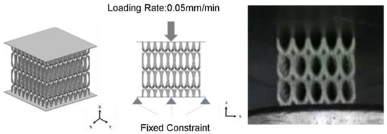
Figure 1.
Schematic diagram of quasi-static compression of the lattice structure.
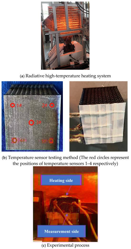
Figure 2.
Thermal insulation performance test of the lattice structure.
2.4. Thermal Insulation Test
The radiation heating system setup is shown in Figure 2a, the sensor attachment method is shown in Figure 2b, and the heating test process is depicted in Figure 2c. The lattice sandwich structure consists of upper and lower panels with a lattice core in the middle. Five temperature sensors, ranging from −200 °C to +1200 °C, were attached to one side of the lattice structure, while the other side was subjected to radiant heating, using high-temperature insulating wool to block radiant heat from heating the other four surfaces. The test temperature was set to 800 °C. Once the temperature of the heated side reached 800 °C, it was maintained, and the temperature changes on the other side were measured. The patch type PT100 temperature sensors are used for measuring temperature.
3. Results and Discussion
3.1. Study on the Compression Properties of the Ti-6Al-4V Diamond Lattice Structure
To ensure a stable compression process of the lattice structure, a suitable form of lattice structure must be chosen. This study selected five types of unit cell structures based on printability—BCC, BCCZ, FCC, FCCZ, and diamond—for quasi-static compression tests, aiming to identify the most stable type of lattice structure during compression with the smoothest stress–strain curve.
The stress–strain curves for different types of lattice structures during actual compression are shown in Figure 3. It can be seen that the BCCZ, BCC, FCC, and FCCZ exhibited noteworthy fluctuations during compression, and the diamond exhibited smaller fluctuations. The fracture elongation of SLM Ti-6Al-4V material was about 17%. When the local deformation reached 17%, the micro-struts of the lattice structure fractured, losing their constraining function, which manifested as fluctuations in the stress–strain curve. As shown in Figure 4a, the stress concentration of various types of lattice cells during compression along the X direction is near the red node, which is also the critical point of failure. The angle between each strut at the red node of BCC, BCCZ, FCC, and FCCZ lattice cells is 90°, while at the red node of diamond lattice structure, the angle between the two struts in the vertical plane (XZ plane) and the two struts in the horizontal plane (YZ plane) is 60°. When compressed along the X direction, the two struts in the horizontal plane of diamond lattice structure will reinforce and strengthen the two struts in the vertical plane. The lattice structure struts will only fracture after significant plastic deformation, and the failure process will be steadier.
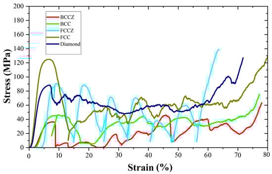
Figure 3.
Compression stress–strain curves of lattice structures.
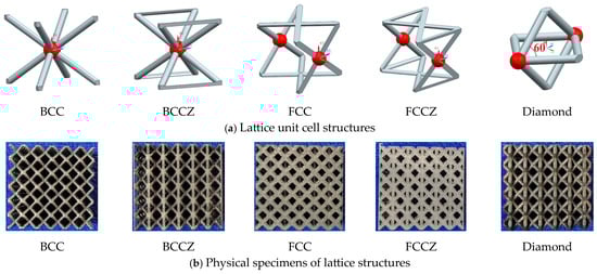
Figure 4.
Various types of lattice structures.
It is evident that, during compression along the X/Y directions, compared to the other four types of lattice structures, the diamond lattice structure exhibited a relatively smoother stress–strain curve, indicating a more stable compression failure process. In order to quantitatively compare the fluctuation of stress–strain curves, Formula (3) was used to solve the stress standard deviation of strains in the 0.1–0.6 (plateau interval). The stress standard deviations of diamond, BCC, BCCZ, FCC, and FCCZ lattice structures were 6.94, 12.62, 13.55, 13.84, and 13.37, respectively. It can be seen that the diamond lattice structure has the smallest standard deviation and the stress plateau segment is smoother. As such, the diamond lattice structure, when used as a filler material in shock absorbers for transportation, provides better protection for spent nuclear fuel. Therefore, this study primarily focuses on the study of compression and thermal insulation performance of the Ti-6Al-4V diamond lattice structure.
where is the stress standard deviation of lattice structure; σ is stress; n is the amount of data.
Ti-6Al-4V diamond lattice structure was designed with a unit cell size of 5 × 5 × 5 mm. The strut diameters, corresponding porosities, and densities of this lattice structure are shown in Table 5. In order to improve the stability of additive manufacturing, while ensuring that the plateau stress of the lattice structure is greater than 5 MPa, the strut diameter of the lattice structure should not be too thin. This paper designs the minimum diameter of the lattice structure to be 0.6 mm for research. The density of the lattice structure is 0.26 g/cm3. The maximum strut diameter of the lattice structure is 1.27 mm, with a density of 1 g/cm3. It can be seen that the density of the lattice structure increases with the increase in strut diameter. By adjusting the strut diameter, the density and load-bearing capacity of the lattice structure can be adjusted.
Table 5.
Parameters of lattice structures with different strut diameters.
Figure 5 shows the portion of the simulation calculation process. As the compression process progresses, the elements near the upper and lower pressure plates of the lattice structure undergo deformation first, and stress concentration occurs near the strut nodes. The local maximum stress reaches 2216.2 MPa as the lattice structure is gradually compacted. Extract the total force and area of the upper and lower pressure plates and calculate the macroscopic stress–strain curve of the lattice structure as shown in Figure 6. It can be observed that during the middle stage of compression, the stress of the lattice structure exhibited a distinct plateau. This is consistent with the typical characteristic of a plateau stress in porous materials with low relative densities. Under external loads, the porous structure underwent localized instability and collapse, forming a deformation zone. This deformation zone gradually expanded to encompass the entire structure under constant stress. This compression characteristic endowed the material with excellent properties such as impact resistance and energy absorption. As the strut diameter of the lattice structure increased, the plateau stress of the diamond lattice structure also increased. When the strut diameter was 0.66 mm, the plateau stress was approximately 7 MPa. When the strut diameter reached 0.9 mm, the plateau stress was approximately 22 MPa. When the strut diameter was 1.12 mm, the plateau stress was approximately 47 MPa. When the strut diameter reached 1.2 mm, the plateau stress was approximately 62 MPa.
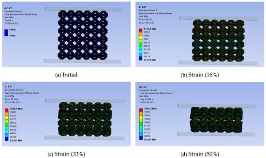
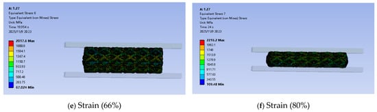
Figure 5.
The portion of the simulation calculation process.
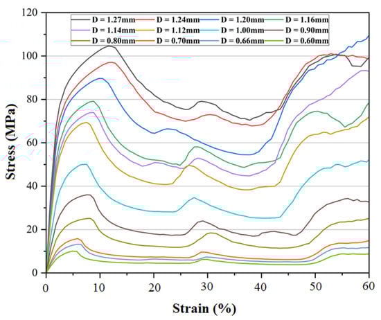
Figure 6.
Stress–strain curves by finite element calculation in the X direction.
The unit cell size is 5 mm × 5 mm × 5 mm, and each sample size is 55 mm × 55 mm × 55 mm. The typical compression process of the diamond lattice structure of TC4 material is shown in Figure 7. As shown in Figure 5, during the compression process, the lattice structure close to the upper and lower plates undergoes plastic deformation and fracture first, followed by plastic deformation and fracture in the middle part of the lattice structure. However, as shown in Figure 7b, during the actual compression process, the random defects inside and on the surface of the lattice structure during additive manufacturing cause local stress concentration, which can lead to premature fracture of the lattice structure in the middle. The struts of the lattice structure do not fracture uniformly, and random fractures may occur due to internal defects and surface states in additive manufacturing, resulting in fluctuations in the stress–strain curve as shown in Figure 8, Figure 9, Figure 10 and Figure 11. The strain is obtained by dividing the true compression by the total height, which is significantly different from the smooth plateau stress exhibited by 316ss lattice structure in reference [16]. The reason for this is that the fracture elongation of TC4 material is relatively small, and it is possible to fracture after small plastic deformation. When compressed, the same layer of struts in the lattice structure do not fracture simultaneously. When a small number of struts fracture, small fluctuations occur, and the stress curve shows a sawtooth shape (as indicated by the black dashed box in Figure 8). When multiple struts fracture simultaneously, the stress curve shows larger fluctuations (as indicated by the green dashed circle in Figure 8).
Figure 7.
Typical compression process in the X-direction of TC4 diamond lattice structure (The area surrounded by the red line is the strut fracture zone).
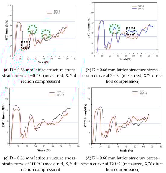
Figure 8.
Stress–strain curves of the D = 0.66 mm lattice structure at different temperatures.
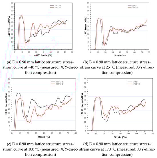
Figure 9.
Stress–strain curves of the D = 0.90 mm lattice structure at different temperatures.
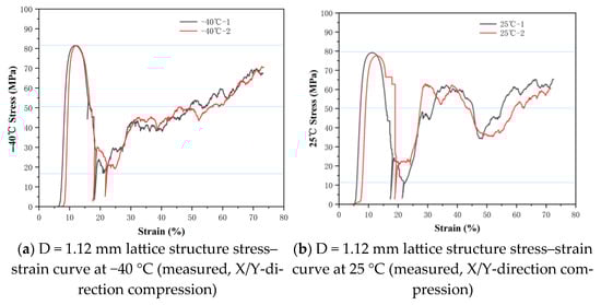
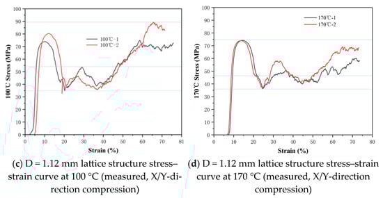
Figure 10.
Stress–strain curves of the D = 1.12 mm lattice structure at different temperatures.
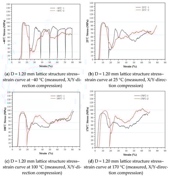
Figure 11.
Stress–strain curves of the D = 1.20 mm lattice structure at different temperatures.
Based on Figure 8, Figure 9, Figure 10 and Figure 11, the correspondence between the measured plateau stress in X/Y directions for different lattice structures is shown (as in Table 6).
Table 6.
Average measured plateau stresses of different lattice structures (X/Y direction).
Table 6 shows that there is little difference in plateau stress for lattice structures with the same strut diameter between −40 °C and 170 °C. The plateau stress at 170 °C is basically the same as that at 25 °C. It can be seen that for Ti-6Al-4V, 170 °C is not sufficient to cause obvious phase transformation or coarsening of precipitates, so its mechanical properties have not changed significantly. Overall, there is little change in the mechanical properties of the lattice structure within the range of −40 °C to 170 °C. This indicates that the TC4 diamond lattice structure maintains good mechanical stability within this temperature range.
As shown in Figure 12, the measured value of the X/Y direction plateau stress closely matched the calculated value, the differences all within 12%, hereby confirmed that the J-C constitutive model and failure model is a suitable tool to design the shock absorber considering its compression properties.
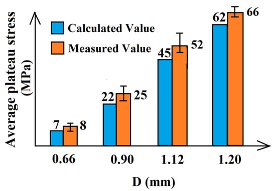
Figure 12.
Comparison chart of finite element simulation calculated values and average measured values of plateau stress.
The lattice structure absorbs energy through the bending, fracture, collapse, and friction of the struts in the compression process. The energy absorbed by the lattice structure can be evaluated by the energy absorbed per unit mass Wm.
where ρ is the density of lattice structure; is strain; is stress.
The mean Wm of lattice structures with different strut diameters is shown in Figure 13. As the deformation increases, the energy absorption of the lattice structure gradually increases. And as the diameter of the lattice structure rod increases, its energy absorption also gradually increases. This is because during the compression process, the lattice structure gradually undergoes elastic deformation, plastic deformation, fracture, and friction, thereby continuously dissipating energy. The larger the rod diameter, the greater the energy consumption due to failure, and the greater the energy absorption per unit mass. Therefore, when weight allows, larger strut diameters should be used as much as possible to increase energy absorption performance.
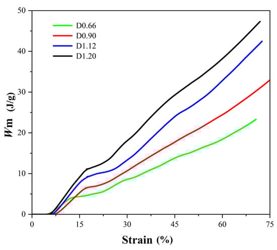
Figure 13.
Mean energy absorbed per unit mass.
3.2. Study on the Thermal Insulation Properties of the Ti-6Al-4V Diamond Lattice Structure
Lattice structures, when used as filler materials for shock absorbers in transportation, not only need to provide shock absorption and impact resistance but should also possess good thermal insulation performance to prevent the internal transfer of external high temperatures, which could harm spent nuclear fuel. In this study, a radiation-based high-temperature heating system was used to heat one side panel of the lattice structure, while temperature sensors were attached to the other side panel to test the thermal insulation performance of the lattice structure. The entire testing process was conducted in an air environment.
Heat transfer in a lattice sandwich structure primarily occurs through three methods: panel heat radiation, strut heat conduction, and core heat convection. As shown in Figure 14, when the heating surface was at 800 °C, the maximum temperatures of the conductive surface of the lattice structure were below 200 °C for strut diameters of 0.66 mm and 0.9 mm; 230 °C for a strut diameter of 1.12 mm; and 250 °C for a strut diameter of 0.20 mm. This suggests that as the density of the lattice structure and plateau stress increased, the maximum temperature of the conductive surface tended to rise, indicating a gradual decrease in thermal insulation performance. Regardless of whether at room temperature or at a high temperature of 800 °C, as the plateau stress of the lattice structure increases, the porosity of the lattice structure (a porous material) decreases, the air gaps reduce, the metallic solid portion increases, and the thermal conductivity increases.
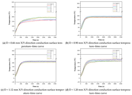
Figure 14.
Thermal insulation performance of lattice structures with different strut diameters (1#, 2#, 3#, and 4# represent the temperatures measured by sensors 1#, 2#, 3#, and 4# in Figure 2b).
4. Conclusions
Considering the compression yield strength, weight, cost, and manufacturability of porous materials, the Ti-6Al-4V lattice structure has potential applications as a filler material for shock absorbers in the transportation of spent nuclear fuel. Actual compression tests on various types of lattice structures have confirmed that the diamond lattice structure has a relatively smoother stress–strain curve, and its compression failure process is more stable, making it a better protective filler material for shock absorbers handling spent nuclear fuel.
The Ti-6Al-4V diamond lattice structure offers excellent energy absorption and thermal insulation performance. With densities below 1 g/cm3, by adjusting the strut diameters, lattice structures with different plateau stresses can be designed to meet the requirements of shock absorbers under different operating conditions. While the plateau stress in the lattice structure increases with density, thermal insulation performance decreases with density. Therefore, when designing filler materials for shock absorbers, it is necessary to balance the plateau stress and thermal insulation performance to achieve the best overall performance.
In the future, the influence of internal and surface defects in additive manufacturing on mechanical properties and stability should be fully considered, and material failure model parameters should be obtained to ensure good consistency between finite element simulation results and actual measurement results throughout the entire dynamic compression process. In order to further promote the application of lattice structure in nuclear spent fuel transportation shock absorbers, the local lattice structure rod diameter size should be optimized based on the strong designability of lattice structure, forming a gradient structure, and achieving the best overall buffering and energy absorption effect by reasonably arranging the direction of lattice structure.
Author Contributions
Conceptualization, W.C. and J.Y.; methodology, W.C. and J.Y.; software, K.L. (Kailun Li); validation, T.Y., X.Z. and Y.Z.; formal analysis, K.L. (Keke Lu); investigation, Z.F.; data curation, W.C., L.C. and J.Y.; writing—original draft preparation, W.C. and J.Y.; writing—review and editing, B.D.; visualization, K.L. (Kailun Li); supervision, B.D.; project administration, J.Y.; funding acquisition, W.C. and J.Y. All authors have read and agreed to the published version of the manuscript.
Funding
This research was funded by Young Talents Program of China National Nuclear Corporation and Self-initiated Project of Institute of Energy, Hefei Comprehensive National Science Center grant number 25KZS406.
Data Availability Statement
The original contributions presented in this study are included in the article. Further inquiries can be directed to the corresponding author.
Conflicts of Interest
Jun Yao, Kailun Li, Xiaofeng Zhang, and Baorui Du declare no conflicts of interest. Wanqi Chen, Tianye Yang, Yue Zheng, Keke Lu, Zhang Fan, and Lan Cui were employed by the China Nuclear Power Engineering Co., Ltd. This study received funding from Young Talents Program of China National Nuclear Corporation and Self-initiated Project of Institute of Energy, Hefei Comprehensive National Science Center grant number 25KZS406. The funder was involved in providing financial support for the research but had no role in study design, data collection and analysis, decision to publish, or preparation of the manuscript.
References
- Da Silva, A.; Kyriakides, S. Compressive Response and Failure of Balsa Wood. Int. J. Solids Struct. 2007, 44, 8685–8717. [Google Scholar] [CrossRef]
- Vural, M.; Ravichandran, G. Dynamic Response and Energy Dissipation Characteristics of Balsa Wood: Experiment and Analysis. Int. J. Solids Struct. 2003, 40, 2147–2170. [Google Scholar] [CrossRef]
- Musolff, A.; Quercetti, T.; Müller, K.; Droste, B.; Gründer, K.-P. Experimental Testing of Impact Limiters for RAM Packages under Drop Test Conditions. Packag. Transp. Storage Secur. Radioact. Mater. 2014, 25, 133–138. [Google Scholar] [CrossRef]
- Diersch, R.; Weiss, M.; Dreier, G. Investigation of the Impact Behaviour of Wooden Impact Limiters. Nucl. Eng. Des. 1994, 150, 341–348. [Google Scholar] [CrossRef]
- Saliba, R.; Mourao, R.P.; Quintana, F.; Novara, O.; da Silva, L.L.; Miranda, C.A.J.; Neto, M.M. Analysis and Design of Spent Fuel Transport Cask Impact Limiters. Packag. Transp. Storage Secur. Radioact. Mater. 2011, 22, 172–178. [Google Scholar] [CrossRef]
- Mane, J.V.; Chandra, S.; Sharma, S.; Ali, H.; Chavan, V.M.; Manjunath, B.S.; Patel, R.J. Mechanical Property Evaluation of Polyurethane Foam under Quasi-Static and Dynamic Strain Rates- An Experimental Study. Procedia Eng. 2017, 173, 726–731. [Google Scholar] [CrossRef]
- Gibson, L.J.; Ashby, M.F.; Schajer, G.S.; Robertson, C.I. The Mechanics of Two-Dimensional Cellular Materials. Proc. R. Soc. London. A Math. Phys. Sci. 1997, 382, 25–42. [Google Scholar] [CrossRef]
- Maji, A.K.; Schreyer, H.L.; Donald, S.; Zuo, Q.; Satpathi, D. Mechanical Properties of Polyurethane-Foam Impact Limiters. J. Eng. Mech. 1995, 121, 528–540. [Google Scholar] [CrossRef]
- Aktay, L.; Johnson, A.F.; Kröplin, B.-H. Numerical Modelling of Honeycomb Core Crush Behaviour. Eng. Fract. Mech. 2008, 75, 2616–2630. [Google Scholar] [CrossRef]
- Yin, H.; Zhang, W.; Zhu, L.; Meng, F.; Liu, J.; Wen, G. Review on Lattice Structures for Energy Absorption Properties. Compos. Struct. 2023, 304, 116397. [Google Scholar] [CrossRef]
- Wu, W.; Xia, R. Design of Lightweight Lattice Meta-Structures and Approaches to Manipulate Their Multi-Functional Mechanical Properties. Adv. Mech. 2022, 52, 673–718. [Google Scholar] [CrossRef]
- Wang, Z.; Lv, Y.; Chen, B.; Zhou, J. Research Progress of Additively Manufactured Energy-Absorbing Structures. Rare Met. Mater. Eng. 2022, 51, 2302–2315. [Google Scholar]
- Wang, T.; An, J.; He, H.; Wen, X.; Xi, X. A Novel 3D Impact Energy Absorption Structure with Negative Poisson’s Ratio and Its Application in Aircraft Crashworthiness. Compos. Struct. 2021, 262, 113663. [Google Scholar] [CrossRef]
- Liang, H.; Sun, B.; Hao, W.; Sun, H.; Pu, Y.; Ma, F. Crashworthiness of Lantern-like Lattice Structures with a Bidirectional Gradient Distribution. Int. J. Mech. Sci. 2022, 236, 107746. [Google Scholar] [CrossRef]
- Shen, Y.; Cantwell, W.; Mines, R.; Li, Y. Low-Velocity Impact Performance of Lattice Structure Core Based Sandwich Panels. J. Compos. Mater. 2014, 48, 3153–3167. [Google Scholar] [CrossRef]
- Yao, J.; Zhao, L.; Ding, R.; Du, B.; Yuan, Y.; Li, K. Study on the Quasistatic Compression Performance of Arch Microstrut Lattice Structure by Selective Laser Melting. Adv. Eng. Mater. 2022, 24, 2101156. [Google Scholar] [CrossRef]
- Yao, J.; Ding, R.; Li, K.; Du, B.; Zhao, L.; Yuan, Y. Study on the Impact Behavior of Arch Micro-Strut (ARCH) Lattice Structure by Selective Laser Melting (SLM). Rapid Prototyp. J. 2022, 28, 1541–1557. [Google Scholar] [CrossRef]
- Nasim, M.; Hasan, M.J.; Galvanetto, U. Impact Behavior of Energy Absorbing Helmet Liners with PA12 Lattice Structures: A Computational Study. Int. J. Mech. Sci. 2022, 233, 107673. [Google Scholar] [CrossRef]
- Yin, S.; Chen, H.; Wu, Y.; Li, Y.; Xu, J. Introducing Composite Lattice Core Sandwich Structure as an Alternative Proposal for Engine Hood. Compos. Struct. 2018, 201, 131–140. [Google Scholar] [CrossRef]
- Deng, H.; Zhao, J.; Wang, C. Bionic Design Method of a Non-Uniform Lattice Structure for a Landing Footpad. Aerospace 2022, 9, 220. [Google Scholar] [CrossRef]
- Park, S.J.; Lee, J.H.; Yang, J.; Moon, S.K.; Son, Y.; Park, J. Enhanced Energy Absorption of Additive-Manufactured Ti-6Al-4V Parts via Hybrid Lattice Structures. Micromachines 2023, 14, 1982. [Google Scholar] [CrossRef] [PubMed]
- Stavropoulos, P.; Foteinopoulos, P. Modelling of additive manufacturing processes: A review and classification. Manuf. Rev. 2018, 5, 2. [Google Scholar] [CrossRef]
- Cao, X.; Duan, S.; Liang, J.; Wen, W.; Fang, D. Mechanical properties of an improved 3D-printed rhombic dodecahedron stainless steel lattice structure of variable cross section. Int. J. Mech. Sci. 2018, 145, 53–63. [Google Scholar] [CrossRef]
- Leary, M.; Mazur, M.; Williams, H.; Yang, E.; Alghamdi, A.; Lozanovski, B.; Zhang, X.; Shidid, D.; Farahbod-Sternahl, L.; Witt, G.; et al. Inconel 625 lattice structures manufactured by selective laser melting (SLM): Mechanical properties, deformation and failure modes. Mater. Des. 2018, 157, 179–199. [Google Scholar] [CrossRef]
- Kaya, G.; Yıldız, F.; Solak, K.; Orhan, S.N. An experimental and FEA investigation of deformation characteristics of additively manufactured Ti6Al4V lattice structures. Eur. J. Mech. A/Solids 2025, 112, 105657. [Google Scholar] [CrossRef]
- Zluhan, B.; Narasimharaju, S.R.; Cholkar, A.; Thomas, K.; Raghavendra, R.; Lopes, E.S. Design, defect analysis, compressive strength and surface texture characterization of Laser Powder Bed Fusion processed Ti6Al4V lattice structures. J. Mater. Res. Technol. 2025, 35, 2914–2933. [Google Scholar] [CrossRef]
Disclaimer/Publisher’s Note: The statements, opinions and data contained in all publications are solely those of the individual author(s) and contributor(s) and not of MDPI and/or the editor(s). MDPI and/or the editor(s) disclaim responsibility for any injury to people or property resulting from any ideas, methods, instructions or products referred to in the content. |
© 2025 by the authors. Licensee MDPI, Basel, Switzerland. This article is an open access article distributed under the terms and conditions of the Creative Commons Attribution (CC BY) license.