Abstract
Multirotor UAVs are becoming increasingly important in both civilian and military fields. In the plateau environment, the endurance time of multirotor UAVs is still too short for mission requirements. Thus, the optimisation of the efficiency of the power system is considered to be an effective way to overcome this problem. This paper presents a practical method of power system design to maximise endurance time in a plateau environment. First, the optimal proportion of battery quality is analysed from the perspective of energy consumption of multirotor UAVs. Second, the modelling method of each component of the power system is studied separately. Then, the endurance solution method is given, the multirotor UAV power system is optimised and analysed according to the given design requirements, and the effectiveness and practicability of the method are verified through experiments.
1. Introduction
In recent decades, the applications of multirotor UAVs have experienced significant growth in both civil and military domains [1,2], which is primarily attributed to their cost-effectiveness and high manoeuvrability. Multirotor UAVs are extensively utilized in various fields, including aerial photography, plant protection, and parcel delivery.
In the extreme environment of the Qinghai-Tibet Plateau, the multirotor UAV has the potential to make a significant contribution to scientific research activities, such as atmospheric monitoring, glacier monitoring, geological exploration, and vegetation phenology surveys. However, harsh environmental conditions, characterised by extremely cold temperatures, low air pressure, and thin air, pose challenges to the performance of multirotor UAVs. These challenges result in reduced payload capacity and endurance time, limiting the effectiveness of UAVs in these specific applications. To overcome these challenges, it is of great research significance to focus on the design and optimisation of multirotor UAV systems specifically tailored for plateau environments. By developing UAV systems optimised for the unique characteristics and demands of plateau environments, it is possible to enhance their performance and capabilities. This research endeavor aims to improve the payload capacity, endurance time, and overall efficiency of multirotor UAVs operating in plateau environments, enabling them to fulfil their potential in scientific research and other applications on the Qinghai-Tibet Plateau.
The power system of a multirotor UAV typically consists of several key components, including a battery pack, propeller, brushless DC motor, and electrical modulation [3]. Some design experiences are introduced in [3], such as a motor with a low KV value (motor velocity constant), should match with a propeller with a large diameter for higher whole efficiency. Among these components, the motor and propeller play a crucial role in determining the overall efficiency of the propulsion system [4,5]. Previous studies have focused on the efficiency analysis [6] and design optimisation [7,8] of propellers. However, it has been emphasised in [3] that the motor and propeller should be considered a unified system since their efficiencies are interdependent. The efficiency of a motor-propeller system is not a fixed value but rather a variable that is influenced by factors such as motor parameters, propeller parameters, and specific flight conditions [9,10,11,12,13,14,15,16,17,18,19,20]. Traditional approaches for determining the characteristics of such dynamic systems have relied on empirical and trial-and-error experiments. However, given the wide range of component products available on the market, this conventional design approach can be costly and time-consuming [21].
The paper is organised as follows. In Section 2, the energy-consumption angle of a multirotor UAV is comprehensively analysed, and the optimal proportion of battery quality is given to maximise the endurance time. Section 3 studies the modelling method of each component of the power system and provides the basic knowledge for the content of Section 4. The solution is given in Section 4 and verified experimentally. In Section 5, the combination of the propeller and motor in the multirotor UAV power system is optimised, and the effectiveness and utility of the method are verified experimentally. Finally, Section 6 presents the conclusion.
2. The Optimal Proportion of Battery Quality
For most electric multirotor UAVs, according to the existing weight statistical model of the rotor UAV, the weight of the power system accounts for more than 70% of the total weight of the UAV, and the weight of the battery accounts for more than 60% of the total weight of the power system. The proportion of UAV energy (battery) will affect the endurance time of the UAV. By introducing the actuator disk model for the power consumption of a propeller in ambient air based on momentum theory, we study the optimal proportion of the battery quality that maximises the endurance of the UAV.
2.1. The Actuator Disk Model for Power Consumption of a Propeller
For an actuator disk model of a propeller that is not translating in the ambient air, the aerodynamic power Paero required may be computed [22] as
where is the thrust produced, is the density of the air, and is the area swept by the rotor. This derivation assumes that the flow is inviscid and incompressible and follows from applying the conservation of mass and energy to a control volume containing the propeller.
The actual power provided from the battery to the power system contains additional losses, which mainly reflect the aerodynamic loss of the propeller (determined by the performance parameters of the propeller) and the loss of the power transmitted to the propeller. We make the simplifying assumption that these losses are all proportional to the power drawn so that the actual power consumption of propeller i producing thrust fi may be captured by
where the constant is a function of the propeller size, ambient air density, propeller figure of merit, and powertrain efficiency. In the dynamic system and environment, it is a constant.
2.2. Battery Quality and Hover Time Analysis
For a symmetrical -rotor UAV with a mass of (including load), the pulling force required for each propeller is , and the total power consumed is:
Set as the energy density of the battery, as the mass of the battery, and as the mass of the UAV without the battery (including the load); then:
where , , and are the masses of a single motor, propeller, and electric modulation, respectively, is the fuselage mass of the multirotor UAV, and is the load mass.
The energy budget provided by the battery to UAV is . The endurance time of UAV is:
where is a constant specific to the aircraft. In the case of , the endurance time of UAV is mainly affected by the battery quality . The derivative of Equation (5) is , and it is set equal to 0 to obtain . At this time, the endurance time of the UAV is the maximum.
3. Modelling of a Multirotor UAV Power System
3.1. Propeller Modelling
For a multirotor, fixed-pitch propellers are often used. Propeller performance depends on thrust T (N) and torque M (N·m). Referring to [23], they are expressed as
where (RPM) is the propeller speed, (m) is the propeller diameter, is the dimensionless pull coefficient, is the dimensionless torque coefficient, and (kg/m3) is the air density of the flight environment.
Based on the leaf element theory, the calculation formulas of and obtained by consulting the relevant literature are as follows [24]:
where , , , , , , and are the blade parameter determined by the shape of the propeller airfoil, is the number of blades, is the pitch, and is the lift gradient.
3.2. Motor Modelling
At present, the electric motor used by the multirotor UAV is a brushless DC motor. The brushless DC motor is a synchronous three-phase permanent-magnet motor that can be modelled as a permanent-magnet DC motor. A common equivalent circuit is shown in Figure 1 below. The motor-equivalent electric power supply voltage (V) and the equivalent electric motor input current (A) are calculated as follows [25]:
where is the nominal no-load KV value of the motor, is the nominal no-load current of the motor, is the internal resistance of the motor in the equivalent circuit, is the nominal internal resistance of the motor on the motor parameter table, is the nominal no-load voltage of the motor, and is the reverse electromotive force constant of the motor.
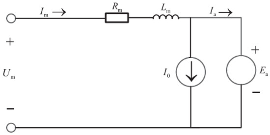
Figure 1.
A common equivalent circuit of a brushless DC motor.
3.3. Electric Modulation Modelling
Electric modulation (also known as ESC) converts the DC voltage in the battery into a three-phase AC signal after duty ratio modulation and input into the brushless motor so that the armature generates an alternating magnetic field and drives the rotor to rotate. The equivalent circuit of electrical modulation is shown in Figure 2, where is the input voltage of electrical modulation, is the input current of electrical modulation, is the equivalent DC voltage after modulation of electrical modulation, is the internal resistance of electrical modulation, and is the maximum voltage that can be supported during normal operation of electrical modulation.
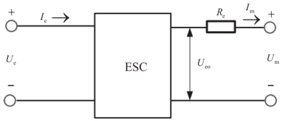
Figure 2.
Electric adjustment equivalent circuit.
It can be obtained from the figure above [25]:
where is the electric throttle command, is the battery voltage, is the battery current, is the battery internal resistance, is the maximum sustained current of electric regulation, is the number of motors (rotors), and is the sum of the current of other airborne equipment.
3.4. Battery Modelling
The battery model mainly uses battery parameters and battery current to solve the multirotor endurance (min). Battery modelling simplifies the actual power-generation process of the battery; that is, it is assumed that the voltage remains unchanged during the discharge process, and the remaining capacity of the battery changes linearly [25].
where is the minimum-remaining capacity of the battery and is the total capacity of the battery (mAh). Generally, the minimum-remaining capacity of a battery is between 15% and 20% of the total battery capacity. The total current of the battery shall not exceed the maximum discharge the current it can bear, which depends on the maximum power-generation ratio of the battery , which shall meet the following requirements [25]:
The battery energy density (Wh/kg) is calculated by the following formula [25]:
4. Expected Endurance
4.1. Endurance Time
It can be seen from the second part that when , the endurance time of the multirotor UAV is the maximum . Therefore, the tension provided by the propeller of the multirotor UAV in hover mode is calculated as follows:
Under the full-throttle command, the tension provided by the propeller is calculated as follows:
where (m/s2) requires the maximum acceleration of the multirotor UAV and is the Earth’s gravitational acceleration.
When the multirotor UAV is hovering, the propeller speed and torque can be obtained by combining formula (6) as follows:
Considering that the nominal no-load current of the motor when the UAV is hovering is far less than the equivalent motor input current, i.e., , let simplify the processing, and the motor voltage and current when hovering can be obtained by combining with Formula (8) as follows:
Considering that when the UAV is hovering at a high altitude, the sum of the current of other airborne equipment is far less than the input current of electric modulation, can be ignored at this time. The battery current can be obtained from Equation (9) as follows:
Combining Formulas (9), (10), (12), (13), (16), and (17) and simplifying throttle instruction in Formula (9) to make , the endurance time of UAV can be obtained as follows:
It is assumed that the endurance index of the designed high-altitude UAV is , and when it is , it indicates that the designed UAV power system has the expected hovering ability. When , the UAV power system does not have the expected hover ability and needs to be optimised.
4.2. Experimental Verification
First, the optimal proportion of battery quality is verified. In Equation (5), let . When is 5 kg, 10 kg, 15 kg, and 20 kg, the relationship curve between (parameters related to battery life) and battery quality is shown in Figure 3 below:
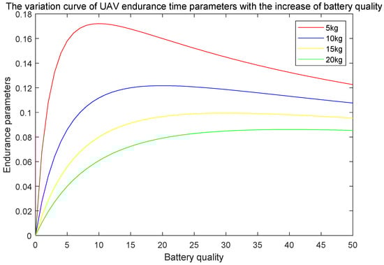
Figure 3.
Related parameters of battery life and battery quality diagram.
As shown in Figure 3, when , is the maximum, and the endurance time of the UAV is the maximum.
The hover performance of the Skylark 3 UAV (as shown in Figure 4) developed by the Shenyang Institute of Automation, Chinese Academy of Sciences, was analysed. The relevant parameters of the power system of the Skylark 3 UAV are as follows:
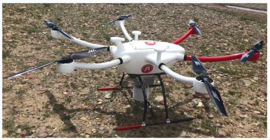
Figure 4.
The Skylark 3 six-rotor UAV was developed by the Institute of Automation of the Chinese Academy of Sciences.
The rotor number was 6, the motor was selected as T-motor U8Lite KV100(T-MOTOR is a brand of China’s Nanchang Sanrui Intelligent Technology Co., Ltd. (Nanchang, China) that focuses on providing safer power systems for multi-rotor UAVs.), the propeller was G28* 9.2CF (i.e., was 28 inches, was 9.2 inches), the electric tuning was FLAME 80A 12S V2.0(T-MOTOR’s electric modulation product model), and the battery was selected as a 12 s lithium battery pack with a total capacity of 50,000 mAh (i.e., was 48 V). The specific parameters of the UAV power system components are shown in Table 1. The drone has a total unloaded mass of 18 kg and can carry a maximum load of 10 kg.

Table 1.
Specific parameters of the Skylark 3 UAV power system components.
In 2020, we conducted a flight performance test of Skylark 3 in Shenyang. In the test, there was no reserved battery allowance (i.e., flight duration measured when battery capacity was exhausted). Then, relevant parameters of the power system of the Skylark 3 UAV were substituted into the above flight duration solution, and the measured and solved phase durations were recorded as shown in Figure 5 below:
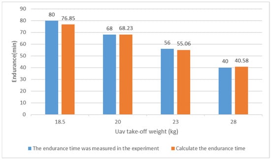
Figure 5.
UAV takeoff weight and endurance.
Figure 5 shows that the endurance calculated by the hovering performance analysis of the rotor UAV is basically consistent with the endurance measured by the experiment, and the error range is within 5%.
On 12 July 2020, we conducted a flight test (dual-light pod) of Skylark 3 on the Guqionggang Glacier (as shown in Figure 6). The altitude of this area is 5.6 km, and the air density is approximately 0.68 kg/m3. This UAV is equipped with a 12 s battery pack with a capacity of 25,000 mAh. The total mass of the UAV is 15.4 kg, and the flight duration of the UAV is 25 min, according to the flight experiment.
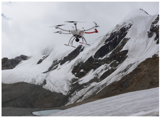
Figure 6.
The on-load endurance test (dual-light pod) of Lark 3 was conducted at Kuqionggang Day Glacier.
Input the relevant parameters of the power system of Yunque 3 UAV into the hovering performance analysis of the multirotor UAV above, and solve the hovering performance parameters in this area when 20% of the battery capacity is reserved as follows:
The endurance obtained by the solution is basically consistent with the experimental endurance, with an error of 8.5%. Considering the wind resistance, frost resistance, and power consumption of the load of the UAV, the error is within the allowable range. The feasibility of this method is verified by two flight tests.
5. The Idea of Optimisation and the Conducted Analysis
5.1. Optimisation of Ideas and Analysis
After consulting the relevant literature and a large number of experiments and analyses, it can be seen that the optimisation of the power system starts from the combination of propeller and motor. Batteries with high energy density and low mass can be selected for energy, and products with low mass and low internal resistance can be selected for electrical regulation [2]. Through existing studies, it is found that the optimisation analysis of the propeller and the optimisation analysis of the motor are mutually coupled, so the model of the motor must be determined first, and the parameters of the propeller can be optimised.
Select a motor and select the maximum propeller suitable for the motor from the motor parameter table. The basic parameters of the propeller are diameter , pitch , and blade number . Known parameters of the propeller airfoil include correction factor , correction factor , correction factor , lift gradient , zero-lift drag coefficient , zero-lift angle of attack , and Oswald factor , brought about by the downwash effect. In the motor-performance parameter table, any throttle command is selected, the propeller generated tension is , the speed is , and the torque is .
The formula for calculating the blade angle and absolute angle of attack of the propeller is as follows:
The dimensionless tension coefficient and torque coefficient of the propeller can be solved by the data in the motor-performance parameter table:
Among them, the standard atmospheric pressure density
The dimensionless tension coefficient and torque coefficient of the propeller are defined as follows [21]:
where is the drag coefficient. The aspect ratio of the propeller can be solved as follows:
The relation between the dimensionless tension coefficient and torque coefficient of the propeller and the absolute angle of attack is as follows [24]:
The parameters of the high-altitude environment of the UAV are altitude , Reynolds number , and air density . When the UAV hovers at an altitude of , the drag coefficient of the propeller is shown as follows:
where is the drag coefficient of the propeller when the UAV is hovering at an altitude of 0 m, which can be measured experimentally. In general, . At this time, the values of propeller torque coefficients and are, respectively, expressed as:
According to the relevant literature, the optimised propeller parameters are expressed as follows [21]:
After optimisation, the propeller tension coefficient and torque coefficient are solved as follows:
When the UAV hovers at an altitude of , the torque coefficient of the propeller is shown as follows:
5.2. Experimental Validation and Analysis
The propeller optimisation analysis of the Skylark 2 UAV (shown in Figure 7) was developed by the Shenyang Institute of Automation, Chinese Academy of Sciences. The relevant parameters of the Llark 2 UAV are as follows:
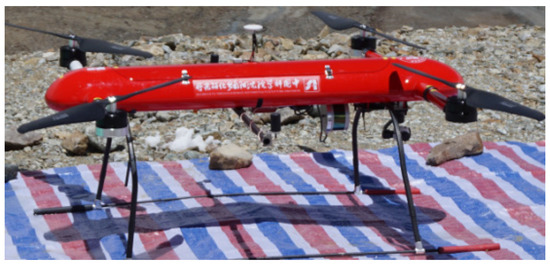
Figure 7.
The Lark 2 quadrotor UAV developed by the Institute of Automation of the Chinese Academy of Sciences.
The rotor number was 4, the motor was selected as T-motor P80 III KV100(T-MOTOR is a brand of China’s Nanchang Sanrui Intelligent Technology Co., Ltd. that focuses on providing safer power systems for multi-rotor UAVs.), the propeller was MF3016 (i.e., was 30.4 inches, was 10.9 inches), the electric tuning was FLAME 80A 12S V2.0(T-MOTOR’s electric modulation product model), and the battery was selected as a 12 s lithium battery pack with a total capacity of 22,000 mAh (i.e., was 48 V). The specific parameters of the UAV power system components are shown in Table 2. The total mass of the UAV is 21.4 kg.
Table 2.
Specific parameters of the Skylark 2 UAV power system components.
According to the relevant parameters of the power system of Yunque 2 UAV and the propeller optimisation analysis above, the propeller optimisation parameters suitable for the 9 km high-altitude environment can be obtained as follows:
According to the optimised propeller parameters, a propeller () was customized by the manufacturer for subsequent testing.
On 9 July 2020, we carried out the flight test of Skylark 2 at the Qinghai-Tibet Plateau Institute of the Chinese Academy of Sciences (as shown in Figure 8). The altitude of the area was 3.64 km, and the air density was approximately 0.85 kg/m3. This UAV was equipped with a 12 s battery pack with 25,000 mAh capacity and carried a 5 kg load. MF3016 OARS and customised OARS were used for testing. At this time, the total mass of the UAV was 21.4 kg and 21.42 kg, respectively, and the endurance time of the UAV was 17 min and 20.3 min, respectively.
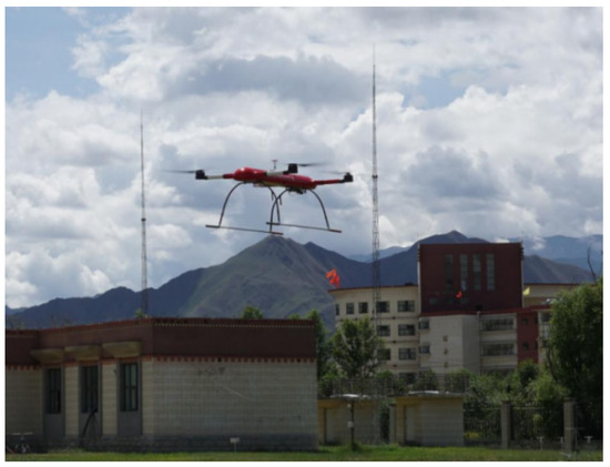
Figure 8.
Flight test of Skylark 2 conducted in Lhasa.
The UAV equipped with the MF3016 paddle and solved optimised propeller () will solve the performance parameters of hovering in this area when the battery reserves 20% capacity, respectively, as follows:
The comparison between the calculated results and those measured in flight experiments is shown in Figure 9.
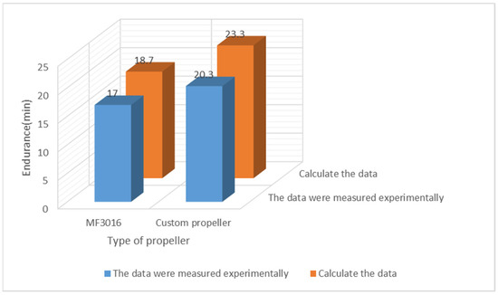
Figure 9.
The results of the computational solution of each propeller and those obtained from the experimental measurement.
Figure 9 shows that for the UAV equipped with MF3016, the error is 10%; the endurance of the UAV equipped with a customized paddle is increased by 19.4% compared with that of the optimised propeller, and the error is 9.8%. Considering the wind resistance, frost resistance, and load consumption, the error is within the allowable range. The feasibility of the proposed optimisation method is verified experimentally.
6. Conclusions
For the application of UAVs in plateau environments, this paper presents a practical method to help designers quickly determine the optimal power system to maximise the durability of multi-rotor UAVs in high-altitude conditions. Firstly, we analyze the optimal proportion of battery mass from the perspective of energy consumption of multirotor UAVs, and its effectiveness is verified by simulation and experiments. Later, this paper establishes the model of the propeller, motor, electric regulation, battery, and other power systems to measure the endurance of UAVs. Based on the theoretical analysis, the key parameters of each part of the power system are estimated, and the parameters of the propeller and motor combination are studied, which is helpful to optimize the efficiency of the UAV power system in the plateau environment and realize a more effective multirotor UAV design. Finally, the effectiveness and utility of this method are verified experimentally. The power system is the most important component of the multirotor UAV, and its design optimisation method will facilitate the rapid optimisation and automatic design of the whole multirotor UAV system or other types of aircraft systems. Theoretical analysis can further directly improve the durability of various UAVs, which is of great significance for future research.
Author Contributions
Conceptualization, T.Q.; methodology, T.Q.; software, T.Q.; validation, T.Q.; formal analysis, T.Q. and G.Z.; investigation, T.Q., G.Z. and Y.H.; resources, L.Y. and Y.H.; data curation, T.Q.; writing—original draft preparation, T.Q; writing—review and editing, T.Q.; visualization, T.Q.; supervision, G.Z.; project administration, L.Y.; funding acquisition, L.Y. and Y.H. All authors have read and agreed to the published version of the manuscript.
Funding
This work was supported in part by the Science and Technology Program of the Tibet Autonomous Region(XZ202101ZD0006G).
Data Availability Statement
Not applicable.
Conflicts of Interest
The authors declare no conflict of interest.
References
- Luo, C.; Yu, L.; Ren, P. A Vision-Aided Approach to Perching a Bioinspired Unmanned Aerial Vehicle. IEEE Trans. Ind. Electron. 2018, 65, 3976–3984. [Google Scholar] [CrossRef]
- Fu, Q.; Quan, Q.; Cai, K.-Y. Robust Pose Estimation for Multirotor UAVs Using Off-Board Monocular Vision. IEEE Trans. Ind. Electron. 2017, 64, 7942–7951. [Google Scholar] [CrossRef]
- Quan, Q. Introduction to Multicopter Design and Control; Springer: Singapore, 2017. [Google Scholar]
- Lawrence, D.; Mohseni, K. Efficiency analysis for long duration electric MAVs. In Proceedings of the Infotech@Aerosp, Arlington, VA, USA, 26–29 September 2005. [Google Scholar]
- Achtelik, M.; Doth, K.-M.; Gurdan, D.; Stumpf, J. Design of a multi rotor MAV with regard to efficiency, dynamics and redundancy. In Proceedings of the AIAA Guidance, Navigation, and Control Conference, Minneapolis, MN, USA, 13–16 August 2012. [Google Scholar]
- Allaka, G.; Anasuya, B.; Yamini, C.; Vaidehi, N.; Ramana, Y.V. Modelling and analysis of multicopter frame and propeller. Int. J. Res. Eng. Technol. 2013, 2, 481–483. [Google Scholar]
- Gamble, D.; Arena, A. Automated dynamic propeller testing at low Reynolds numbers. In Proceedings of the 48th AIAA Aerospace Sciences Meeting Including the New Horizons Forum and Aerospace Exposition, Orlando, FL, USA, 4–7 January 2010. [Google Scholar]
- Kwon, H.-I.; Yi, S.; Choi, S. Design of efficient propellers using variable-fidelity aerodynamic analysis and multilevel optimization. J. Propuls. Power 2015, 31, 1057–1072. [Google Scholar] [CrossRef]
- Ampatis, C.; Papadopoulos, E. Parametric design and optimization of multi-rotor aerial vehicles. In Applications of Mathematics and Informatics in Science and Engineering; Springer: New York, NY, USA, 2014; pp. 1–25. [Google Scholar]
- Moffitt, B.A.; Bradley, T.; Parekh, D.; Mavris, D. Validation of vortex propeller theory for UAV design with uncertainty analysis. In Proceedings of the 46th AIAA Aerospace Sciences Meeting and Exhibit, Reno, NV, USA, 7–10 January 2008. Art. no. 2008-406. [Google Scholar]
- Merchant, M.P.; Miller, L.S. Propeller performance measurement for low Reynolds number UAV applications. In Proceedings of the 44th AIAA Aerospace Sciences Meeting and Exhibit, Reno, NV, USA, 9–12 January 2006. Art. no. 1127:2006. [Google Scholar]
- Torenbeek, E.; Wittenberg, H. Flight Physics: Essentials of Aeronautical Disciplines and Technology, with Historical Notes; Springer: Dordrecht, The Netherlands, 2009. [Google Scholar]
- Liu, P.-Q. Air Propeller Theory and Its Application; Beihang Univ. Press: Beijing, China, 2006. (In Chinese) [Google Scholar]
- Jun, C.; Yang, S.-X.; Li, M. Modeling and experimental analysis of UAV electric propulsion system. J. Aerosp. Power 2009, 24, 1339–1344. (In Chinese) [Google Scholar]
- Lundström, D.; Amadori, K.; Krus, P. Automation of design and prototyping of micro aerial vehicle. In Proceedings of the 47th AIAA aerospace sciences meeting including the new horizons forum and aerospace exposition, Orlando, FL, USA, 5–8 January 2009. [Google Scholar] [CrossRef]
- Lindahl, P.; Moog, E.; Shaw, S.R. Simulation, design, and validation of an UAVSOFC propulsion system. IEEE Trans. Aerosp. Electron. Syst. 2012, 48, 2582–2593. [Google Scholar] [CrossRef]
- Yao, J.; Jiao, Z.; Ma, D.; Yan, L. High-accuracy tracking control of hydraulic rotary actuators with modeling uncertainties. IEEE/ASME Trans. Mechatron. 2014, 19, 633–641. [Google Scholar] [CrossRef]
- Magnussen, Ø.; Ottestad, M.; Hovland, G. Multicopter design optimization and validation. Model. Identif. Control 2015, 36, 67–79. [Google Scholar] [CrossRef]
- Magnussen, Ø.; Hovland, G.; Ottestad, M. Multicopter UAV design optimization. In Proceedings of the 2014 IEEE/ASME 10th International Conference on Mechatronic and Embedded Systems and Applications (MESA), Senigallia, Italy, 10–12 September 2014; pp. 1–6. [Google Scholar]
- Lundstr, D.; Amadori, K.; Krus, P. Automation of design and prototyping of micro aerial vehicle. In Proceedings of the Automation of Design and Prototyping of Micro Aerial Vehicle, Orlando, FL, USA, 5–8 January 2009. Art. no.2009–629. [Google Scholar]
- Dai, X.; Quan, Q.; Ren, J.; Cai, K.-Y. Efficiency Optimization and Component Selection for Propulsion Systems of Electric Multicopters. IEEE Trans. Ind. Electron. 2019, 66, 7800–7809. [Google Scholar] [CrossRef]
- Jain, K.P.; Tang, J.; Sreenath, K.; Mueller, M.W. Staging energy sources to extend flight time of a multirotor UAV. In Proceedings of the 2020 IEEE/RSJ International Conference on Intelligent Robots and Systems (IROS), Las Vegas, NV, USA, 25–29 October 2020. [Google Scholar]
- Deters, R. Performance and Slipstream Characteristics of Small-Scale Propellers at Low Reynolds Numbers. Ph.D. Dissertation, Aerospace Engineering in the Graduate College, University of Illinois at Urbana-Champaign, Champaign, IL, USA, 2014. [Google Scholar]
- Dai, X.; Quan, Q.; Ren, J.; Cai, K.-Y. An Analytical Design-Optimization Method for Electric Propulsion Systems of Multicopter UAVs with Desired Hovering Endurance. IEEE/ASME Trans. Mechatron. 2019, 24, 228–239. [Google Scholar] [CrossRef]
- Shi, D.; Dai, X.; Zhang, X.; Quan, Q. A Practical Performance Evaluation Method for Electric Multicopters. IEEE/ASME Trans. Mechatron. 2017, 22, 1337–1348. [Google Scholar] [CrossRef]
Disclaimer/Publisher’s Note: The statements, opinions and data contained in all publications are solely those of the individual author(s) and contributor(s) and not of MDPI and/or the editor(s). MDPI and/or the editor(s) disclaim responsibility for any injury to people or property resulting from any ideas, methods, instructions or products referred to in the content. |
© 2023 by the authors. Licensee MDPI, Basel, Switzerland. This article is an open access article distributed under the terms and conditions of the Creative Commons Attribution (CC BY) license (https://creativecommons.org/licenses/by/4.0/).