Abstract
In recent years, solar energy has been used as an energy source for many different applications. Currently in the area of Unmanned Aerial Vehicles (UAVs), there are research studies that incorporate this renewable energy technology to increase the vehicle’s autonomy. This technique also needs particular construction techniques and electronic boards, designed to reduce weight and increase the efficiency of all solar systems on board the UAV. As is well known, the amount of generated solar energy could be increased throughout a day a sun tracking technique is added. The present paper proves that the roll angle of a fixed wing UAV can be used to track the sun to increase the energy generated by the solar panels placed on the wing. In that case, the plane’s attitude must be compensated with the yaw angle control to be able to perform a photogrammetric mission. This will be achieved using a control strategy based on the super-twisting technique that ensures convergence in finite time even in the presence of bounded perturbations. The design of the control laws as well as the numerical simulation and real flight results are shown to validate the use of the sun tracking system.
1. Introduction
The use of renewable energy has had a significant impact on many applications. Some of the most used renewable energies are wind and solar energy [1]. The latter energy source has advanced remarkably, particularly with solar cells which are made of various materials, making them smaller and lighter. Some of these solar cells are capable of providing an efficiency of 23% [2] or even 33.7% [3] in current works.
The above-mentioned technological advances, together with new construction techniques, have allowed the incorporation of these technologies into fixed wing UAVs (Unmanned Aerial Vehicles). It has been shown that combining solar energy with a traditional Lithium battery increases the autonomy of the vehicles [4]. A common use for this technology can be found in homes or solar parks, capable of energizing a single home or an entire city, respectively [5]. Some of these solar panels used a sun tracking technique, so that the solar zenith angle is kept equal to zero [6], to increase the amount energy production during a day. A comparison between a fixed-angle photovoltaic (PV) panel and a PV panel with simple solar tracking system is shown in Figure 1.
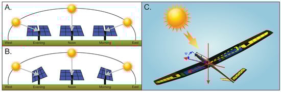
Figure 1.
(A) Position of a fixed photovoltaic panel over a day. (B) Position of a simple solar tracker system over a day. (C) Attitude position of the glider tracking the sun.
Solar Energy in UAV
For a correct implementation of the solar system in a UAV, it is necessary to identify some central parameters, important for the operation and performance of the system. It is important to know that the solar radiation depends mainly on the latitude as demonstrated in Reference [7]. Therefore, the place of operation of the vehicle will determine the payload capacity of the UAV and the necessary amount of solar cells to perform a flight.
One of the main factors in the production of solar energy is the geometrical relationship between solar radiation and the UAV, as shown in References [8,9]. When the incidence angle of the solar radiation is perpendicular to the surface of the solar panel, it will generate the maximum power and it will decrease as the angle is smaller or larger than 90 as explained in References [10,11], where solar tracking techniques were used in order to increase the produced energy. A simple solar tracker system is proposed to increase the autonomy of a UAV. Figure 2 shows the UAV attitudes required for photogrammetry missions.
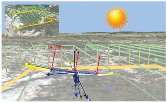
Figure 2.
Geometrical relationship between the sun and SUAV during sun tracking.
Another important factor to consider is the total efficiency of the systems. Indeed, the conversion of solar energy to electrical power implies a long chain involving solar cells, the conversion circuit, the Maximum Power Point Tracker (MPPT) control, the Electronic Speed Control (ESC) and motor and propeller efficiencies. The largest loss in that chain occurs in the solar panels. However in 2030, advances in technology could reach solar cells with an efficiency of , as well as improvements in the types of batteries for energy storage [12].
Considering the above, the main contribution of the present paper is to prove that the solar tracking technique operates properly in fixed-wing UAVs and can generate more energy than that required to perform the necessary attitude. Therefore, the main contributions of the article are as follows:
(1) A control strategy will be proposed for the yaw angle of the UAV including a solar tracking technique. The yaw angle controller will be used to track a desired path using a super-twisting control technique achieving maximum energy generation. The improvement with respect to the controller in Reference [13] is that a roll angle different from zero will not induce a turn of the yaw angle. A reference of the pursuit attitude can be seen in Figure 1 and Figure 2.
(2) The Super-Twisting control technique will be used, since it has already been experimentally tested in a quadrotor aircraft. This technique ensures convergence in finite time to a desired position under bounded perturbations, such as wind disturbances [14]. This technique has also been tested in numerical simulations for fixed wing prototypes [13].
Fixed wing aircraft have been controlled using different techniques like backstepping [15], sliding mode [15], robust nonlinear control [16], neuronal network [17] and even super-twisting controls [18]. A comparison between non-linear controllers based on backstepping, sliding mode and nested saturations, were done in Reference [19] showing that sliding mode control has good performance in yaw and roll movements. The sliding mode control strategy uses less energy consumption than the others but suffers from high frequency chattering. In order to reduce such phenomenon and retain the benefits of a control based on sliding modes, a Super-Twisting control technique was proposed.
(3) The present paper also demonstrates the correct operation of the Super-Twisting control technique when applied to fixed wing vehicles using the aerodynamic parameters obtained by the XFLR5 software in the numerical simulation of the complete lateral dynamic and in real-time experiments. The performed tests showed that the solar tracking technique increased the autonomy of the UAV, that is, the energy generated is larger than the energy used to perform the maneuver.
The present work is organized as follows: Section 2 depicts the mathematical model used for the control of the Solar Unmanned Aerial Vehicle (SUAV), following the design of the control technique for the roll and yaw angle; Section 3 shows the numerical simulations performed to validate the proposed control. This section also presents the real time experiment and energy production results; finally, Section 4, presents the conclusion and future research directions.
2. Materials and Methods
2.1. Airplane Mathematical Model
The SUAV shown in Figure 3 will be used as a reference frame to apply the Super-Twisting algorithm, it is important to mention that the UAV is a sailplane aircraft, modified to use solar energy. Nonetheless, the maximum amount of solar cells that could be incorporated into the aircraft, produced enough solar energy for the operation of the propulsion system to maintain a straight and level flight but could not be employed to recharge the LiPo battery or energize any other aircraft’s system.
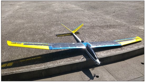
Figure 3.
SUAV used as a references frame.
The SUAV model proposed in this article is a fixed wing UAV with a V-Tail configuration—some specifications are shown in Table 1. This aircraft is equipped with a thrust control and 4 control surfaces, two ailerons and two ruddervators, the latter pair of surfaces are proper for a V-tail.

Table 1.
System specification of the Solar Unmanned Aerial Vehicle (SUAV) prototype.
The thrust () controls the amount of rpm of the brushless motor, the ailerons () controls the torque of roll and the ruddervators expressed by & for left and right ruddervator respectively, whose differential movement has the same effect as a rudder represented by and driving the ruddervators together has the same effect as an elevator represented by .
Mathematically, it is possible to represent the ruddervators as a typical rudder-elevator configuration, through the Equation (1). Therefore the mathematical model for forces and torque of a V-tail aircraft can be expressed in terms of standard (rudder-elevator) notation [20].
The aircraft motion is referenced to an inertial frame, since only normal atmospheric flight is considered, denoting its motion and rotation in terms of a fixed body coordinated system, whose origin is at the center of gravity of the SUAV, as shown in Figure 4, summarizing the variables in Table 2. Defining the attitude of the aircraft as the angular difference between the body-fixed axes and the earth axes (inertial frame).
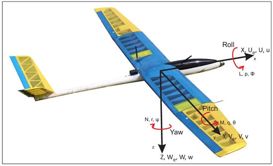
Figure 4.
Coordinated system of the SUAV.
Table 2.
Summary of variables.
To obtain the dynamic model, the Newton-Euler approach was applied through Equations (2) and (3), which were developed and expressed in terms of the movement variables defined in Table 2.
where F is the total force, m the mass, a represents the inertial acceleration, M is the moment, I denotes the moment of inertia and symbolizes the angular acceleration. The total force of the components (X, Y, Z) acting on the body is given by the sum of the force increment over the whole body. This is expressed for the x-axis in the following equation. The same procedure is performed on the other axes.
Consider the inertial force components in the RHS (Right Hand Side) of Equation (3) that create a moment component about each of the three body axes. The following equation is obtained for the x-axis where L is the total moment over that axis. The same procedure can be used for M and N.
Taking into account Equations (4) and (5) and developing the forces and moments over the three axes, the generalized six degrees of freedom equations of motion of a rigid symmetric airframe having uniform mass distribution, are described in Equation (6). The RHS of Equation (6) describes the disturbing and perturbation forces and moments, due to aerodynamic (a) and gravitational (g) effects, movement of aerodynamic control (c), power (p) effects and atmospheric disturbances (d) effects.
The SUAV will fly in a stable undisturbed atmosphere and in steady trimmed straight flight, so it will have small perturbations over angular and linear velocities. Solving each of the terms expressed, simplifying the equation in lateral and longitudinal motion and expressing it in the state space form, the lateral motion is described as follows:
where the elements of the state matrix are the aerodynamic stability derivatives, referred to airplane body axes and the input matrix are the control derivatives. The full dynamical model can be found in Reference [21].
2.2. Super-Twisting Solar Tracker Control Design
The design of the controls laws based on the Super-Twisting control algorithm are presented throughout this section. The objective is that the SUAV could track the sun using the roll angle control [13] and follows a given direction using the yaw angle control.
2.2.1. Roll Angle Controller
Knowing that the perturbation is small and the roll movement involves almost pure rolling motion with little coupling with respect to sideslip or yaw, a reduced order model of the lateral-directional dynamics retaining only the roll mode is expressed as follows:
To further simplify the analysis, we will assume that the aircraft is in wind axes, so we can assume that
Assuming that the main control of the roll angle is obtained using the ailerons, the rudder will be neglected and assuming some external disturbance we get
where is a realistic perturbation that can affect the flight performance in particular the achievement of the desired roll angle. To ensure the desired roll angle of the SUAV in presence of external perturbations, we can obtain the following differential equation set
Defining the following errors
and proposing the following control law
with
where is the super-twisting component of the roll control with coefficients chosen by the following expressions
where W is the sum of disturbances that affect the aerial vehicle dynamics. We can see that the control law in Equation (15) will drive the vehicle to the desired angle in finite time, if and only if the conditions gains and are satisfied. Therefore, it can be concluded that
This condition ensures a stable performance of the SUAV when it tracks the sun over the roll angle. A complete description of the development of the control can be found in Reference [13].
2.2.2. Yaw Angle Controller
Due to the small angle established for the roll angle, the aircraft tends to turn over the yaw angle. Therefore, it is necessary to perform a control for this last angle with two objectives, to counteract the effect of the roll angle and perform the desired paths.
A similar procedure used to control the roll angle will be used for the yaw angle. Considering the lateral dynamics given by Equation (7), as previously used the disturbances are small and knowing that the roll angle is limited and controlled by Equation (15), then a reduced order model of the lateral-directional dynamics could be expressed as follows
Considering the dynamics described above, we will implement a non-linear controller design based on Super-Twisting control in order to reach accurately the desired yaw angle. From the above we can assume that
Assuming that the main control of the yaw angle is obtained using the rudder and neglecting the ailerons we get
Considering that
where is the effect of the yaw angle on the slip over the y-axis and the turn on the z-axis, we obtain
We will assume as external disturbance the effect of , along with the external disturbances that can affect flight performance, especially in a trajectory tracking.
To avoid losing the system stability due to disturbances we require the following conditions:
for some constants . Therefore, a robust control algorithm is proposed motivated by the super-twisting control to ensure the desired yaw angle of the SUAV in presence of external perturbations. So we have the following differential equation set
Then we define the errors as
The desired yaw angle will be achieved if we design a state feedback control law to ensure that for are bounded and converge to zero at a finite time, ensuring boundedness of the angle given that the desired position is bounded. Then, we start with the simple system
where is viewed as a control input, we can stabilize the origin using the linear control
so that
where the design parameter is chosen such that the reconstruction error dynamic dominant characteristic equation is Hurwitz, having the form
Designing the sliding manifold represented by “s” as follows
and
Therefore, if the control law enforces the desired angle in the phase space such that in (33), then the error converges in finite time since
Proposing the following control law
with
where is the Super-Twisting component of the yaw control with coefficients chosen as the one of the roll control. Let us choose and rewrite the last equation in the form:
According to inequalities given by Equation (25) and considering the new variable the last equation can be rewritten as
Assuming that the perturbations terms of the system Equation (40) are bounded by
for some constants . Then the origin is an equilibrium point that is stable if the gains of the controller Equation (38) satisfy
Using the control strategy proposed in Equation (37) the yaw angle will converge to the desired yaw angle in a finite time, if and only if the conditions on the gains and are satisfied, which will be obtained by the wind measurements obtained from the pitot tube, implying that in finite time. Therefore, it can be concluded that
This condition ensures a stable performance of the tracking of the defined paths of the SUAV, the stability proof of the perturbed system Equation (40) can be seen in Appendix A. Simulation results for the active solar tracking using the controller proposed are presented below.
3. Results
3.1. Simulations
This section presents the simulation results of system Equation (7) using the Super-Twisting controller that ensures the tracking of the sun with the roll angle to reach maximum solar energy over a day and the ability to control the direction of the SUAV when the proposed yaw angle controller is on and off, even when the roll angle is different from zero.
To demonstrate the importance of the yaw control for the solar tracking technique, a first simulation without the yaw controller and the controller proposed in Reference [13], with a desired roll angle of 2 and 6 degrees, was performed to demonstrate the effect of the latter angle over the angle. The results from the simulation are shown in Figure 5.
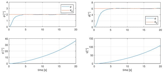
Figure 5.
Effects of angle due to sun tracking technique over angle.
As it is known, the angles of the lateral dynamics are coupled, so a movement in roll modifies the angle and it is then necessary a yaw control to be able to modify the direction of the SUAV.
In order to perform more realistic simulations, a wind profile from previous flights with a maximum wind gust of 26 m/s was used in all the simulations, to disturb the angular dynamics of roll and yaw and not the position of the aircraft, this profile can be seen in Figure 6. It is important to mention that the initial condition for the roll angle is different from zero in the simulations so that the stability of the control is preserved. Notice that in the real time tests, the control would start acting when the SUAV leaves a turn.
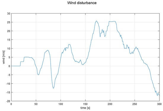
Figure 6.
Wind profile used as perturbation for all the simulation.
To illustrate the effects of the perturbation over the angle, a simulation without the effects of the angle is shown in Figure 7, where it can be seen that the yaw angle varies up to about 30 degrees, which implies that it is not possible to control the direction.
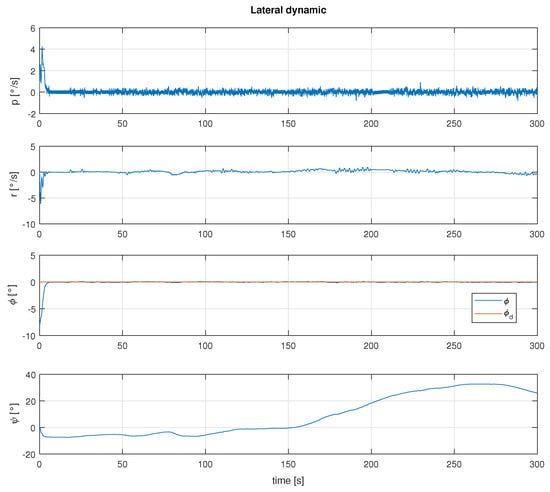
Figure 7.
Behavior of the phi angle due to the wind disturbance.
This motivates the controller proposed in the present paper. A simulation with both yaw and roll controller can be seen in Figure 8, where a desired angle of and of 2 and 0 degrees, respectively, were set to test the stability and convergence of the proposed controllers, working simultaneously.
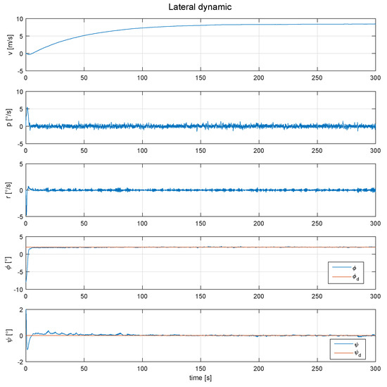
Figure 8.
Behavior of the lateral dynamic of the SUAV, with the roll and yaw angles controlled.
As can be seen in Figure 8, the roll and yaw angle are controlled and follow the desired position, however the variable “v”, which denotes the linear velocity on the y-axis, increases in a way that a direction control would be impossible. Tthe position of the controls are shown in Figure 9.
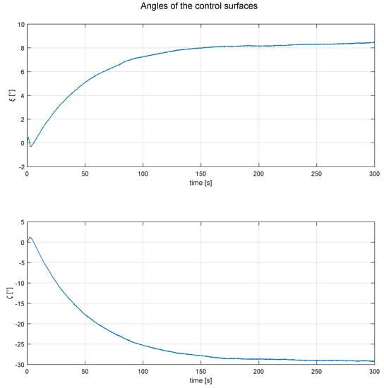
Figure 9.
Behavior of control surfaces, for the simulation showed in Figure 8.
A final simulation was performed to demonstrate the proposed controllers’ ability to counteract the effect caused by the roll angle and the perturbation introduced, as it can be seen in Figure 10, where a desired and angle of 2 and −12 degrees was respectively fixed. In the same figure it is shown that it is possible to follow a trajectory, with the control used for the yaw angle.
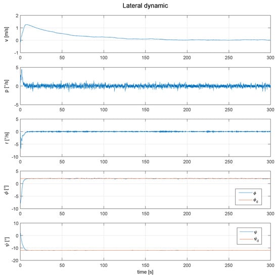
Figure 10.
Behavior of the lateral dynamic of the SUAV, with the roll and yaw angle fixed, in order to extend the autonomy and follow a desired path.
The angles of deflection of the control surfaces used for the last simulation are shown in the Figure 11, where a smoother behavior of the control surfaces movement can be seen in Figure 9. Finally, we can appreciate that the controllers proposed for the SUAV are useful and can reach the desired roll and yaw angles, nevertheless, to perform trajectories used for photogrammetry as shown in Figure 2, it is important to develop or integrate a tracking trajectory control as in References [22,23,24].
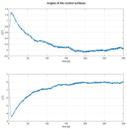
Figure 11.
Behaviour of aileron () and rudder (), for the simulation showed in Figure 10.
3.2. Real Time
In this section we present the results obtained from a real flight with the SUAV showed in Figure 12, with both proposed controllers active to control a fixed roll and yaw angle, in order to implement the sun tracking technique without losing the stability of the SUAV. To measure the attitude (), an on board IMU of the Emlid Navio 2 with a Raspberry Pi 3 model B+ was used.
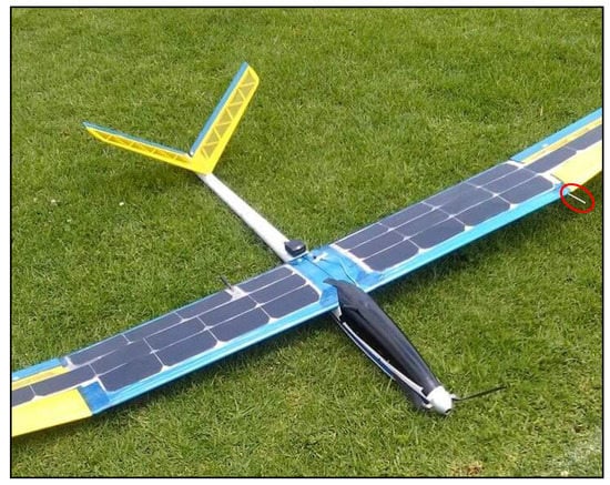
Figure 12.
SUAV in the flight field, doing a pre-flight check. Pitot-tube is marked in red.
As can be seen in Figure 13, the flight field established for the experimental tests in the laboratory is marked in green, in yellow a field that belongs to another institution in which the flights can be made with caution, and in red, all areas with houses and buildings where experimental tests are not allowed for safety reasons. Due to the reduced space of the flight field (230 m) and the cruising speed of the plane (23 m/s), the time for the flight test was 12 s maximum. Even more of the initial conditions were different from zero, since the glider was leaving a turn to the left to start in the space where the control tests were performed, as already mentioned. To measure the wind disturbances, a pitot tube was used, which is indicated in Figure 12.
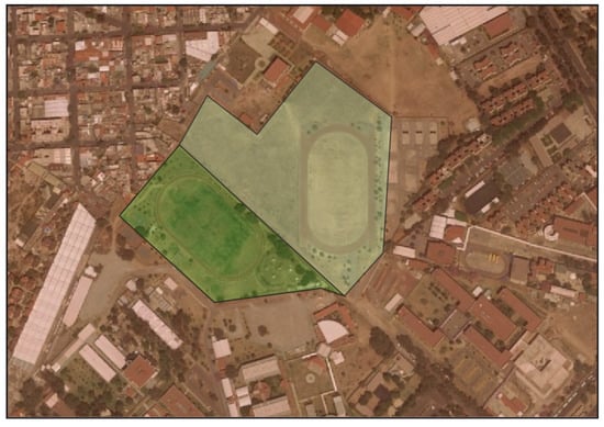
Figure 13.
Flight field restrictions.
Two flight tests were performed with a fixed roll angle at 2 and 6 degrees respectively, to check the performance of the controls and the glider (there were wind gusts of 8 m/s when the experiment was carried out), as well as power generation. Figure 14 shows the performance of the Super-Twisting controls over the and angles under real flight conditions, setting 2 and 110 degrees for the phi and psi angles, respectively.
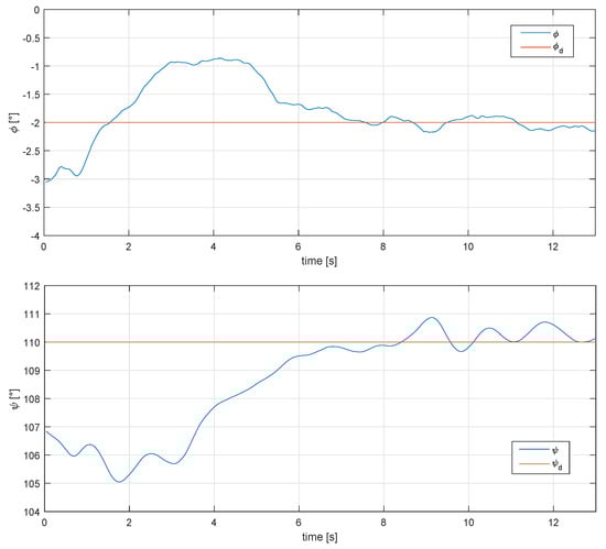
Figure 14.
Behavior of the phi and psi angle under real conditions, for a 2 degree roll angle and 110 degree psi angle.
The phi angle was selected to follow a straight line when the control over the roll angle was used. For a better appreciation of the results, a representation of the airplane’s attitude is shown in Figure 15 and Figure 16, using real flight data.
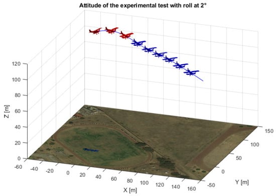
Figure 15.
3D view of the airplane’s attitude for a 2 degree roll angle.
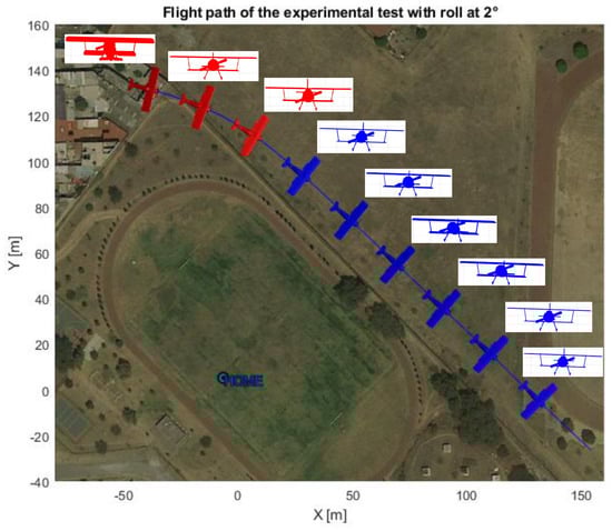
Figure 16.
Top and front view of the airplane’s attitude for a 2 degree roll angle.
The red and blue colors indicate when the autopilot and proposed controls are being used, respectively. A second test was carried out to confirm that the proposed yaw could compensate for the effects of high values of roll angle. The results are shown in Figure 17.
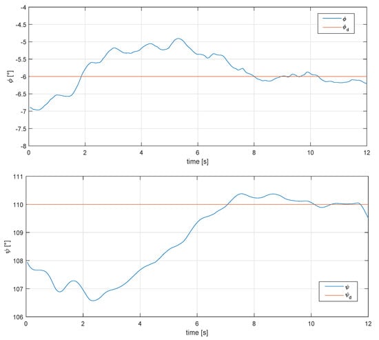
Figure 17.
Behaviour of the phi and psi angle under real conditions, for a 6 degree roll angle and 110 degree psi angle.
A representation of the airplane’s attitude is shown in Figure 18 and Figure 19, using real flight data.
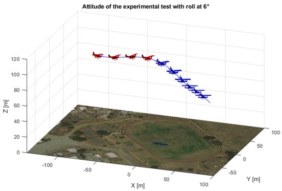
Figure 18.
3D view of the airplane’s attitude for a 6 degree roll angle.
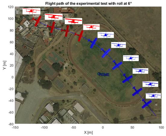
Figure 19.
Top and front view of the airplane’s attitude for a 6 degree roll angle.
3.3. Energy Production
To asses the usefulness of the solar tracking technique applied to a fixed wing UAV, a comparative graph in Figure 20 of the solar radiation over the solar panel depending on the roll angle, was obtained through a conversion of lux to watts, which was measured by a lux sensor.
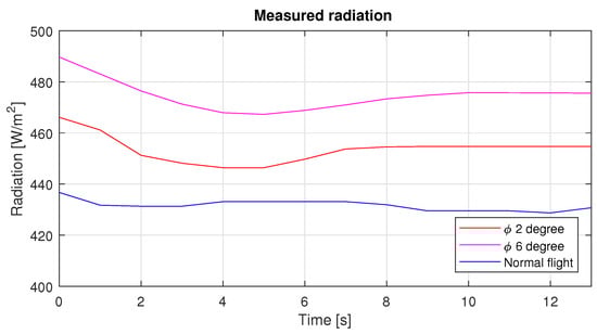
Figure 20.
Radiation over the solar cells during the three different roll angle.
As can be seen in Figure 20, the radiation over the plane in a straight and level flight was 430 W/m on average, while when the roll angle was set at 2 and 6 degrees this had an increase of 24 and 45 W/m, respectively. The photovoltaic system has an overall efficiency of 7 percent, so the power produced by this system can be seen in Figure 21.
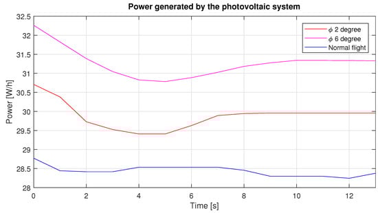
Figure 21.
Power generated by the photovoltaic system during the three different roll angles.
Through the movement of roll it is possible to generate a greater amount of energy, as can be seen in Figure 21; however, as mentioned in the introduction, it is necessary to know the position of the sun. This can be calculated through equations using the local longitude, day and time as shown in Reference [25]—with this information we can set a roll angle.
To validate the use of the solar tracking technique for a SUAV, it is necessary to show that the energy produced is larger than the energy consumed. With Figure 22 and Figure 23, we can show that the servos power consumption increases when maintaining a constant roll angle. Nevertheless, the consumption does not increase much for small roll angles, as is the case for large roll angles and sharp turns like those before and after the performed experiments shown with blue dotted lines in Figure 24 and Figure 25.
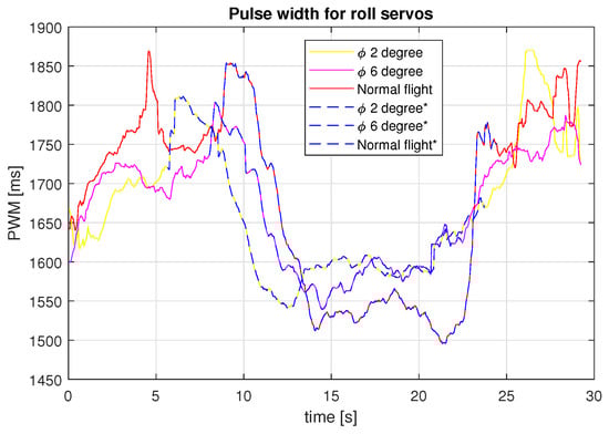
Figure 22.
PWM signal over the roll servos for the different tests carried out.
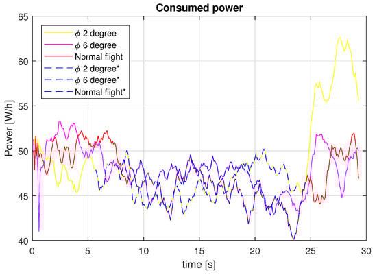
Figure 23.
Consumed power for the different tests carried out.
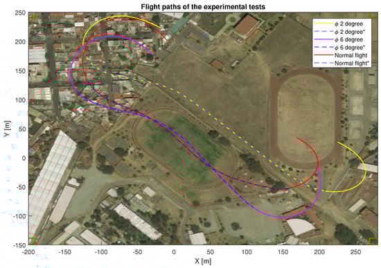
Figure 24.
Flight paths for the different tests carried out.
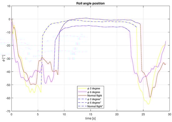
Figure 25.
Roll angle for the different tests carried out.
4. Discussion and Conclusions
Standard airplane design includes flight stability specifications under normal conditions. Notice, however, that in the present paper the plane may be required to fly at a roll angle different from zero in order to increase the energy produced by the solar panels.
Based on the robustness properties of the Super-Twisting control algorithm, we were able to present an SUAV for tracking the sun in order to produce as much energy as possible from the solar radiation without altering the stability of the aircraft. The airplane roll angle required to maximize the produced energy was computed on board. For stability reasons, the desired roll angle was kept in the interval ().
The airplane’s capability to track a predefined direction was tested in numerical simulations as well as in real experiments. The experimental results showed that the aircraft was able to follow the desired path with the yaw control and still maintain the set roll angle constant despite wind perturbations.
Compared with other controllers, such as those presented in the introduction, the Super Twisting control technique provided the robustness needed to reach the desired reference even in the presence of external disturbances, reducing the chattering phenomenon of the sliding mode.
It is important to point out that the maximum roll angle has been computed to ensure that the solar zenith angle is zero for a limited period of time, for which it is still possible to control the direction to track a flight path. Furthermore, during that period the produced energy is greater than the energy lost due to drag.
In the real time tests that were carried out, an increase of 12 percent extra energy was achieved, representing around 3.5 watts of energy, while the extra energy consumed to perform the maneuver was less than that generated, as can be seen in Table 3. However, the increase in energy could be larger by appropriately establishing the roll angle and performing flight patterns from north to south.
During the experimental test, the SUAV suffered an incident with the brushless motor. Indeed, the maximum take-off weight of the glider was surpassed which led to a motor break down. In future work, we will use a new UAV with better performance, including a trajectory control.
In addition to the new prototype, three tests will be developed performing a simulation of a photogrammetric mission, the first using only the battery to power the SUAV, the second using the combined battery-solar power system and the last with the solar tracking technique active, to check the different autonomies for each case.
As can be seen in Figure 23, the power consumption increases as the roll angle is larger due to the servomechanism consuming energy for moving the aileron to a desired angle. In order to accurately measure the power consumed by the actuators, it would be necessary to include a current sensor.
So a flight field will be searched for, where longer flight paths can be developed to better test the proposed control. Finally, this research demonstrated that it is possible to develop a solar tracking technique with a fixed wing SUAV for generating additional solar energy and the Super-Twisting controls developed with the aerodynamic parameters for the entire lateral dynamic had good performance.
Author Contributions
Conceptualization, J.L.H.-T. and I.G.-H.; Methodology, J.L.H.T., I.G.-H. and R.L.; Software, J.L.H.-T. and I.G.-H.; Validation, J.L.H.-T., I.G.-H. and R.L.; Formal analysis, J.L.H.-T. and R.L.; Investigation, J.L.H.-T.; Resources, I.G.-H. and R.L.; Data curation, I.G.-H. and R.L.; writing–original draft preparation, J.L.H.-T.; writing–review and editing, I.G.-H. and R.L.; Visualization, J.L.H.-T.; Supervision, I.G.-H.; Project administration, R.L.
Funding
This research received no external funding.
Conflicts of Interest
The authors declare no conflict of interest.
Appendix A. Stability Analysis
To prove stability of the equilibrium of the perturbed system Equation (39) in finite time, we propose the following Lyapunov candidate function [26]
The proposed Lyapunov candidate function can be written as a quadratic form
where and the matrix P is defined as
Therefore, is negative definite if . It is easy to see that this is the case if the gains are chosen as in (42). Now consider the following inequalities
replacing
where
is the Euclidean norm of . After that, using inequality (A9) we have that the equation (A6) is rewritten as
or else
by using (A10) and the fact that in (A11) we obtain that
with defined as
From Equation (A14) one obtains that V converges to zero in finite time at most after
We can see that the control law in Equation (16) will drive the vehicle to the desired angle in a finite time, if and only if the conditions on the gains and are satisfied implying that . Therefore, it can be concluded that
This condition ensures a stable performance of the SUAV when it will track a path with the yaw angle.
References
- Zeng, F.; Bie, Z.; Li, X.; Han, Z.; Zhi, Y.; Zhang, Y. Annual renewable energy planning platform: Methodology and design. In Proceedings of the 13th IEEE Conference on Automation Science and Engineering (CASE), Xi’an, China, 20–23 August 2017; pp. 1392–1397. [Google Scholar] [CrossRef]
- Green, M.A.; Emery, K.; Hishikawa, Y.; Warta, W. Solar cell efficiency tables (version 37). Prog. Photovolt. Res. Appl. 2011, 19, 84–92. [Google Scholar] [CrossRef]
- Elshorbagy, M.H.; García-Cámara, B.; López-Fraguas, E.; Vergaz, R. Efficient Light Management in a Monolithic Tandem Perovskite/Silicon Solar Cell by Using a Hybrid Metasurface. Nanomaterials 2019, 9, 791. [Google Scholar] [CrossRef] [PubMed]
- Noth, A. Design of Solar Powered Airplanes for Continous Flight. Ph.D. Thesis, ETH Zurich, Zurich, Switzerland, 2008. [Google Scholar]
- Rehman, A.U.; Shah, S.M.A.; Shah, S.A.R.; Badshah, S.; Khattak, M.A. Prospects of rural electrification of Balochistan province with renewable energy sources. In Proceedings of the 3rd International Conference on Power Generation Systems and Renewable Energy Technologies (PGSRET), Johor Bahru, Malaysia, 4–6 April 2017; pp. 95–100. [Google Scholar] [CrossRef]
- Leluţiu, L.M.; Lungoci, C.M.; Călin, M.D.; Cirstea, M. A power efficient mobile solar tracking system. In Proceedings of the International Conference on Optimization of Electrical and Electronic Equipment (OPTIM) & 2017 Intl Aegean Conference on Electrical Machines and Power Electronics (ACEMP), Brasov, Romania, 25–27 May 2017; pp. 561–566. [Google Scholar]
- Rajendran, P.; Smith, H. Implications of longitude and latitude on the size of solar-powered UAV. Energy Convers. Manag. 2015, 98, 107–114. [Google Scholar] [CrossRef]
- Nadia, A.R.; Isa, N.A.M.; Desa, M.K.M. Advances in solar photovoltaic tracking systems: A review. Renew. Sustain. Energy Rev. 2017, 82, 2548–2569. [Google Scholar]
- Wu, J.; Wang, H.; Li, N.; Yao, P.; Huang, Y.; Su, Z.; Yu, Y. Distributed trajectory optimization for multiple solar-powered UAVs target tracking in urban environment by Adaptive Grasshopper Optimization Algorithm. Aerosp. Sci. Technol. 2017, 70, 497–510. [Google Scholar] [CrossRef]
- Zsiborács, H.; Bai, A.; Popp, J.; Gabnai, Z.; Pályi, B.; Farkas, I.; Baranyai, N.; Veszelka, M.; Zentkó, L.; Pintér, G. Change of real and simulated energy production of certain photovoltaic technologies in relation to orientation, tilt angle and dual-axis sun-tracking. A case study in Hungary. Sustainability 2018, 10, 1394. [Google Scholar] [CrossRef]
- Asiabanpour, B.; Almusaied, Z.; Aslan, S.; Mitchell, M.; Leake, E.; Lee, H.; Fuentes, J.; Rainosek, K.; Hawkes, N.; Bland, A. Fixed versus sun tracking solar panels: An economic analysis. Clean Technol. Environ. Policy 2017, 19, 1195–1203. [Google Scholar] [CrossRef]
- Abbe, G.; Smith, H. Technological development trends in Solar-powered Aircraft Systems. Renew. Sustain. Energy Rev. 2016, 60, 770–783. [Google Scholar] [CrossRef]
- Hernandez, J.L.; González-Hernández, I.; Lozano, R. Super-twisting control in a Solar Unmanned Aerial Vehicle: Application to Solar Tracking. In Proceedings of the International Conference on Unmanned Aircraft Systems (ICUAS), Dallas, TX, USA, 12–15 June 2018; pp. 379–384. [Google Scholar] [CrossRef]
- González-Hernández, I.; Salazar, S.; Muñoz, F.; Lozano, R. Super-twisting control scheme for a miniature Quadrotor aircraft: Application to trajectory-tracking problem. In Proceedings of the International Conference on Unmanned Aircraft Systems (ICUAS), Miami, FL, USA, 13–16 June 2017; pp. 1547–1554. [Google Scholar]
- Espinoza, T.; Dzul, A.; Lozano, R.; Parada, P. Backstepping-sliding mode controllers applied to a fixed-wing UAV. J. Intell. Robot. Syst. 2014, 73, 67–79. [Google Scholar] [CrossRef]
- Callegati, F.; Naldi, R.; Melega, M.; Marconi, L. Robust nonlinear control of miniature fixed-wing UAVs. In Proceedings of the European Control Conference (ECC), Aalborg, Denmark, 29 June–1 July 2016; pp. 2584–2589. [Google Scholar]
- Bhandari, S.; Raheja, A.; Tang, D.; Ortega, K.; Dadian, O.; Bettadapura, A. Nonlinear control of UAVs using multi-layer perceptrons with off-line and on-line learning. In Proceedings of the American Control Conference (ACC), Portland, OR, USA, 4–6 June 2014; pp. 2875–2880. [Google Scholar]
- Castaneda, H.; Salas-Pena, O.S.; de León Morales, J. Adaptive super twisting flight control-observer for a fixed wing UAV. In Proceedings of the International Conference on Unmanned Aircraft Systems (ICUAS), Atlanta, GA, USA, 28–31 May 2013; pp. 1004–1013. [Google Scholar]
- Espinoza, T.; Dzul, A.; García, L.; Parada, R. Nonlinear Controllers Applied to Fixed-Wing UAV. In Proceedings of the IEEE Ninth Electronics, Robotics and Automotive Mechanics Conference, Cuernavaca, Mexico, 19–23 November 2012; pp. 243–248. [Google Scholar] [CrossRef]
- Beard, R.; McLain, T. Navigation, Guidance, and Control of Small and Miniature Air Vehicles; Brigham Young University: Provo, UT, USA, 2010; pp. 40–41. [Google Scholar]
- Cook, M.V. Flight Dynamics Principles: A Linear Systems Approach to Aircraft Stability and Control; Butterworth-Heinemann: Oxford, UK, 2012. [Google Scholar]
- Zhang, M.; Su, C.; Liu, Y.; Hu, M.; Zhu, Y. Unmanned aerial vehicle route planning in the presence of a threat environment based on a virtual globe platform. ISPRS Int. J. Geo-Inform. 2016, 5, 184. [Google Scholar] [CrossRef]
- Wu, J.; Wang, H.; Su, Z.; Shao, X. UAV Broken-Line Path Following under Disturbance Conditions. J. Aerosp. Eng. 2018, 31, 04018089. [Google Scholar] [CrossRef]
- Rucco, A.; Aguiar, A.P.; Pereira, F.L.; de Sousa, J.B. A predictive path-following approach for fixed-wing unmanned aerial vehicles in presence of wind disturbances. In Robot 2015: Second Iberian Robotics Conference; Springer: Lisbon, Portugal, 2015; pp. 623–634. [Google Scholar]
- Kona, P.S.; Iyengar, P.V.; Conrad, J.M. Algorithm-based, single axis rotation of a solar panel apparatus for low power devices. In Proceedings of the SoutheastCon 2015, Fort Lauderdale, FL, USA, 9–12 April 2015; pp. 1–5. [Google Scholar] [CrossRef]
- Moreno, J.A.; Osorio, M. A Lyapunov approach to second-order sliding mode controllers and observers. In Proceedings of the 47th IEEE Conference on Decision and Control (CDC), Cancun, Mexico, 9–11 December 2008; pp. 2856–2861. [Google Scholar]
© 2019 by the authors. Licensee MDPI, Basel, Switzerland. This article is an open access article distributed under the terms and conditions of the Creative Commons Attribution (CC BY) license (http://creativecommons.org/licenses/by/4.0/).