Abstract
So-called “Type IX” chute spillways with impact baffle blocks have been used successfully around the globe for over 50 years. A key advantage of the chute spillway is the elimination of a costly stilling basin allowing for a more simplistic outlet works design. The current design process is based upon physical models developed in the 1950s and observation of completed projects over the last 50 years. The design procedure is empirical and provides the designer with a range of workable layouts, baffle heights, and baffle spacing. Unfortunately, this approach may not be optimal. This first study of a longer research effort focus uses Monte Carlo simulations and computational fluid dynamics (CFD) to examine the design methodology and physical model basis for the current design procedure. Initially, the study examined the design procedure with a Monte Carlo simulation to explore the range of acceptable designs that can be realized. Then, using CFD, full-scale prototype (located in Gila, Arizona USA) physical model results that were a key basis for the current design procedure were recreated. The study revealed that a wide range of acceptable chute designs can result from following the current design procedure but that some of these may be better than others. The study also outlines future research efforts needed to revise the current design methodology.
PACS:
J0101
1. Introduction
This article explores the current design of Bureau of Reclamation Type IX chute spillways using Monte Carlo simulations and computational fluid dynamics (CFD) modeling. Type IX chute spillways [1] with impact baffle blocks have been used around world for many years. In these spillway designs, the baffles act as impact dissipators that use the associated energy dissipation to render flows to acceptable velocities. A key advantage of chute spillways with baffles is the elimination of a costly downstream stilling basin allowing for a more simplistic outlet works design. However, the current design procedure, as recommended by the Bureau of Reclamation [2,3], relies upon empirical relationships for sizing the spillway width, spillway slope, side walls, and impact baffles. The resulting design can fall within a fairly large range. This initial study first used stochastic evaluations developed from Monte Carlo simulations to assess the reasonable range of spillway and baffle designs that may be realized by following the existing design procedures. Then the study explored the performance of an existing baffled spillway that was used in the original Bureau of Reclamation physical model testing that served as the primary basis for the current design procedures. The actual prototype baffled spillway, located in Gila, Arizona USA [4], was simulated using three-dimensional CFD modeling. Figure 1 shows an existing baffled chute in Montana documented as an example for this paper with photo taken by the first author.
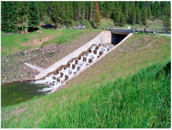
Figure 1.
Example baffled chute spillway in Bozeman, Montana USA (photo from C. Brown).
Surprisingly, limited research work has been conducted on baffled chute spillways since the 1970s. Most current research on spillway performance and design has been directed toward experimental hydraulic studies [5,6], model simulations [7,8,9,10], or ecological impact assessments [11,12,13]. Much of the current research focus is on the design of efficient and safe stepped spillways [7]. Therefore, this study is unique and extremely useful with its focus upon improving the overall standard chute spillway design procedure. A chute spillway includes the spillway itself, training side walls that keep flows contained within the spillway, and baffles that reduce flow velocity. This paper will focus on those design issues that are primarily a function of the baffle height and spillway width. Figure 2 shows a general schematic half-section, along with recommended design dimensions, for a baffled chute spillway [2,3].
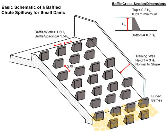
Figure 2.
Example baffled chute spillway half-width schematic with design guidelines included.
2. Materials and Methods
2.1. Monte Carlo Simulations
This initial study was completed in two parts. First, a stochastic study was completed on the Gila, Arizona, USA, prototype spillway to explore the range of baffle designs that can be realized by following the current design procedures. The stochastic study used the Monte Carlo simulation tool Yasai [14] which is an add-in program to Microsoft ExcelTM. The Monte Carlo simulation assumed that the design spillway inflow had a coefficient of variation (COV) of 15%, the difference in water head across the spillway had a COV of 15%, and all other dimensions and variables had COVs of 1.5%. Based upon the design procedure recommended by the Bureau of Reclamation [2,3], two different, yet plausible, design spillway layouts were developed called the “minimalist” and the “conservative” designs, respectively. The minimalist design started with a baffle height of 80% of the critical depth in typical rectangular channel as specified by the Bureau of Reclamation as the minimum allowable [2]. The conservative design started with a baffle height of 90% of the critical depth of a typical rectangular channel as specified by the Bureau of Reclamation as the upper limit for baffle dimensions [2]. Both the minimalist design and the conservative design were then modified to include the full parameter uncertainty using the stochastic tools in Yasai instead of just a simple deterministic calculation. The simulation results for the Monte Carlo simulation were segregated into the 10 and 90 percentiles from which the two spillway layouts were developed.
2.2. Computational Fluid Dynamic (CFD) Modeling
The second part of the study included CFD modeling of the original Gila, Arizona, USA, prototype spillway for the purposes of reproducing the original physical model testing results gathered in the field experiments. This effort, a proof-of-concept simulation, was developed so that confidence in the CFD technique could be gained permitting other, future simulations to evaluate alternate spillway and baffle layouts including both the minimalist and conservative designs mentioned above.
The CFD model utilized Siemens’ Star-CCM+ [15] with k-epsilon Reynolds-averaged Navier–Stokes (RANS) turbulence closure. The mass and mass momentum transport equations associated with this model are:
with k, the turbulent kinetic energy; V, the cell volume; vg, the grid velocity; a, the face-area vector; μ, the dynamic viscosity of the fluid; μt, the turbulent viscosity; σk and σε, turbulent Schmidt numbers; ε, the turbulent dissipation rate; ε0, the ambient turbulence value in the source terms that counteracts turbulence decay; ΓM, the dilation dissipation coefficient; ν, the kinematic viscosity of the fluid; and Sk and Sε are user-specified source terms. Details about evaluating the turbulence terms are found in a number of references [16]. The models’ computational domain consisted of long (approximately 40 m) culvert that emptied into an area with the baffled dam described by [2] as shown on Figure 3. The flow domain was extended upward by 15.24 m (50 ft) to allow space for air.
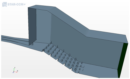
Figure 3.
Modeled geometry in Star-CCM+ (not shown is a wall toward the reader which would close the model).
Two fluid phases were modeled throughout all computations—air and water. The ideal gas law was used to describe air while water was assumed to be incompressible and have a density of 998 kg/m3. Wall boundary conditions were assumed at all boundaries except for the model’s upstream inlet (i.e., mouth of culverts) and downstream outlet. The culvert mouths were models as “Velocity Inlets” whereby velocity vectors were specified perpendicular to the culvert mouth faces. The model’s outlet was a “Flow-Split Outlet” whereby all fluid flowing through the model was given a path out of the model.
Results were computed using several meshes and implicit time steps. While a full-blown Richardson extrapolation was not conducted, the research team is confident in the preliminary results since data were reproduced with relative accuracy (please see below). Ultimately, the mesh configuration consisted of hexagonal cells with an approximate base size of 0.35 m. A refinement region everywhere water was expected to flow—i.e., within the culverts, along the dam face, and near the outlet. Cells in this region contained a base size of 0.1125 m. This resulted in approximately 3.85 million cells. The final implicit time step was 5 ms.
Initial model conditions were such where the computational domain was filled with air. Then, water was introduced to the model via the culverts’ velocity inlets at a volumetric flow rate of about 35.4 cubic meters per second (cms). The model was allowed to run for 45-s of real-time. During the Gila, AZ experiments, piezometric pressure was measured along various baffles. Monitors were set up to monitor pressures at these locations within the computational model and these data were compared with experimental results. In addition, after the models were run, the center-line water surface profile was plotted and compared with approximate centerline profile from the AZ experiment.
3. Results
3.1. Monte Carlo Simulations
The Monte Carlo simulation included 10,000 iterations to explore the full range of possible design dimensions for the spillway, baffles, and chute spillway training side walls. The baffle height dimension varied within a range of 0.68 m to 2.23 m when reviewing the 1% and 99% rank from the Monte Carlo simulation. For this study, the 10% and 90% ranks were used to develop the two comparable designs. The baffle height for the 10% mimalist design was determined to be 0.77 m while the 90% maximum conservative design yielded an estimate of 1.13 m. The minimum chute side training wall height ranged from 2.41 m for the 10% minimalist design to 3.26 m for the conservative design. The minimalist design includes 10 rows of baffles with 45 total full or partial baffles. The conservative design includes 9 rows of larger baffles with 32 total full or partial baffles. The conservative design would require about 57% more concrete to construct fewer baffles in quantity but much larger baffles in terms of size. Therefore, the overall cost of the conservative design would be 57% higher than the minimalist design for the baffle line item. Table 1 summarizes the Monte Carlo simulation results.

Table 1.
Monte Carlo simulation results for the minimalist and conservative designs.
3.2. CFD Model Results
During the experiments described in [2], mean upstream baffle pressure on Baffles A, B, and D (first 4 rows of baffles) was 1.68 m of water. However, on Baffle C, mean upstream pressure was only 0.40 m of water. These pressures are consistently lower than pressures on the other three baffles and may indicate that there was an issue with the data. Modeled resutls were compared with experimental data both including and excluding data from Baffle C (Figure 4). As shown, when Baffle C was excluded, the data match was relatively close. However, a moderate amount of scatter between measured and modeled data was also observed. In addition, the observed water surface was slightly higher than the simulated water surface from the comptuational model—particularly as one moves further downstream (Figure 5). One of the model runs is available as a video animation in Video S1 in Supplementary Materials.
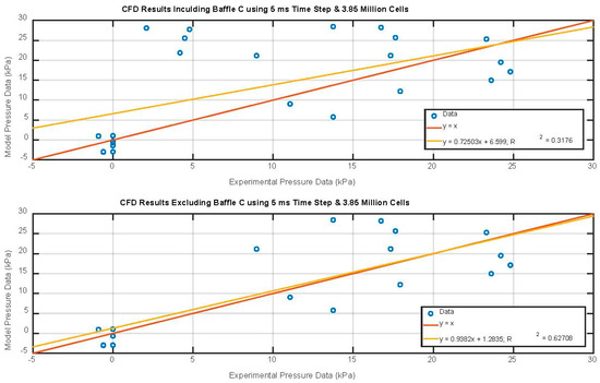
Figure 4.
Comparison between modeled and measured pressures.
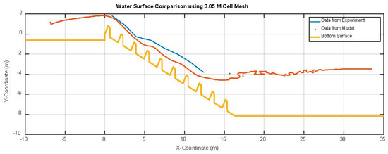
Figure 5.
Modeled and measured water surfaces.
4. Discussion
Overall, this study has provided the beginnings of a focused research effort regarding the design of baffled chute spillways. The results of the Monte Carlo simulations clearly demonstrate that the current design procedure can produce completely different, albeit, acceptable designs. This study used the current procedure to develop two different designs to be used in future research, namely the so-called minimalist design and the conservative design. The conservative design resulted in much larger baffles that required about 57% more concrete than the minimalist design. Then, using a CFD model, the study replicated physical model studies of a prototype baffled chute spillway originally tested in the 1950s. The purpose of this research exercise was to try to reproduce the original field data with the CFD model in order to provide a “proof-of-concept” methodology for the purposes of ultimately refining the chute spillway design procedures. Future research is planned to further refine the model of the prototype since the calibration and validation effort is not entirely complete. Then, the research team intends to use the CFD tool to create two additional models (e.g., minimalist design and conservative design) as variations to the prototype in order to refine the current design procedure with the goal of developing a more cost-effective approach.
5. Conclusions
In summary, this initial research study of Type IX baffled chute spillways demonstrated that the current design procedure is very subjective which can lead to varying spillway designs which are more expensive than required. Further studies are necessary to refine the current design procedure. The research team proposes to complete further CFD modeling of the hypothetical “minimalist” spillway design and the “conservative” spillway design. The results of these two simulations will then be compared to the original prototype spillway design to determine which of the two designs might be more efficient, thus leading to refinements in the current design procedure.
Supplementary Materials
The following are available online at www.mdpi.com/xxx/s1, Video S1.
Author Contributions
C.B. led the research efforts for this article as part of his research program. The conceptualization of the work was performed by C.B. The Monte Carlo simulations were prepared and run by C.B. The CFD model development was undertaken by R.C. with review by C.B. The formal analysis was completed by C.B. and R.C. This article was written by C.B. and R.C. C.B. provided project administration and final article editing.
Funding
This research was unfunded and completed by Brown and Crowley as a follow up study related to dam spillways.
Acknowledgments
The authors would like to acknowledge previous United States Bureau of Reclamation physical model tests on chute spillways as the basis for this study.
Conflicts of Interest
The authors declare no conflict of interest. No one other than the authors had a role in the design of the study; in the collection, analyses, or interpretation of data; in the writing of the manuscript; or in the decision to publish the results.
References
- Tullis, B.P.; Bradshaw, R.D. Impact dissipators. In Energy Dissipation in Hydraulic Structures, 1st ed.; Chanson, H., Ed.; CRC Press: Boca Raton, FL, USA, 2015; Chapter 6. [Google Scholar]
- United States Bureau of Reclamation. Design of Small Dams, A Water Resources Technical Publication, 3rd ed.; United States Bureau of Reclamation: Denver, CO, USA, 1987; pp. 358–362. [Google Scholar]
- Peterka, A.J. Hydraulic Design of Stilling Basins and Energy Dissipators, Engineering Monograph 25, A Water Resources Technical Publication, 8th ed.; United States Bureau of Reclamation: Denver, CO, USA, 1984; pp. 153–189. [Google Scholar]
- United States Bureau of Reclamation. Hydraulic Model Studies of the Outlet Control Structure, Culvert under Dike, and Wash Overchute at Station 938+00, Wellton-Mohawk Division, Gila Project, Arizona, Laboratory Report # Hyd-359; United States Bureau of Reclamation: Denver, CO, USA, 1953; pp. 9–25. [Google Scholar]
- Gonzalez, C.A.; Chanson, H. Hydraulic design of stepped spillways and downstream energy dissipators for embankment dams. Dam. Eng. 2007, 22, 223–244. [Google Scholar]
- Abdelhaleem, F.F. Effect of semi-circular baffle blocks on local scour downstream clear-overfall weirs. Ain Shams Eng. J. 2013, 4, 675–684. [Google Scholar] [CrossRef]
- Tabbara, M.; Chatila, J.; Awwad, R. Computational simulation of flow over stepped spillways. Comput. Struct. 2005, 83, 2215–2224. [Google Scholar] [CrossRef]
- Kirkgoz, M.S.; Akoz, M.S.; Oner, A.A. Numerical modeling of flow over a chute spillway. J. Hydraul. Res. 2009, 47, 790–797. [Google Scholar] [CrossRef]
- Valero, D.; Bung, D.; Crookston, B.; Matos, J. Numerical Investigation of USBR Type III Stilling Basin Performance Downstream of Smooth and Stepped Spillways. In Proceedings of the 6th IAHR International Symposium on Hydraulic Structures, Portland, OR, USA, 27–30 June 2016; pp. 652–663, ISBN 978-1-884575-75-4. [Google Scholar] [CrossRef]
- Li, S.; Zhang, J.; Xu, W. Numerical investigation of air-water flow properties over steep flat and pooled stepped spillways. J. Hydraul. Res./J. Rech. Hydraul. 2018, 56, 1. [Google Scholar] [CrossRef]
- Bylak, A.; Kukuła, K.; Plesiński, K.; Radecki-Pawlik, A. Research Paper: Effect of a baffled chute on stream habitat conditions and biological communities. Ecol. Eng. 2017, 106 Pt A, 263–272. [Google Scholar] [CrossRef]
- Towler, B.; Mulligan, K.; Haro, A. Derivation and application of the energy dissipation factor in the design of fishways. Ecol. Eng. 2015, 83, 208–217. [Google Scholar] [CrossRef]
- Kaya, N.; Emiroglu, M.E. Study of oxygen transfer efficiency at baffled chutes. In Proceedings of the Institution of Civil Engineers-Water Management; Thomas Telford Ltd.: London, UK, 2010; Volume 163, p. 447. [Google Scholar] [CrossRef]
- Eckstein, J.; Riedmueller, S.T. YASAI: Yet Another Add-in for Teaching Elementary Monte Carlo Simulation in Excel. INFORMS Trans. Educ. 2002, 2, 12–26. [Google Scholar] [CrossRef]
- Siemens. User Gude Star-CCM+ Version 12.02; Siemens Aktiengesellschaft: Munich, Germany, 2018. [Google Scholar]
- Crowley, R.; Robeck, C.; Dompe, P. A three-dimensional computational analysis of bridges subjected to monochromatic wave attack. J. Fluids Struct. 2018, 79, 76–93. [Google Scholar] [CrossRef]


© 2018 by the authors. Licensee MDPI, Basel, Switzerland. This article is an open access article distributed under the terms and conditions of the Creative Commons Attribution (CC BY) license (https://creativecommons.org/licenses/by/4.0/).