Abstract
A novel self-contained, electro-hydraulic cylinder drive capable of passive load-holding, four-quadrant operations, and energy recovery was presented recently and implemented successfully. This solution greatly improved energy efficiency and motion control in comparison to the state-of-the-art, valve-controlled systems typically used in mobile and offshore applications. The passive load-holding function was realized by two pilot-operated check valves placed on the cylinder ports, where their pilot pressure was selected by a dedicated on/off electrovalve. These valves can maintain the actuator position without consuming energy, as demonstrated on a single-boom crane. However, a reduced drop of about 1 mm was observed in the actuator position when the load-holding valves were disengaged to enable the piston motion using closed-loop position control. Such a sudden variation in the piston position that was triggered by switching the load-holding valves could increase up to 4 mm when open-loop position control was chosen. For these reasons, this research paper proposes an improved control strategy for disengaging the passive load-holding functionality smoothly (i.e., by removing this unwanted drop of the piston). A two-step pressure control strategy is used to build up pressure before disengaging the pilot-operated check valves. The proposed experimental validation of this method eliminates the piston position’s drop highlighted before and improves motion control when operating the crane in open-loop position control. These outcomes benefit those systems where the kinematics amplify the piston motion significantly (e.g., in aerial platforms) increasing, therefore, operational safety.
1. Introduction
Hydraulic cylinders are commonplace in many fields of industry due to their high-force capability. Valve-controlled systems normally drive these actuators using multiple architectures [1]. The ongoing interest in energy savings and plug-and-play installation is making valveless, self-contained solutions an alternative technology. Removing the fluid throttling in control valves improves the energy efficiency greatly [2,3,4,5,6,7,8]. Proposing self-sufficient, electro-hydraulic assemblies with a sealed reservoir, arranged in closed-circuit configuration, and with a wired connection to the electric grid facilitates the commissioning enormously. Solutions with a single positive-displacement pump/motor [9,10,11,12,13,14,15], and alternatives with two units were investigated [7,16,17,18]. These different versions were mainly proposed to manage the differential flow dictated by asymmetric cylinders, that can be compensated in multiple ways [19]. However, only a very few solutions specifically address load-holding capability [13,14,15,17,18]. In these throttleless architectures, energy can be recovered in the case of overrunning loads so that there is only the need for passive load-holding (i.e., maintaining a given piston position without consuming any power). This research paper focuses on the system layout presented in [14], where a reduced drop in the actuator position was observed when the load-holding valves (LHVs) are disengaged to enable piston motion. For this reason, an improved control strategy for smoothly disengaging the passive load-holding functionality is investigated.
2. Materials and Methods
An experimental test-bed of a self-contained, electro-hydraulic cylinder with passive load-holding capability was recently built at the University of Agder to drive a single-boom crane. Figure 1 depicts the simplified schematic of this system and its implementation. More details about the components and the system functioning are given in [14,20].
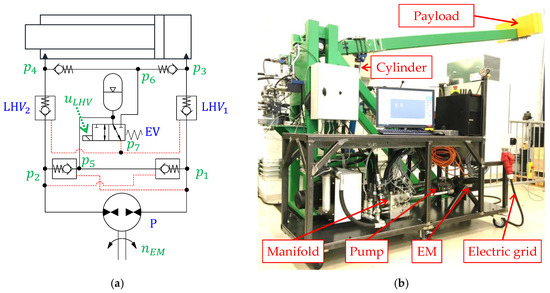
Figure 1.
(a) Simplified schematic of the self-contained cylinder; (b) the experimental setup.
2.1. Problem Statement
The control element of this electro-hydraulic system is an electric motor (EM). Its speed (nEM) is commanded to control the piston position (x) by adjusting the flow rate of the hydraulic unit (P). Such an input signal (uEM) is typically generated in two alternative ways with respect to x:
- (1)
- In open-loop (the system operator defines uEM directly, for instance using a joystick).
- (2)
- In closed-loop (an algorithm calculates uEM to track the commanded piston position based on the measured position error).
Enabling the motion of the actuator requires disengaging the load-holding valves. A reduced drop of about 1.2 mm was observed in the actuator position during this operation with closed-loop position control [21]. Such a negligible position variation is amplified when the system is operated in open-loop and might become undesired. So, this paper only considers operations in open-loop position control where uEM is obtained by using velocity feedforward (this aspect will be clarified later). The working cycle that was chosen concerned lifting the crane against a resistant load and then lowering it with an overrunning load. Knowing the desired motion (Figure 2a), the corresponding piston velocity generated the commanded motor speed (Figure 2b) using only feedforward control. Right after disengaging the LHVs (i.e., their dimensionless command becomes 1 in Figure 2c,d), the position drop of the actuator increased up to 2.5 mm when extending the piston from the position xc,0 = 50 mm (Figure 2e), or up to 4 mm before retracting the piston from xc,0 = 440 mm (Figure 2f).
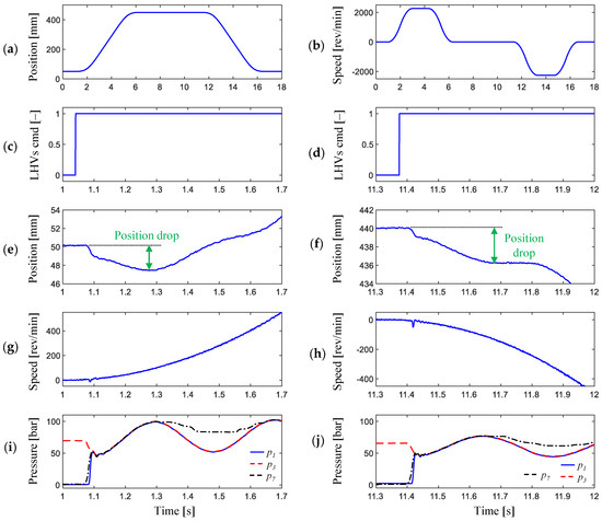
Figure 2.
A representative working cycle: (a) desired piston position; (b) resulting electric motor’s (EM) speed command; (c,d) load-holding valve’s command; (e,f) measured piston position; (g,h) measured EM’s speed; (i,j) measured pressures.
This position drop is dictated by both the dynamics of the electric motor and the difference existing between the pressures in the actuator’s piston-side chamber (p3) and in the pump’s piston-side (p1). In fact, the motor speed remained very low when the position drops took place (Figure 2g,h). The load-carrying pressure (p3) decreased (Figure 2i,j) because the initial value of the pump pressure (p1) was equal to the accumulator pressure due to the leakages in the hydraulic unit.
2.2. Improved Motion Control Strategy
The feature proposed in this paper modifies the original control strategy, as detailed in [21], to avoid the drop mentioned above in the piston position when the LHVs are disengaged. This modification of the control algorithm takes place during the transition of the LHVs from closed to open state. The idea behind this process can be described according to the following steps:
- Step 1. Right before opening the LHVs, the electric motor is controlled to build up the pump pressure on the piston-side (p1) to be equal to the actuator pressure (p3) (i.e., closed-loop pressure control is applied). Note that now the electrovalve (EV) is not energized, so the LHVs’ opening pilot (p7) remains very low and equal to the accumulator pressure (p5).
- Step 2. When the pressure difference between p3 and p1 (ePC,1) becomes smaller than a predefined threshold, the EV is energized, and the objective of the closed-loop pressure control is now compensating for the pressure difference between p3 and p7 (i.e., the EM is adjusting its speed based on the error ePC,2 = p3 − p7).
The control structure with the new pressure control (PC) function is illustrated in Figure 3. It generates the commanded electric motor’s speed (nEM) by using the feedforward signal (uFF) that involves the commanded piston velocity (e.g., vRef can be obtained from the joystick command), the bore-side area of the actuator (A), and the displacement of the hydraulic unit (D):
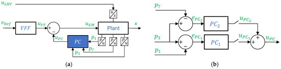
Figure 3.
(a) Proposed control structure of the self-contained cylinder for open-loop position control; (b) detail of the pressure controller.
As pointed out in [21], pressure feedback can also be included to add artificial damping and increase motion performance, especially in closed-loop position control. However, to clearly show the proposed pressure control strategy’s effect, only open-loop control without pressure feedback is presented in this paper.
Additionally, the controller PC only considers two-quadrant operations to meet the functioning dictated by the crane (i.e., the load-carrying chamber is always located on the piston-side). However, the pressure control can be expanded to also deal with high-pressure on the rod-side in case four-quadrant functioning is needed.
Pressure control is activated when the piston motion is demanded (i.e., and defines a speed command directed to the EM and consisting of two proportional parts (uPC,1 and uPC,2). Before disengaging the LHVs, the pump pressure () is built up, by activating uPC,1, to be equal to the load pressure ():
When the difference |p3 − p1|becomes less than 0.5 bar, then uPC,2 comes into play
and the LHVs are disengaged by energizing the 3/2 electrovalve
The pressure control signals (i.e., uPC, uPC,1 and uPC,2) are limited to a maximum of 1000 rpm.
3. Results and Discussion
The proposed solution to smoothly disengage the load-holding valves with open-loop position control has been experimentally tested with the working cycle presented before (Figure 2a,b). The results were compared to the original measurements in Figure 4 focusing on the initial stage of the piston extension and retraction right after releasing the load-holding valves.
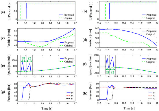
Figure 4.
A representative working cycle: (a,b) load-holding valve’s commands; (c,d) measured piston positions; (e,f) measured EM’s speeds; (g,h) measured pressures.
Due to the action of the pressure control, the commands to disengage the LHVs were slightly postponed compared to the original scenario (Figure 4a,b) in order to build up the pump side pressure () to be equal to the actuator pressure (), i.e., pressure control step 1 (S1). Since S1 was not enough to eliminate the drop in the piston position (i.e., a 0.7 mm drop still occurred), a second control step (S2) was added to make sure that the EM was actively controlled when the opening of the LHVs took place. Thus, the LHVs were disengaged smoothly and the drop in the piston position was eliminated (Figure 4c at about 1.14 s and Figure 4d around 11.45 s). The intervention of the prime mover (Figure 4e,f) built up the pressure on the pump port (Figure 4g,h).
4. Conclusions
This paper proposed and experimentally validated a method to smoothly disengage the load-holding valves of a self-contained electro-hydraulic cylinder driving a single-boom crane. The approach involves pressure control and eliminates the piston position’s drop that takes place right after energizing the load-holding valves (drops up to 4 mm were observed). These outcomes benefit those systems where the kinematics amplify the piston motion significantly (e.g., in aerial platforms) increasing, therefore, the operational safety. Motion control in open-loop was considered in this research. However, future work will address the disengagement of the load-holding valves smoothly when closed-loop position control is required.
Author Contributions
Conceptualization, D.H. and D.P.; methodology, D.H.; software, D.H.; validation, D.H.; formal analysis, D.H.; investigation, D.H.; data curation, D.H.; writing—original draft preparation, D.H. and D.P.; writing—review and editing, D.H., D.P.; visualization, D.H.; supervision, D.P. All authors have read and agreed to the published version of the manuscript.
Acknowledgments
The authors acknowledge the funding through the Norwegian Research Council projects Motion Lab (245717/F50) and SFI Offshore Mechatronics (237896).
Conflicts of Interest
The authors declare no conflict of interest.
Abbreviations
The following abbreviations are used in this manuscript:
| EM | electric motor |
| EV | electrovalve |
| LHV | load holding valve |
| P | hydraulic unit |
| PC | pressure control |
| VFF | velocity feedforward |
| p | pressure |
| nEM | angular speed of the electric motor |
| x | piston position |
| v | piston velocity |
| u | command |
| k | constant gain |
References
- Padovani, D.; Rundo, M.; Altare, G. The Working Hydraulics of Valve-Controlled Mobile Machines: Classification and Review. ASME J. Dyn. Syst. Meas. Control 2020, 142, 070801. [Google Scholar] [CrossRef]
- Rahmfeld, R.; Ivantysynova, M. Energy Saving Hydraulic Actuators for Mobile Machines. In Proceedings of the 1st Bratislavian Fluid Power Symposium, Casta-Pila, Slovakia, 2–3 June 1998; pp. 177–186. [Google Scholar]
- Michel, S.; Weber, J. Energy-efficient Electrohydraulic Compact Drives for Low Power Applications. In Proceedings of the ASME/BATH Symposium on Fluid Power Motion Control, Bath, UK, 12–14 September 2012. [Google Scholar]
- Pedersen, H.; Schmidt, L.; Andersen, T.O.; Brask, M.H. Investigation of New Servo Drive Concept Utilizing Two Fixed Displacement Units. Int. Symp. Fluid Power 2014, 8, 1–9. [Google Scholar] [CrossRef]
- Schmidt, L.; Roemer, D.; Pedersen, H.; Andersen, T. Speed-Variable Switched Differential Pump System for Direct Operation of Hydraulic Cylinders. In Proceedings of the ASME/BATH Symposium on Fluid Power and Motion Control, Chicago, IL, USA, 12–14 October 2015. [Google Scholar]
- Schmidt, L.; Groenkjaer, M.; Pedersen, H.; Andersen, T. Position Control of an Over-Actuated Direct Hydraulic Cylinder Drive. Control Eng. Pract. 2017, 64, 1–14. [Google Scholar] [CrossRef]
- Minav, T.; Heikkinen, J.; Pietola, M. Direct Driven Hydraulic Drive for New Powertrain Topologies for Non-Road Mobile Machinery. Electr. Power Syst. Res. 2017, 152, 390–400. [Google Scholar] [CrossRef]
- Gøytil, P.; Padovani, D.; Hansen, M. On the Energy Efficiency of Dual Prime Mover Pump-Controlled Hydraulic Cylinders. In Proceedings of the ASME/BATH Symposium on Fluid Power and Motion Control, Longboat Key, FL, USA, 7–9 October 2019. [Google Scholar]
- Michel, S.; Weber, J. Electrohydraulic Compact-Drives for Low Power Applications Considering Energy-efficiency and High Inertial Loads. In Proceedings of the 7th FPNI PhD Symposium on Fluid Power, Reggio Emilia, Italy, 27–30 June 2012; pp. 1–18, 27–30. [Google Scholar]
- Altare, G.; Vacca, A.; Richter, C. A Novel Pump Design for an Efficient and Compact Electro-Hydraulic Actuator. In Proceedings of the 2014 IEEE Aerospace Conference, Big Sky, MT, USA, 1–8 March 2014. [Google Scholar]
- Altare, G.; Vacca, A. A Design Solution for Efficient and Compact Electro-hydraulic Actuators. Procedia Eng. 2015, 106, 8–16. [Google Scholar] [CrossRef]
- Çalışkan, H.; Balkan, T.; Platin, B. A Complete Analysis for Pump Controlled Single Rod Actuators. In Proceedings of the 10th International Fluid Power Conference, Dresden, Germany, 8–10 March 2016. [Google Scholar]
- Hagen, D.; Padovani, D.; Ebbesen, M.K. Study of a Self-Contained Electro-Hydraulic Cylinder Drive. In Proceedings of the Global Fluid Power Society PhD Symposium (GFPS), Samara, Russia, 18–20 July 2018. [Google Scholar]
- Padovani, D.; Ketelsen, S.; Hagen, D.; Schmidt, L. A Self-Contained Electro-Hydraulic Cylinder with Passive Load-Holding Capability. Energies 2019, 12, 292. [Google Scholar] [CrossRef]
- Qu, S.; Fassbender, D.; Vacca, A.; Enrique, B.; Neumann, U. A Closed Circuit Electro-Hydraulic Actuator with Energy Recuperation Capability. In Proceedings of the 12th International Fluid Power Conference, Dresden, Germany, 12–14 October 2020. [Google Scholar]
- Minav, T.; Panu, S.; Matti, P. Direct-Driven Hydraulic Drive Without Conventional Oil Tank. In Proceedings of the ASME/BATH Symposium on Fluid Power and Motion Control, Bath, UK, 10–12 September 2014. [Google Scholar]
- Schmidt, L.; Ketelsen, S.; Brask, M.; Mortensen, K. A Class of Energy Efficient Self-Contained Electro-Hydraulic Drives with Self-Locking Capability. Energies 2019, 12, 1866. [Google Scholar] [CrossRef]
- Schmidt, L.; Ketelsen, S.; Padovani, D.; Mortensen, K. Improving the Efficiency and Dynamic Properties of a Flow Control Unit in a Self-Locking Compact Electro-Hydraulic Cylinder Drive. In Proceedings of the ASME/BATH Symposium on Fluid Power Motion Control, Longboat Key, FL, USA, 7–9 October 2019. [Google Scholar]
- Ketelsen, S.; Padovani, D.; Andersen, T.O.; Ebbesen, M.K.; Schmidt, L. Classification and Review of Pump-Controlled Differential Cylinder Drives. Energies 2019, 12, 1293. [Google Scholar] [CrossRef]
- Hagen, D.; Padovani, D.; Choux, M. A Comparison Study of a Novel Self-Contained Electro-Hydraulic Cylinder versus a Conventional Valve-Controlled Actuator—Part 2: Energy Efficiency. Actuators 2019, 8, 78. [Google Scholar] [CrossRef]
- Hagen, D.; Padovani, D.; Choux, M. A Comparison Study of a Novel Self-Contained Electro-Hydraulic Cylinder versus a Conventional Valve-Controlled Actuator—Part 1: Motion Control. Actuators 2019, 8, 79. [Google Scholar] [CrossRef]
Publisher’s Note: MDPI stays neutral with regard to jurisdictional claims in published maps and institutional affiliations. |
© 2021 by the authors. Licensee MDPI, Basel, Switzerland. This article is an open access article distributed under the terms and conditions of the Creative Commons Attribution (CC BY) license (https://creativecommons.org/licenses/by/4.0/).