Abstract
Possible configurations for propulsion and electric power generation on vessels are an important field for the researcher in the naval area. The most important is electric power generation. Nowadays, diesel engines are the main prime movers, although all sorts of other electric power generating types are coming more and more. Apart from that, there are some specific high voltage/power applications that use steam or gas turbines. As well as this, wind power, either on a traditional sailing vessel or in a wind electric power generator, and also solar power, is gaining interest. The modern configuration is developing until the goal of zero carbon emissions is reached, using the electric power system configuration, introducing fuel cells as prime movers, and using batteries as energy storage devices, to increase the system’s safety.
1. Introduction
The future of ships is the electric propulsion, so more and more the ship designers are developing eco-friendly solutions (safe for the environment), with the goal of zero carbon emissions [1,2,3,4]. An electric ship is more than an electric drive system; it includes power generation, delivery, automation, and control. More and more naval applications require a larger amount of electric power generated and delivered (much more than the commercial ships), which can be used by high power consumers, high-power military loads, energy conversion systems, and a bigger delivery system. Other loads may include an electro-magnetic assistance launch system, communication, radar, sonar systems, and hospitality and service loads, as is shown in Figure 1.
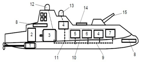
Figure 1.
Power electric warship system: 1—advanced motor and propulsor, 2—motor drive, 3—advanced generators, 4—pulse forming network, 5—energy storage, 6—actuators and auxiliaries, 7—fuel cell stacks, 8—sensors, 9—distribution, 10—integrated power system, 11—integrated thermal and power management systems, 12 and 13—radar systems, 14—electromagnetic vertical launching system, 15—electromagnetic gun.
The synchronous electric generator driven by a gas turbine or diesel engines electrically connected with an electric propulsion motor is nowadays used in a large variety of vessels. According to [1], the total installed electric propulsion power in marine vessels was in 2002 in the range of 6 to 7 GW. Azimuth thrusters and podded thrust units brought important maneuvering capabilities, control of the dynamic positioning, and intelligent applications [5,6,7]. Now, electric propulsion is applied mainly in the following types of marine vessels: cruise vessels, ferries, dynamic positioning drilling vessels, cargo vessels, moored floating production facilities equipped with thrusters, shuttle tankers, cable layers, pipe layers, icebreakers and other ice going vessels, supply vessels, submarines, combatant surface ships, and unmanned underwater vehicles.
The scientific literature [1,8,9,10] mentions that the expected compound annual increasing, for the electric engines and electric generators for ship propulsion systems, is expected to be around 20%. Today, almost all the cruise ships and a lot of cargo ships changed to electric motor propulsion systems. For example, the largest marine electric motors are installed on cruise vessel passenger liner Queen Elizabeth 2, which has a redundant system of propulsion—44 MW, 144 RPM, 60 Hz salient pole synchronous motors—driving the propeller shafts. The dimensions of the motors are 9 m in diameter, weighing more than 400 t each. The installed electric power is 95 MW, produced by nine three-phase 10.5 MW, 10 kV, 60 Hz salient pole synchronous generators—electric driven by diesel engines. The vessel is one of the largest, longest, tallest, widest, and most expensive passenger cruise vessels. Its power plant includes gas turbines and diesel engines that produce 118 MW of electricity, enough to power a city of 300,000 people. Most of the produced power is used for the propulsion system; each of the electric motors draws 21.5 MW during full power and it has Rolls Royce Mermaid pod propulsors, two fixed and two azimuths rotating 360°.
2. Propulsion and Electric Power Network
The naval system configurations for ship propulsion are presented below [4,5,6,11].
- Direct diesel propulsion, as shown in Figure 2a, uses electric power generated and distributed by a separated auxiliary system, gearbox reduction and fixed/controllable pitch propellers, and steerable thrusters with fixed/controllable pitch propellers.
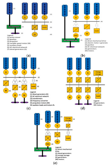 Figure 2. Naval configurations of the propulsion and electric power system, Direct diesel (a), Hybrid diesel electrical (b,e), Electric diesel (c,d).
The direct propulsion is the most common and basic configuration used still for many operating profiles because when the auxiliary power is a part of the propulsion power needed, there is no benefit in the combination of the propulsion and energy. Vessels like bulk, container carriers, or multipurpose have this direct configuration.
- Hybrid diesel electrical, as shown in Figure 2b,e, uses direct propulsion, integrated electric power generation and distribution, gearbox reduction and fixed/controllable pitch propellers, and steerable thrusters with fixed/controllable pitch propellers.
The hybrid configuration combines the advantages of combined propulsion and energy at a lower sailing speed, improving the carbon emissions goal and the efficiency (less power losses) of a diesel direct drive at higher speed.
- Electric diesel propulsion, as shown in Figure 2c,d, uses integrated electric power generation and distribution, gearbox reduction and fixed/controllable pitch propellers, and steerable thrusters with fixed/controllable pitch propellers.
The main switchboard power delivery system uses AC voltage, as shown in Figure 2c, or CC voltage, as shown in Figure 2d; in the second case, the power system is safer using the advantage of the energy storage system. There are many reasons for this type of system—better ship design, better power efficiency and reduction of emissions, better comfort from reduction of vibrations and noise, reduction of the maintenance of mechanical components, and more flexible operability.
- Direct diesel propulsion by shaft uses electric power, which can be also generated by driven shaft generators, as shown in Figure 2b,e, and a separated or integrated auxiliary system, with gearbox reduction and controllable pitch propellers, and steerable thrusters with controllable pitch propellers.
The propulsion with shaft configuration is mainly applied on vessels with an important power consuming process. When the process is not operated during sailing at maximum speed, then this mechanical combination of propulsion and power is more efficient for investment, fuel consumption, and emissions for container vessels or heavy lift ships. For separated or integrated main and auxiliary electrical power systems, the goal is the efficiency of the prime movers and the availability of the ship’s electric network. The shaft generator is mostly operated at synchronous speed, but permanent magnet machines and power electronic converters allow generation at variable speed, so a hybrid diesel electrical configuration can be examined, allowing electric drive as well.
Table 1 and Table 2 give a synthetic overview of the naval system configurations for ship propulsion [12]. Presented are the types of ships that match with different types of propulsions, advantages and disadvantages of the propulsion and power systems on vessels, and installed power and parameters.

Table 1.
Trends for configuration of propulsion and power supply architecture on vessel types.
Table 2.
Advantages and disadvantages of propulsion and power supply technologies on vessels [12].
3. Aspects of the Air Emission Configuration Reduction
Only for the electric propulsion configuration the goal of zero carbon emissions is achievable if the diesel engine is replaced with the renewable power generation, like the fuel cell [12,13]. Hybrid fuel cell propulsion, and integrated electrical energy generation and distribution, with steerable thrusters with fixed pitch propellers, uses as the prime movers the fuel cells instead of diesel engines. There is a limited operating time, so for now it is used in the inland vessels.
The configuration is hybrid because of the direct online connected power battery. The advantages to the fuel cells are: zero emission for the power generation, all electric ship, and high redundancy because of the multi-functional power battery.
The air emissions coming from the combustion motors can be of different types. Substances, like NOx, SOx, and particulate matter (PM 2.5 and 10 μm), are regulated by the Maritime Environmental Pollution Committee—MEPC of the International Maritime Organization—IMO, the European Union, the Environmental Pollution Agency—EPA of the United States of America, and by local governments. The design is influencing only the PM type. For greenhouse gases, the IMO is involved in the reductions of CO2 emissions. The issues are also economical, like improvement of fuel efficiency, future fuel prices may also include additional carbon prices, such as future capitalization of CO2 emissions at a current approximate rate of EUR 22/t.
The ways to achieve the green ship power system goal, from a design point of view, are several. The traditional configurations for electric power generation, distribution, and consumption can be improved by the reduction of consumption, improving efficiency for the auxiliary equipment, LED lighting and intelligent consumption/control systems, and power management systems. For the electric propulsion design, changes involve the complete drive train and changing the hull shape, which are going to see the efficiency growing up to 40%. The potential for improvement of energy efficiency is clear from the efficiency diagram for the example of a container vessel sailing at 24 knots, as shown in Figure 3 [5,13]. We can consider that the prime mover can partially or completely be replaced by green renewable sources, wind or sun power, or by energy carriers like H2. When applying H2, the local energy conversion will be done with fuel cells.
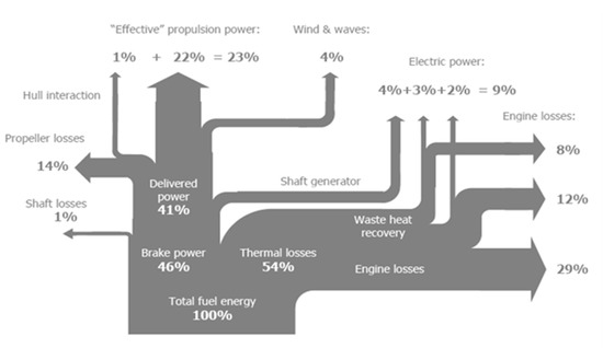
Figure 3.
Efficiency diagram (Sankey diagram) for a container vessel, according to [13].
Electric diesel, hybrid electric diesel, and hybrid fuel cell power systems have a big power delivery system for the transportation and distribution of the main power [13,14]. The main delivery can use AC or DC voltage, low or medium voltage, with a maximum power rating; for example, an application of low voltage has 5 MWe. Selecting AC or DC is mainly a matter of energy losses; for example, if many frequency control power consumers are needed for gaining efficiency in power consumption, a DC voltage power system implementation will prevent the double conversion AC-DC and DC-AC, saving up to 5% in efficiency. Because DC voltage power systems do not have reactive power, they can be a smaller size. They do not need phase synchronization during parallel operation of generators. As fuel cells and batteries produce DC voltage, it seems logical to select DC for the main power delivery of a fuel cell propulsion system. We also have to take into account that DC voltage systems are less easy to protect for overload and short-circuit, so ultra-rapid fuses are needed. Furthermore, DC voltage power systems need more care than AC voltage power systems, which concerns safety for humans and the machine.
The developing of hybrid diesel electric propulsion, power saving devices in the auxiliary grid like frequency converters, AC voltage switching power supplies, increasing application of LED lighting, and the electric network suffers more and more from current and voltage distortion and from increase of the zero sequence currents. Because the power system is an isolated one, it is more sensitive to the non-linear and the unbalanced loads, and for transient regimes caused by switching, so there is a need for extra attention to electric power systems design, to electromagnetic compatibility (EMC) and earthing. Figure 4 shows a simulation for switching on 950 kW in the electrical network of a mega yacht, presenting the total harmonic distortion on the system voltage, which is going to 9% and is too high. For preventing such a distortion, adding 12-pulse transformers supplying the frequency converter is a solution.
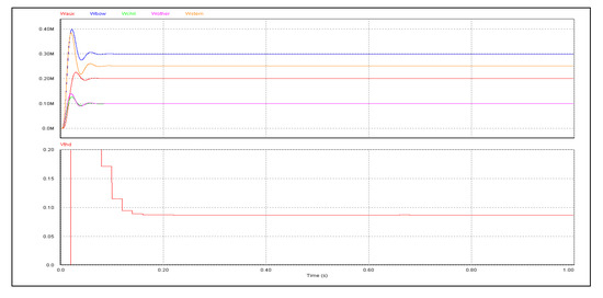
Figure 4.
The total harmonic distortion on the system voltage by simulating the switching on of the auxiliary power system of a mega yacht, according to [13].
4. Conclusions
The overview of the ship design architecture, for the isolated power system of a vessel, is pointing to the architecture with less air pollution effects, which is a feasible solution offered by the electric diesel with the total or partial fuel cell power supply. Fuel cell power generation can be considered from a shipbuilding point of view if the ship’s design process can provide an optimized system solution with a DC voltage electric network and a minimum of negative effects on the protection and safety on the network. Operating profiles have to give answers to the following questions: Does the operating speed profile justify the selection of an electrical diesel power system and propulsion? Can the electric power and energy system be supplied by fuel cells? The proposed solution depends also on the operating fuel consumption and the load characteristic of the prime movers with respect to the functional safety of the ship, but also to the maximal environmental pollution reduction.
Conflicts of Interest
The author declares no conflict of interest.
References
- Gieras, J. Naval electric machine. Advancements in Electric Machines; Springer: Dordrecht, The Netherlands, 2008; pp. 213–234. [Google Scholar]
- Chalfant, J. Early-stage design for electric ship. Proc. IEEE 2015, 103, 2252–2266. [Google Scholar] [CrossRef]
- Dennis, T. Practical Marine Electrical Knowledge, 3rd ed.; Witherby-Seamanship International: Livingston, Scotland, 2014. [Google Scholar]
- International Maritime Organization. SOLAS: Consolidated Text of the International Convention for the Safety of the Life at Sea; Int. Maritime Org: London, UK, 2014. [Google Scholar]
- Borstlap, R.; Ten Katen, H. Ships’ Electrical Systems; Dokmar Maritime Publishers B.V.: Enkhuizen, The Netherlands, 2011. [Google Scholar]
- Van Dokkum, K. Ship Knowledge: A Modern Encyclopedia, 1st ed.; Publisher Dokmar: Vlissingen, The Netherlands, 2003. [Google Scholar]
- Van Dokkum, K. Ship Knowledge: Types of Ships and Their Trades; Publisher Dokmar: Vlissingen, The Netherlands, 2003. [Google Scholar]
- Carlton, J. Marine Propellers and Propulsion; Elsevier: Amsterdam, The Netherlands, 2011. [Google Scholar]
- Ferrante, M.; Chalfant, J.; Chryssostomidis, C.; Langland, G.; Dougal, R. Adding simulation capability to early-stage ship design. In Proceedings of the 2015 IEEE Electric Ship Technologies Symposium (ESTS), Alexandria, VA, USA, 21–24 June 2015; pp. 207–212. [Google Scholar]
- Menis, R.; da Rin, A.; Sulligoi, G.; Vicenzutti, A. All electric ships dependable design: Implications on project management. In Proceedings of the 2014 AEIT Annual Conference—From Research to Industry: The Need for a More Effective Technology Transfer (AEIT), Trieste, Italy, 18–19 September 2014; pp. 1–6. [Google Scholar]
- Maggioncalda, M.; Gualeni, P.; Notaro, C. Life Cycle Performance Assessment (LCPA) Tools. In Optimisation of Ship Design and Operation for Life Cycle; Springer: Berlin, Germany, 2014; Volume 1. [Google Scholar]
- Geertsmaa, R.D.; Negenborna, R.R.; Vissera, K.; Hopmana, J.J. Design and control of hybrid power and propulsion systems for smart ships: A review of developments. J. Appl. Energy 2017, 194, 30–54. [Google Scholar] [CrossRef]
- Krijgsman, B.M. Propulsion and energy optimization for ships an optimal propulsion and electrical energy concept. In Proceedings of the Second International Symp on Electrical and Electronics Engineering, Galati, Romania, 12–13 September 2008. [Google Scholar]
- Nijland, M.; Van Beek, T. Efficiency improvement related to propeller-rudder interaction. In Proceedings of the 5th Annual Green Ship Technology Conference, Rotterdam, The Netherlands, 11–12 March 2008. [Google Scholar]
Publisher’s Note: MDPI stays neutral with regard to jurisdictional claims in published maps and institutional affiliations. |
© 2020 by the author. Licensee MDPI, Basel, Switzerland. This article is an open access article distributed under the terms and conditions of the Creative Commons Attribution (CC BY) license (http://creativecommons.org/licenses/by/4.0/).