Abstract
In this paper, a novel monolithic structural design of a piezoelectric (PZT) inchworm motor utilizing three force amplification mode (FAM) mechanisms is presented as an approach to overcome the design challenges of common PZT inchworm motors. A mechanical system model based on Simulink software was developed for a proposed inchworm motor design. The dynamic response of the motor was simulated at the moment of releasing the pre-stressed mechanism. The results showed a backlash response due to the mass acceleration of the mechanisms.
1. Introduction
Piezoelectric inchworm linear motors are common devices in high precision positioning applications, such as in optical equipment and precision manufacturing. Inchworm motors can be realized with one or multiple piezoelectric (PZT) stacks. The positioning of an object is performed either by the direct contact of PZT elements that are functioning in shear mode [1,2], or by indirect contact through flexural mechanisms, where the PZT elements are functioning in normal mode [3,4]. The main advantage of using a flexural mechanism is to enhance the reliability of the PZT element against damage. Fortunately, flexural mechanisms can also be designed to amplify the generated displacement or force by the PZT stack, for example, by applying a mechanical lever design concept. However, miniaturization, large-force actuation capability, large internal stresses, fragile flexural design based on lever concept and a requirement for high precision manufacturing are the main challenges for realizing PZT inchworm motors based on an amplified mechanisms design.
The new design consists of three main integrated mechanisms, such that each is driven by a single PZT element. The two-clamping mechanisms are initially confined by a mechanical guidance and are released when the corresponding PZT element is electrically polarized. The other mechanism is centered between the clamping units and performs device stretching when the corresponding PZT element is electrically polarized.
2. Methods
2.1. Structural Design and Operation Concept
The top view of the initially clamped inchworm motor based on force amplification mode (FAM) mechanisms is shown in Figure 1. The piezoelectric inchworm motor consists of three main units, two for clamping function and one for extending function. The clamping units are confined by mechanical guidance to provide an initial clamping condition. The mechanism at the center of the motor is responsible for providing the extending function.
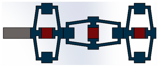
Figure 1.
Top view of a piezoelectric inchworm motor based on force amplification mode (FAM) design.
Each mechanism consists of a flexural structure and a piezoelectric stack placed at the center of the mechanism. When the piezoelectric stack is electrically polarized, a corresponding expansion deformation occurs in the axis of the piezoelectric stack force, while compression deformation occurs in the normal angle to the axis of the piezoelectric stack force.
A motor stroke is generated by the cooperative work of the three mechanisms. Initially, the motor is clamped by the mechanical guidance. When the piezoelectric stack of one clamping unit is electrically polarized, then the mechanical contact of the mechanism is detached from the mechanical guidance. At this moment, the piezoelectric stack of the central mechanism (extending mechanism) is electrically polarized. This will pull the released clamping unit toward the central mechanism. After that, the clamping unit is returned to mechanical attachment with the mechanical guidance by electrically deactivating the corresponding piezoelectric stack. Then, the other clamping unit is detached from the mechanical guidance, and the piezoelectric stack of the central mechanism is now electrically deactivated to allow the mechanism to return back to the initial mechanical condition, which also results in the mechanical translation of the recently released clamping unit before it is returned back to mechanical clamping status. This process is repeated for further stroke actuation in order to achieve a longer distance actuation.
2.2. System Modelling and Boundary Conditions
The presented inchworm motor can be modelled based on three coupled oscillating masses, as shown in Figure 2. The model was developed to study the dynamic response of the motor at the extending status; i.e., the piezoelectric stacks of clamping unit 1 and the extending unit (central mechanism) are initially activated. When the piezoelectric stack of the extending unit is deactivated, the stored elastic energy will be released, causing the acceleration of the three mass blocks. The stored elastic energy is defined by the initial mechanical deflection (SA) and stiffness constant (K) of each mechanical spring.
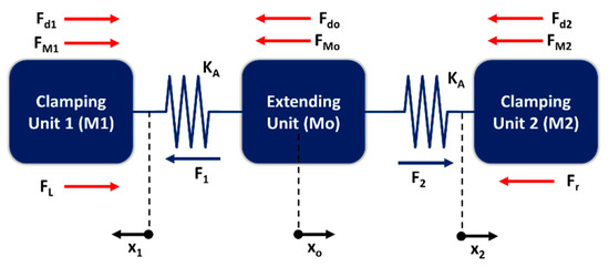
Figure 2.
Mass–Spring model of force amplification mode (FAM) piezoelectric inchworm motor.
The coupled oscillating mass model can be mathematically represented by:
The parameter values of the stiffness constant (KA) and the initial displacement (SA) of elastic elements depend on the structural design of the mechanical advantage mechanism and the electromechanical characteristics of the applied PZT element. The specific structural design of the mechanical advantage mechanism is not the focus of this work; therefore, arbitrary values will be selected to apply a force amplification mode. In this work, a PZT element with a 1.25 μm stroke at 125 N of generated force was arbitrarily assumed. Accordingly, the SA and KA values are 0.125 μm and 10 GN/m for a FAM design with a mechanical advantage factor of 10. A mass magnitude of 0.2 g was selected for the three mass blocks. The damping coefficient was set to 100 N·s/m. A friction force of 200 N was assumed at the clamping unit 2. The equations of the model were solved based on the Simulink model in Figure 3.
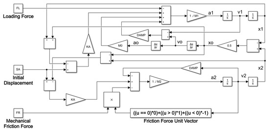
Figure 3.
Simulink block diagram of the mechanical model of the piezoelectric inchworm motor.
3. Results and Discussion
The dynamic mechanical response of the inchworm motor is shown in Figure 4. The final stroke is a result of the vector summation of deflections of all mass components. The release of elastic energy affects both the clamping and the loading mass blocks, such that deflection in both directions is observed. This response reduces the final stroke of the inchworm motor.
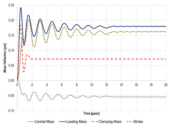
Figure 4.
Displacement simulation results of a FAM piezoelectric inchworm motor under 200 N friction force and zero loading force.
4. Conclusions
A monolithic design of a piezoelectric inchworm motor initially clamped by a mechanical guidance was proposed in this paper. The main advantage of the new design is that all mechanisms for the clamping and extending function are based on the force amplification mode design concept. The mechanical system model based on Simulink software showed that a stroke of 203 nm was applied against 200 N of mechanical friction. However, a backlash response was also observed due to the mass oscillation of all mechanisms of the proposed inchworm motor. The effect of applying different mass amounts on the backlash response could be a key design solution for overcoming such backlash.
Funding
This project is funded by the Federal Ministry of Education and Research (BMBF) in Germany under the umbrella of Connected Health in Medical Mountains (CoHMed) of Furtwangen University with grant number 13FH5I01IA.
Conflicts of Interest
The founding sponsors had no role in the design of the study; in the collection, analyses, or interpretation of data; in the writing of the manuscript, and in the decision to publish the results.
References
- Huang, H.; Wang, Y.W. Design and Experimental Research of a Rotary Micro-Actuator Based on a Shearing Piezoelectric Stack. Micromachines 2019, 10, 96. [Google Scholar] [CrossRef] [PubMed]
- Zhao, B.; Fang, R.; Shi, W. Modeling of Motion Characteristics and Performance Analysis of an Ultra Precision Inchworm Motor. Materials 2020, 13, 3976. [Google Scholar] [CrossRef] [PubMed]
- Ma, L.; Jiang, C.; Xiao, J.; Wang, K. Design and Analysis of a Piezoelectric Inchworm Actuator. J. Micro-Bio Robot. 2014, 9, 11–21. [Google Scholar] [CrossRef]
- Chen, X.; Li, M.; Zhang, H.; Lu, Q.; Lyu, S. Improvement on the Structure Design of a Kind of Linear Piezoelectric Motor with Flexible Drive-Foot. Int. J. Precis. Eng. Manuf. 2020, 21, 81–89. [Google Scholar] [CrossRef]
Publisher’s Note: MDPI stays neutral with regard to jurisdictional claims in published maps and institutional affiliations. |
© 2020 by the author. Licensee MDPI, Basel, Switzerland. This article is an open access article distributed under the terms and conditions of the Creative Commons Attribution (CC BY) license (https://creativecommons.org/licenses/by/4.0/).