Abstract
The knowledge of loads acting on Running Specific Prostheses (RSP), and in particular, on Running Prosthetic Feet (RPF) is crucial for evaluating the athlete’s running technique, designing RPF, and developing models of the runners. The aim of this work was to develop a set of instrumented RPF (iRPF) suitable for track data collection of start, sprinting, and whole run-in and take-off of long jump. The system allows measuring with a portable data logger forces acting on the foot clamp on multiple steps of the athlete without modifying the RSP behavior: The method involves strain gauge bridges applied to each RPF in a configuration that allows decoupling the loads parallel and normal to the foot clamp during the stance phase. Comparison with literature data and validation against force platform data gave confirmation of the validity of the method in the estimation of determinants of sprint performance.
1. Introduction
Running Specific Prostheses (RSP) are assistive technologies used by Paralympic sprint runners and long jumpers to reach their maximal performance. Considering athletes with transtibial amputation (TT), the Running Prosthetic Foot (RPF) is directly clamped to the socket. In the case of transfemoral amputees (TF) or knee-disarticulated athletes (KD), the RPF is connected via a pylon to the knee that, in turn, is connected to the socket. RPF can typically be J-shaped or C-shaped: Loads acting on the RPF come from Ground Reaction Forces (GRF) and reach the leg through a complex combination of loads parallel and normal to the prosthetic pylon/socket assembly. Since their introduction, researchers have focused not only on the properties of Running Prosthetic Feet (RPF) but also on the nature of loads that the ground applies through the foot to the leg and eventually to the athlete’s body [1,2,3,4]
There is a vast literature on sprint running and long jumping performances both for able-bodied and Paralympic athletes. In general, studies which focused on the sprint efficiency of running, measured the GRF along the run [5] on a set of force platforms embedded in the floor [1,6]. Most of these studies were completed indoor, on elite athletes performing their sprint or jump on force platforms. Two approaches are reported: In the first approach, the GRF was captured together with the kinematics on a single or double step over the platforms. Two representative papers are those by Bruggerman et al. [1] and Makimoto et al. [6]. The study by Nagahara et al. [5] is representative of the second approach, in which a large set of plates is used. Specifically, Nagahara adopted over 50 force platforms and 60 motion capture cameras installed in the runway of an indoor track. The limitations of these approaches are the collection of a single step, in the first approach, and the need of a very expensive and unique installation, in the second approach. In both cases, there is a lack of data regarding all steps and possibly curve running. To overcome these limitations, the aim of this work was to develop a set of instrumented and calibrated RPF suitable for measuring the structural loads acting at the RPF clamp on the sagittal plane during the whole sprint with a wearable approach.
2. Materials and Methods
2.1. Development of the Instrumented Running Prosthetic Foot (iRPF)
Firstly, a nomenclature was introduced to distinguish loads acting on the RPF when expressed in the Global (Figure 1a), in the Foot (Figure 1b) or in the Socket (Figure 1c) reference frames. Loads from a force platform are referred to as the Global Reference Frame, where XG is horizontal and YG is vertical. The Foot reference frame is embedded on the instrumented RPF. Its orientation relative to the socket (TT amputees) or to the pylon (TF and KD) can change due to the alignment adjustments that orthopedic technicians can apply. The orientation of the XF, YF axis can change from a J-shaped (Figure 1b) to a C-shaped (Figure 2c) foot. The Socket Reference Frame is, in turn, referable to the body’s anatomical segments, like the shank or the thigh, provided that the stomp relative motion can be taken into account. The instrumented Running Prosthetic Foot (iRPF) was developed after identifying its functional requirements: (i) Maximum number of load components, (ii) high decoupling of load component measurements, (iii) minimum weight (<0.15 kg) and disturbance to the athlete. Given these requirements, rather than adding a multiaxial load cell at the RPF clamp, we decided to let each athlete use his/her own RPF and to apply strain gauge bridges to the feet. Two strain gauge pure bending bridges were applied to the straight portion of the upper stiffer part of the foot. The third pure bending bridge was placed on the curved portion of the blade (Figure 2a,b). The position of the three bridges decoupled the effect of forces FyF and FxF, that are respectively along the yF axis (i.e., the reference axis of the foot) and perpendicular to it. In addition, the bridges also allowed to calculate the bending moment MF acting on the foot reference point, typically assumed in correspondence to the foot proximal clamp, as shown in Figure 2c.

Figure 1.
Reference Frames adopted to express the Ground Reaction Forces (GRF) components (a) Global Reference Frame and GRF components, (b) Foot reference frame and GRF components, (c) Socket reference frame and GRF components.
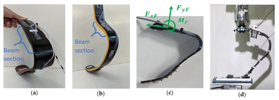
Figure 2.
Development and calibration of the instrumented RPF: (a) Strain gauge bridges applied to a C shaped Ottobock Runner Cat3 RPF, (b) bridges applied to a J shaped Ossur Cheetah Xtreme cat5, (c) load components obtained by decoupled measurements at the iRPF reference point, (d) calibration of the iRPF on a multicomponent test bench [7].
The calibration of the iRPF took place on a multicomponent test bench developed for the project and described in [7]. Each iRPF was clamped at a known position on a 6-axis load cell. Loads were applied in yF direction by a vertical slide supporting the load cell, moved by a servo-hydraulic cylinder, while the tip of the foot was supported on a horizontal floor connected to a 3-axis load cell (Figure 2d). The horizontal floor position was, in turn, controlled by a horizontal cylinder enabling to produce free translation, null translation, or given forces (measured by the 3-axis load cell). The bending moments at the three bridges were measured by the knowledge of loads at the 6-axis load cell and the knowledge of bridges instantaneous location with a motion capture system: The bridge output was measured with a portable data logger Somat EDAQ.
Four feet were instrumented: Two Ottobock 1E91 Standard Runner, Cat 3 and Cat 4, and two Ossur Cheetah Xtreme Cat 5 and Cat 7. For each foot, a single cable coming from the foot was deployed and strapped to the limbs to be finally connected to the data logger placed on a backpack. In this way, the added mass of the sensing system was lower than 100 gr, fulfilling the initial requests.
2.2. Field Tests
Field tests were carried out on an instrumented, outdoor athletic track (Budrio, Italy): The track was equipped with a Kistler 600 × 400 mm force platform (5 kHz), embedded at 60 m from the start of the long jump run-in track or at the take off board. Sprint and running events were then performed with athletes from the Italian national team. Together with the force platform, two Sony High Speed cameras were used to capture the steps over the platforms and the Optogait system (Microgate, Italy) was used in the tests to capture spatio-temporal parameters of running (Figure 3).

Figure 3.
Field tests setup: (a) Inertial suit from Xsens applied to the athletes, with detail of the RPF arrangement of sensors, (b) running validation tests with simultaneous collection of GRF from a force platform in the track and the iRPF. (c) Sprint tests on track without force platforms.
The athletes wore the Xsens Moven suit in order to capture the absolute orientation of the foot during stance: The application to an amputee runner required some adaptations. With athlete KD2 (who suffered a knee disarticulation), the Upper LEG Left was placed on the THIGH, the Lower LEG Left on the FOOT proximal end and the FOOT Left was applied to Left FOOT distal end. This implied that the Lower LEG Left described the orientation of the iRPF and, interestingly, the (virtual) Left Ankle Joint represented the sagittal angular deflection of iRPF under realistic running conditions. Structural data were collected on a GET M40 portable data logger from Athena (Longare, IT) at 500 Hz per channel, whereas the Xsens inertial suit collected samples at 240 Hz. The total added mass on a backpack worn by the athletes was 2.3 kg.
3. Results
Regarding calibration tests, the bridges’ response was linear (R2 min 0.995), cross-talk under combined loads was minimal and loads FxF, FyF and MF could be estimated with an accuracy of 3%.
The results from field tests were firstly compared to the literature, to preliminary assess their validity. GRF components in the Global Reference Frame obtained from Elite sprinters in the present study and those available from literature data are reported in Figure 4. The GRF in the vertical YG and horizontal XG direction are plotted for the intact (blue) and affected (red) limb. The shape of the normalized curves for both the intact and affected limbs resulted similar between literature data (male subject of about 100 kg) and data collected from athlete KD1 (female subject of 60 kg) in the present study, confirming the top skill level of the athletes involved.
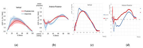
Figure 4.
GRF components in the Global Reference Frame for Elite sprinters: Literature data and present study: (a,b) GRF in the vertical YG and horizontal XG direction for the intact (blue) and affected (red) limb as in [6], (c,d) GRF in the vertical and horizontal direction from athlete KD1.
The second set of results consists in the dynamic validation tests of the iRPF, by comparing the GRFs measured with the force platform and those obtained with the iRPF during a running test of athlete KD2 on a force platform (Figure 5). Force components collected in the Foot reference system from the iRPF (Figure 5a) are combined with the absolute orientation angle of the Foot reference system obtained by the Xsens Moven suit during the step over the force platform (Figure 5b). This allows to resolve the forces from the iRPF in the Global Reference Frame and to plot together the GRF measured by the Kistler force platform at the passage of the athlete (Figure 5c) and those from the iRPF. In Figure 5d, the X and Y GRF components obtained from the force platform measurement (dotted) and the iRPF loads resolved in the Global Reference Frame (solid) are plotted together, showing a good agreement. The RMSE between the loads estimated by the iRSP and the force platform GRF resulted of 5% in vertical direction and 9% in horizontal.

Figure 5.
Dynamic validation of the iRPF by comparing GRF measured with the force platform and with the iRPF during a running test of athlete KD2: (a) Force components in the Foot reference system, collected from the iRPF, (b) absolute orientation angle of the Foot reference system obtained by the Xsens Moven suit during the step over the force platform, (c) GRF measured by the Kistler force platform at the passage of the athlete. (d) Comparison of X and Y GRF components between the force platform measurement (dotted) and the iRPF loads resolved in the Global Reference Frame.
The application of iRPF to a full run allowed to collect 12 steps in the Global Reference Frame over the sprint test (Figure 6), including step 6 during the acceleration phase, step 8 over the Kistler force platform and step 11 during the deceleration phase. The analysis of horizontal components shows differences between the area below the x axis (Braking Impulse) and the area over the x axis (Propulsive Impulse) across the steps [5,8]. The iRPF allows the calculation of the horizontal impulse from the affected limb and the comparison between a sprint aiming to the force platform (Run 10, platform on step 8) and a free sprint on track (Run 12). As it can be appreciated from Figure 7, the horizontal impulse measured during all steps of sprint test Run 10 aiming to hit a force platform is predominantly negative, whereas the horizontal impulse measured in a free sprint test aiming to best run time (Run 12) shows a predominantly propulsive impulse.

Figure 6.
The application of iRPF for multiple-step GRF collection: In the Global Reference Frame collected over the 12 steps of a sprint test, including step 8 on the force platform, (a) step 6 during the acceleration phase, (b) step 8 over the force platform, (c) step 11 during the deceleration phase.
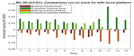
Figure 7.
Comparison of the Horizontal Impulse from the affected limb calculated with the iRPF during a sprint aiming to the force platform (step 8) and a free sprint: All steps of a free sprint test on track (Run 12, “Track”) in dark colors, all steps of a test aiming to a Force platform (Run 10 “Platform”) in light.
4. Discussion
The aim of the work was the development of a set of instrumented RPF for collecting structural loads acting on the Running Prosthetic Feet during track tests. The knowledge of loads acting on RSPs is an essential information for (i) evaluating the athlete’s running technique, (ii) designing RSP with appropriate structural properties, and (iii) developing models of the runners in order to optimize the sprint or jump performance. Loads collected on the force platform resulted in good agreement with available data from literature [6]. The original contribution of the present work consists in the possibility of collecting multiple steps during a real sprint without the need of embedding several force platforms in the track like in [1,2,5,6] but still measuring the main determinants of performance like the horizontal impulse from the affected limb [5,6,8]. The main limitation is that only the affected limbs can be studied, whereas using force platforms or instrumented treadmills both sides are measured (in simulated running conditions): Accuracy of foot orientation measure is, however, crucial.
5. Conclusions
The application of strain sensors to the RSPs and their accurate calibration allowed collecting not only a single step on a force platform embedded in the ground, but also all the steps of a real sprint event. The set of RPF instrumented with three strain gauge bridges was calibrated to predict loads acting at the RPF clamp with a static accuracy of 3%. At present, only sagittal loads can be collected: The application of torsion bridges allows for the extension of the study to curve running.
The comparison between the GRF measured on a platform and the GRF predicted by the instrumented RPF, after converting the loads measured in the RPF frame of reference into the absolute ground reference system, gave dynamic validation to the method, RMSE errors being 5% and 9% in vertical and horizontal directions. The approach was used to collect track loads over all the steps of real straight sprint tests performed by the athletes.
Acknowledgments
Thanks INAIL for supporting the research and the athletes of Italian National team.
Conflicts of Interest
The authors declare no conflict of interest.
References
- Brüggemann, G.; Arampatzis, A.; Emrich, F.; Potthast, W. Biomechanics of double transtibial amputee sprinting using dedicated sprinting prostheses. Sports Technol. 2008, 1, 220–227. [Google Scholar] [CrossRef]
- Grabowski, A.M.; McGowan, C.P.; McDermott, W.J.; Beale, M.T.; Kram, R.; Herr, H.M. Running-specific prostheses limit ground-force during sprinting. Biol. Lett. 2009, 6, 201–204. [Google Scholar] [CrossRef] [PubMed]
- Weyand, P.G.; Bundle, M.W.; McGowan, C.P.; Grabowski, A.M.; Brown, M.B.; Kram, R.; Herr, H. The fastest runner on artificial legs: Different limbs, similar function? J. Appl. Physiol. 2009, 107, 903–911. [Google Scholar] [CrossRef] [PubMed]
- Hobara, H.; Baum, B.S.; Kwon, H.-J.; Miller, R.H.; Ogata, T.; Kim, Y.H.; Shim, J.K. Amputee locomotion: Spring-like leg behavior and stiffness regulation using running-specific prostheses. J. Biomech. 2013, 46, 2483–2489. [Google Scholar] [CrossRef] [PubMed]
- Nagahara, R.; Mizutani, M.; Matsuo, A.; Kanehisa, H.; Fukunaga, T. Association of Sprint Performance with Ground Reaction Forces During Acceleration and Maximal Speed Phases in a Single Sprint. J. Appl. Biomech. 2018, 34, 104–110. [Google Scholar] [CrossRef] [PubMed]
- Makimoto, A.; Sano, Y.; Hashizume, S.; Murai, A.; Kobayashi, Y.; Takemura, H.; Hobara, H. Ground Reaction Forces During Sprinting in Unilateral Transfemoral Amputees. J. Appl. Biomech. 2017, 33, 406–409. [Google Scholar] [CrossRef] [PubMed]
- Petrone, N.; Costa, G.; Foscan, G.; Bettella, B.; Migliore, G.; Cutti, A.G. Conceptual design of a new multi-component test bench for the dynamic characterization of running specific prostheses. In Proceedings 2020 MDPI; CH: Basel, Switzerland, 2020. [Google Scholar]
- Bezodis, N.E.; Willwacher, S.; Salo, A.I. The Biomechanics of the Track and Field Sprint Start: A Narrative Review. Sports Med. 2019, 49, 1345–1364. [Google Scholar] [CrossRef] [PubMed]
Publisher’s Note: MDPI stays neutral with regard to jurisdictional claims in published maps and institutional affiliations. |
© 2020 by the authors. Licensee MDPI, Basel, Switzerland. This article is an open access article distributed under the terms and conditions of the Creative Commons Attribution (CC BY) license (https://creativecommons.org/licenses/by/4.0/).