Abstract
A solar battery charged is designed, developed and tested in order to prove it as low-cost solution for isolated storage systems.
1. Summary
In the present paper a synchronous buck converter battery charger from solar panel is designed, developed and analyzed.
The maximum power available is transferred into the battery thanks to a MPP tracker and the DC/DC converter (both controlled by means of a low-cost microcontroller), increasing the overall efficiency of the whole system (MPPT + voltage conversion).
The solution is able to work with different battery voltages (from 12 V to 72 V) independently of the PV panel. This flexibility allows the maximization of the efficiency of solar off-grid battery storage systems without previous analysis.
2. Project Introduction
Photovoltaic power is under continuous development worldwide. From 1.75 GW world global cumulative installed capacity on 2001 [1], to 229 GW by end of 2015 and to 700 GW estimated on 2020 [2].
On top of the environmental awareness, solar energy has the advantage of “universal accessibility”. This is a major advantage for off-grid installations in rural/isolated areas.
Most of these rural communities require a low-cost and flexible solution without technical knowledge or complex previous studies to set it up [3].
A prototype is here developed to cover this need of charging a battery from a given medium-power PV panel providing the flexibility, simplicity and low-cost required. MA-100 PV panel from Mitsubishi is chosen (Figure 1).
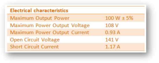
Figure 1.
MA100 (Mitsubishi) [4]. Electrical characteristics.
2.1. MPP Trackers State of the Art
The main characteristic of a PV panel is its I-V curve (current vs. voltage, Figure 2) which is not fixed but varies with temperature and solar irradiance levels. The operation point where the power extracted from the PV panel is maximum (VMPP, IMPP) is called the Maximum Power Point (MPP), and the algorithm to localize the MPP is called the MPPT tracker (MPPT).
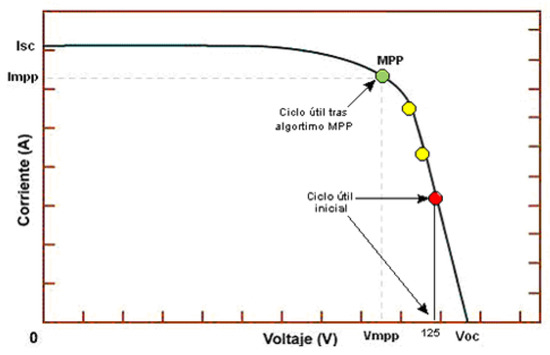
Figure 2.
I-V curve showing the MPP [5].
By connecting directly the battery to the PV panel the PV panel operates at the battery voltage. A DC/DC converter with MPPT is needed as interface to force the PV panel to work as close as possible to the MPP.
The most known MPPTs are the following [6]:
- Perturbe and Observe (P&O): Simple and low cost. Typical accuracies of 80%.
- Incremental conductance: Complex and high cost (high computation devices required). Accuracies over 90%.
- Voltage control/Current control: Very simple and low cost. Accuracies over 70% are reached.
- Voltage/current sweep: Complex, medium cost. Accuracies over 90%.
- Load current/voltage maximization: Simple and low cost. Efficiencies over 90%. Just possible if the load is at constant voltage or constant current.
The last of the options presented here above is selected for this project, since the load is a pure battery and the main goal is to charge the battery with the maximum power.
2.2. DC/DC Converter
A DC/DC buck converter is chosen for this application, due to the fact that no galvanic insulation is needed and the PV panel voltage will be always higher than the battery voltage [7].
3. Project Development
3.1. Power Stage Design
In order to increase the efficiency, a synchronous buck converter is selected (both MOSFETs of the converter acting as switchers are controlled easily by the microcontroller).
The switching frequency of the converter is set to 100 kHz (best compromise between switching losses vs mass and size of the inductor).
The main power elements of the converter are the MOSFETs, the inductance and the output capacitor (M1&M2, L and C on Figure 3).
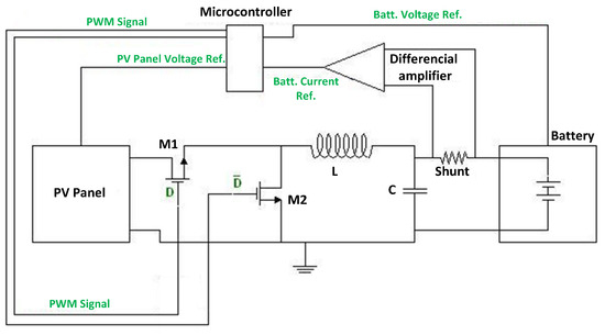
Figure 3.
Scheme of the overall solution.
Power MOSFET selected is IRFP250 from IR. This MOSFET offers good performances under the operation conditions of the converter.
The buck inductor is designed to operate in continuous current mode (CCM) from 100% to 30% of the maximum output power of the converter (above 30 W). According to the maximum output power and the input and output voltages, 288 µH is the value of the inductance needed.
The capacitor value for this application is not a key parameter, since it is in parallel with a battery (which is a huge capacitor).
3.2. Control Stage MPPT
The MPPT is implemented in a low-cost microcontroller [8,9]. In order to save mass and cost, all the possible functions, such as variables sensing, analog to digital conversion and PWM generation are also implemented in the microcontroller. The microcontroller controls, then, both MOSFETs of the converter according to the MPPT and the input/output voltage relationship (Figure 3).
The MPPT algorithm is simple but effective. It regulates the PV panel in the voltage range, starting in a point close to the VOC (Red point, Figure 2). The value of the output current is sensed and stored for comparison. Then, the PV panel voltage is decreased and the output current monitored again. If the output current is higher than the previous step, the PV panel voltage is reduced again for the next step (yellow points, Figure 2). Once the output current is lower than the previous step, the previous step PV panel voltage is the MPP at those conditions (green point, Figure 2). The MPPT will keep this operation point until a significant change on the output power, meaning that the I–V curve of the PV panel, and therefore also the MPP, has changed.
4. Final Results and Conclusions
Simulation results have been compared to test results of a prototype in a test bench with a 12 V battery voltage (Table 1 and Table 2).

Table 1.
Results from simulation with the solution and without the solution (direct connection).
Table 2.
Results from tests with 12V battery.
The proposed solution meets all the objectives proposed. It is a simple and low-cost solution that allows the charge of a battery from a PV panel with high efficiency and high flexibility to work with different battery voltages. Simulation results have been validated by test.
Author Contributions
Á.D.G. has performed the design, the simulations, the assembly of the hardware and the tests. P.S.J.P. has contributed to identify the goals of the application and with the redaction of the paper. N.G.F. has proposed the final solution and supervised the design, the test set-up and the final measurements. X.B.J. has supervised the full project and the redaction of the paper.
Conflicts of Interest
The authors declare no conflict of interest.
References
- EPIA. Global Market Outlook for Photovoltaics until 2016; EPIA: Taipei, Taiwan, 2012. [Google Scholar]
- Solar Power Europe. Global Market Outlook for Solar Power/2016–2020; Solar Power Europe: Brussels, Belgium, 2017. [Google Scholar]
- Photovoltaic Systems Engineering. Roger A. Messenger y Jerry Ventre; CRC Press: Hoboken, NJ, USA, 2010. [Google Scholar]
- Mitsubishi Heavy Industries, Ltd. Mitsubishi MA Series; Mitsubishi Heavy Industries, Ltd.: Tokyo, Japan, 2018. [Google Scholar]
- Image. Available online: http://solar.nmsu.edu/wp_guide/energia.html (accessed on 1 December 2008).
- Zainudin, H.N.; Mekhilef, S. Comparison Study of Maximum Power Point Tracker Techniques for PV Systems. In Proceedings of the 14th International Middle East Power Systems Conference, Cairo, Egypt, 19–21 December 2010. [Google Scholar]
- Fernández, J.A.; García, F.N. Topologías para la Conversión Energética Utilizando Como Fuente Primaria un Panel Fotovoltaico. Pre-. Doctoral Thesis, University of Oviedo, Asturias, Spain, 2006. [Google Scholar]
- Arias, J.; Linera, F.F.; Martin-Ramos, J.; Pernia, A.M.; Cambronero, J. A Modular PV Regulator Based on Microcontroller with Maximum Power Point Tracking. In Proceedings of the 39th IAS Annual Meeting, Blacksburg, VA, USA, 3–7 October 2004. [Google Scholar]
- Du, Y.; Lu, D.D.-C. Battery-integrated boost converter utilizing distributed MPPT configuration for photovoltaic Systems. Sol. Energy 2011, 85, 1992–2002. [Google Scholar] [CrossRef]
Publisher’s Note: MDPI stays neutral with regard to jurisdictional claims in published maps and institutional affiliations. |
© 2018 by the authors. Licensee MDPI, Basel, Switzerland. This article is an open access article distributed under the terms and conditions of the Creative Commons Attribution (CC BY) license (https://creativecommons.org/licenses/by/4.0/).