Abstract
This paper presents a methodological approach for mathematical modelling and physics-based analysis of accessory gearbox (AGB) thermal behavior in gas turbine aero engines. The AGB structure, as one of the main sources of heat in gas turbine aero engines, is firstly described and its power losses will be divided into load-dependent and no-load dependent parts. Different mechanisms of heat generation are then identified and formulated to develop a toolbox for calculation of the churning, sliding friction, and rolling friction losses between contact surfaces of the AGB. The developed tool is also capable of calculating the heat loss mechanisms in different elements of the AGB, such as gears, bearings, and seals. The generated model is used to simulate and analyze the AGB thermal performance in the different flight phases in a typical flight mission, where the obtained results are validated against publicly available data. The analysis of the results confirms the effectiveness of the proposed method to estimate the heat loss values in the AGBs of gas turbine aero engines and to predict the thermal loads of the AGB in different flight phases. The developed tool enables the gas turbine thermal management system designers to deal with the generated heats effectively and in an optimal way.
1. Introduction
Gas turbine engine (GTE) manufactures are facing huge challenges in developing the next generation of GTEs to meet all requirements, due to the increase of fuel price, power and efficiency demands, and limitations and restrictions set by governments and organizations (e.g., the Advisory Council for Aviation Research and Innovation in Europe has a target of a 75% reduction in CO2 emissions and a 90% reduction of NOx emissions by 2050) [1,2]. One of these challenges is to deal with huge thermal loads generated by advanced GTEs components. The engine thermal management system (TMS) should be able to manage these heat loads in an optimal feature to get a safe and reliable operation for the engine. In other words, the main duty of the GTE TMS is to use engine heat sinks (oil, fuel, and air) to manage the thermal loads generated by engine heat sources (gearboxes, bearings, generators, pumps, etc.). There are a few studies in the literature focusing on the thermal management challenges and potential solutions for GTEs. An analytic review on this topic has recently been done by the authors [3], in which the different aspects, current challenges, and potential solutions for the TMS design procedure in new and next generation of GTEs were studied in detail. One of the main challenges in this field is the lack of physics-based models for thermal loads calculation in different TMS components to enable researchers and manufacturers to predict and analyze the thermal loads in each component at different flight phases, based on the geometry, mechanical loads, input and output powers, and other design parameters. This kind of model will enable TMS designers to do a precise sensitive analysis on design and operational parameters, as well as to get a reliable vision about the next generation of TMSs for GTEs [4].
The gearbox is one of the most important elements in gas turbine TMS as a noticeable amount of heat load is generated by this component [5]. So, it is significant to predict its power loss during the design phase to improve the mechanical system design through different perspectives. For instance, reducing gear operating temperature will contribute to better lubrication, less oil degradation, and improving the gear lifetime by improving the resistance to scuffing and micro-pitting [6].
Therefore, this paper will focus on developing a physics-based tool to calculate the thermal load generated by different elements of the accessory gearbox (AGB) in gas turbine aero engines.
2. Accessory Gearbox Heat Loss Mechanisms
The accessory gearbox drives the accessories of the engine like generator, fuel and oil pumps, hydraulic pumps, etc. So, it is an essential element for the operation of the engine or the aircraft on which it is mounted. The power loss mechanisms inside gearbox can be separated into two groups: no-load dependent losses and load-dependent losses. No-load dependent losses include churning losses caused by gears, seals, and bearings, and load-dependent losses are frictional losses caused by gears and bearings [7].
No-load dependent losses mainly consist of Windage and churning power losses, the churning losses are one of the main power losses especially at high oil fill level and rotational speeds [8]. This type of power loss occurs between gears even without torque transmission in the rotation of mechanical components and it is related to the density, viscosity, and immersion depth of the components on a sump lubricated gearbox, and it also depends on the internal design of gearbox casing and operating conditions. No-load losses of rolling bearings mainly depend on the size, type, and bearing arrangement, immersion depth, and lubricant viscosity [9].
Load-dependent power losses occur because of contacts between the gears’ teeth during power transmitting, which are mainly depends on friction coefficient, transmitted power, and sliding velocity in the contact area between teeth [9].
The dependence of no-load losses on the lubricant viscosity and the frictional losses is influenced by the oil characteristics and the ability to provide low friction coefficient and lubricant film. This is important to increase gearbox efficiency and to enhance gears and bearings life [10].
Most studies have focused on power loss, and gear efficiency is related to the planetary gear system, power gearbox (PGB). Some of these studies have focused on spin power losses, but most of the studies have investigated mechanical losses. These studies provide a significant database for predicting power loss in gears, but it considers only a single gear pair. The review of these studies discloses the need for a model can predict the power loss in the AGB for typical aero-engine.
The accessory gearbox consists of sets of spur gears connected to each other, each gear drives one element, such as the generator, or pump. The power losses can be divided into load-dependent and no-load dependent according to their mechanical component and their relation to transmitted torque that generates them [3]. In this way, the total power loss (PL) can be subdivided into no-load and load dependent related to gears ( + ), bearings ( + ), and no-load dependent for seals ().
The total power losses in the accessory gearbox are the sum of all sources of losses in each contact pairs and single elements inside generated by load and no-load losses equal to the heat evacuation from AGB to the environment [9].
The share of power losses between different sources strongly depends on the gearbox design configuration.
3. Mathematical Modelling of Heat Losses
The physics-based model for heat loss calculation is described in this section.
3.1. No-Load Dependent Losses
Depending on the input speed and power, gearbox design and lubricant characteristics, the no-load dependent losses are a very important source of heat dissipation within an accessory gearbox. Due to the complicated design of the AGB, it is not straightforward to generate a model that consists of a general formulation to assess this mechanism of power loss. The main objective of this study is to accurately predict the power losses considering friction torque loss in the meshing gears.
3.1.1. Gears Churning Loss
In recent decades, many studies have investigated the influence of the energy loss mechanism and parameters on power loss in the gearbox. Boness (1989) [10] investigated the influence of diameter and oil fill level on a disk and drove an empirical formulation through experiments. Terekhov (1975) [11] studied single meshing gears rotating immersed in a fluid and developed an empirical equation using a dimensionless moment coefficient from several experiments. Höhn et al. [12] developed an empirical formation through experimental work, and concluded that reducing oil level can reduce the churning loss but not the gear temperature. Gear churning losses is the main source of power loss for splash lubricated gears, which is generated by rotating gears totally or partly immersed in fluid lubrication. Changenet et al. [13] developed a mathematical model for calculating the gear churning loss based on the series of experimental tests, and carried out a comprehensive dimensional analysis to tune the model. In this paper, this model is selected, since it overcomes some of the limitations of the previous research in gear churning losses from accuracy, validity range, and reliability points of view. The model proposed by Changenet et al. [13] depends on the regime of the flow and Reynolds number that defines the laminar-turbulent transition determined by experimental results. It is very difficult to determine the transition of the laminar-turbulent regime inside an oil sump, due to the infinite combination parameters and design features [14].
Gear churning power loss is mainly responsible for no-load dependent losses and depends on rotational speed, immersion area and depth, gear geometry, lubricant density, and viscosity, as shown in Equation (2):
where is the lubricant density, is the rotational speed in rad/s, is immersion surface area, is the pitch radius, and the expression has been determined depending on the flow regime:
For
For
where is the immersion depth, is the gear pitch diameter, is the oil volume, is the lubricant kinematic viscosity, is the tooth face width, Froude number, depending on gear parameters , Reynolds number .
It should be mentioned that this formulation and corresponding flow regimes are valid for the steady-state operating condition.
3.1.2. Bearings Churning Loss
The bearing churning losses are mainly depending on the bearing geometry and type, speed and lubricant viscosity.
where is bearing coefficients of loss, is the dynamic viscosity, is the rotation speed, and is the mean diameter.
3.1.3. Seals Churning Loss
The seal churning losses are mainly occurring between seal tip and shaft in the contact zone. However, many studies have been investigated on seals losses but this phenomenon still not well understood, due to small of the contact zone and difficult to parametrize. With regard to [15,16], the seal losses mainly depend on seal diameter and shaft speed. Equation (5) is used to predict the seal losses, but this formula does not consider the oil viscosity:
where is the shaft diameter.
3.2. Load Dependent Losses
Load dependent losses include gear mesh loss and power loss in bearings that could be calculated as follows:
3.2.1. Power Loss in Meshing Gears
Generally, the power loss due to gear mesh is determined by the normal load, relative rolling and sliding between lubricated meshing gears. Friction interaction between meshing gears must be considered as it is influenced by all characterized elements. The main contributors to power loss are the friction coefficient and load distribution along the line of contact of meshing gear [3]. This study will consider the friction coefficient and load distribution constant along the line of contact. Ohlendorf [17], has introduced the equation to calculate the load-dependent for spur gears.
where : mean friction coefficient along the path of the contact [18], : is the gear loss factor. : is the power input.
3.2.2. Power Loss in Bearings
According to Wimmer et al. [16], the bearings load dependent loss mainly depends on the load applied, mean diameter, and friction coefficient of the bearings:
where is the radial and axial load applied, is the bearings friction coefficient, is the mean diameter.
Finally, by adding the values of Equations (2), (5)–(8) and putting them in Equation (1), the total heat loss in the accessory gearbox will be calculated.
4. Results Analysis
The equations described in previous sections have been used to generate a simulation toolbox in MATLAB environment to calculate different power loss mechanisms in different elements of accessory gearbox for gas turbine engines. The toolbox is able to predict the heat load values in the AGB, due to friction and churning losses in gears and bearing and seals for each element.
It should be mentioned that in this study, the simulation model includes only the elements that have huge impacts on the total power losses while ignoring other elements (e.g., de-oiler). The schematic of accessory gearbox gear set configuration for an aero-engine is shown in Figure 1, it mainly consists of a set of spur gears connected to drive each element at different speed ratios and power, a ball bearing, and gear shaft, seals, a gearbox housing. According to [19], the typical speed of each element in the accessory gearbox at maximum power output, such as fuel pump, generator, and oil pump, are listed in Table 1.
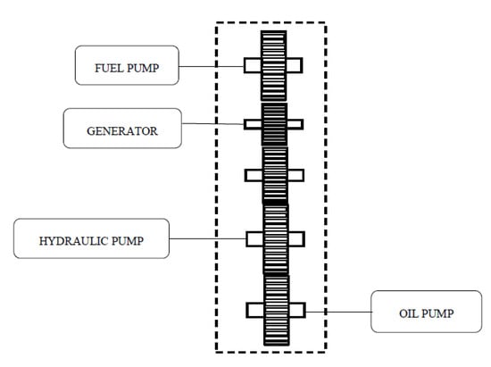
Figure 1.
Schematic of accessory gearbox (AGB) gear set configuration.

Table 1.
Accessory gearbox drives speeds.
In this study, the power loss model of the accessory gearbox is simulated through operating in a different flight phase, wide range of operating conditions, with an input power and speed varied for each flight condition, according to engine manufacturer, the speed and power input data in the accessory gearbox are taken from real engine of CFM56 family through different flight phases. The first row of the Table 2 presents the core engine power. A percentage of this power will be transmitted to the AGB at different flight phases. With regard to Rolls-Royce [20] and Pratt & Whitney [21], the AGB drives the accessories, fuel pumps, oil pumps, generators etc., by handling between 400–500 hp. The second raw presents the percentage of high-pressure rotational speed (from [19]), which is used as the input for the AGB physics-based model.
Table 2.
Accessory gearbox speed and engine core power during flight phases.
The simplified model of AGB internal structure of gears is shown in Figure 1. Reference [22] provides basic design parameters of the spur gear, which are also listed in Table 3.
Table 3.
Design parameters of AGB.
Figure 2 shows the power loss toolbox generated with the graphical user interface (GUI) in MATLAB (R2019a) to enable the user to analyze different heat load mechanisms in different AGB elements separately and/or in total.
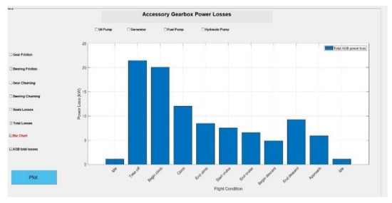
Figure 2.
Accessory gearbox heat load calculation toolbox.
By applying the flight phases of Table 2 to the model generated in MATLAB, the results of the heat load in different elements of the AGB according to different heat loss mechanisms are generated, and will be analyzed here.
Figure 3 shows the friction loss in all AGB elements, where the gear connected to the generator has the highest friction loss in take-off condition compared to other elements, which mainly depends on the friction coefficient and the load applied to the meshing gears.
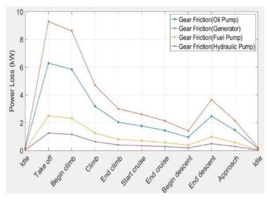
Figure 3.
Power losses due to gear friction.
Figure 4 confirms that the bearings friction losses are influenced directly by the applied load and speed. This figure is also showing a direct relation between the power loss value and the increase of speed and power transmitted.
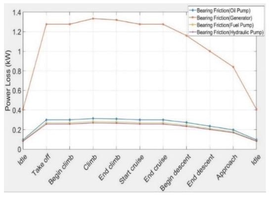
Figure 4.
Power losses due to bearing friction.
Figure 5 and Figure 6 show the losses due to gear and bearing churning in all AGB components, respectively. Regarding Section 3, the fluid viscosity and density index influence the churning losses where the oil properties change with oil temperature and operating conditions.
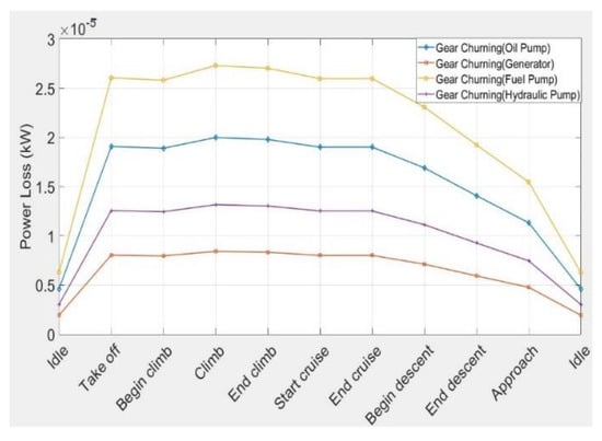
Figure 5.
Power losses due to gear churning.
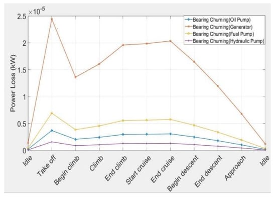
Figure 6.
Power losses due to bearing churning.
The fuel pump has a high loss compared to the generator due to the influence of gear diameter. It can be seen that the impact of the oil temperature on the churning power losses is mainly reflected in the density and dynamic viscosity of the oil. The churning losses at take-off condition seem to have a high value on all AGB components, due to change the viscosity of the oil. Additionally, the oil fill level influences the churning power loss, the losses increase with increasing the immersion level of the gear teeth.
Finally, Figure 7 shows the power loss produced by shaft seals which is considered as no-load dependent loss, and less important in the total losses. It can be seen that the seals losses varied with speed through all flight conditions. The results presented in Figure 3, Figure 4, Figure 5, Figure 6 and Figure 7 confirms that the majority of the heat load in accessory gearbox is generated by gear and bearing friction mechanisms.
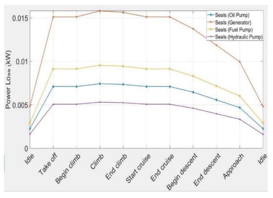
Figure 7.
Power losses due to seals friction.
By adding the values of different heat loss mechanisms, Figure 8 shows the total power loss predicted in accessory gearbox components. It can be seen that:
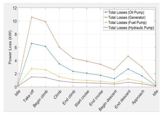
Figure 8.
Total power loss for each element in AGB.
- The gear set connected to the generator creates the highest value of loss in comparison with other elements due to the high power transmitted which causes high friction between the gears as the friction coefficient change with power transmitted.
- The oil and fuel pump gear sets have the next ranks in generating heat loads. The loss in hydraulic pump is less than 2 kW in all flight phases.
- The assumption of neglecting other elements (e.g., de-oiler and heat transfer from the engine components) is valid, as the generated heat loads would be very small (in the order of 1 kW and less).
By adding all values in Figure 8, Figure 9 shows the overall power loss occurs in accessory gearbox through all flight conditions. The model presented in this work seems to perform quite well in overall power loss prediction in AGB, given the proper geometry and operating conditions. The overall losses followed the trend of the friction losses because of the high heat generated between the friction surfaces compared to the heat produced by the gears and bearing digging in the oil.
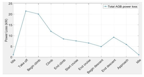
Figure 9.
Overall power loss in AGB.
A comparison of the results with the value reported in [23] shows that the total accessory gearbox power loss is quite close to the experimental value reported by manufacturers. In [23], the total heat load generated by the AGB for an 18 klbs engine at take-off condition is 17 kW. The case study of this paper is a CFM56-5 like with the thrust value of 25 klbs and the heat load calculated by the generated tool is 21.6 kW. The linear relationship works very well between these two values. However, more case studies and analyses are required to confirm and enhance the reliability and validity of the generated tool.
5. Conclusions
A MATLAB tool for predicting different heat loss mechanisms, as well as heat load values in accessory gearbox components of gas turbine aero engines, was developed based on the physics-based modelling approach. The tool is capable of calculating load-dependent and no-load dependent heat losses in AGB structure including churning loss in gears, bearings, and seals, as well as gear mesh loss and bearing friction loss at different flight phases. The heat losses could also be calculated in different gear sets in the AGB, including gear sets connected to the generator, oil pump, fuel pump, and hydraulic pump. The results of the simulation of a complete mission for a CFM56-5 AGB show that the friction losses in gears and bearing generate the majority of the heat load in the AGB. Moreover, between different elements of the AGB, the gear set connected to the generator creates the highest amount of heat loss in comparison with other elements. The heat load value is maximum at the take-off condition due to the high transmitted power and the highest rotational speed. This value for the case study is 21.6 kW, which is in good agreement with the reported experimental data in the literature. The tool could be used for thermal management system designers for different gas turbine aero-engines and different missions, because all design parameters (geometry, oil characteristics, load, and rotational speed) are considered in a physics-based feature in the tool, and could be tuned for other applications.
Author Contributions
Conceptualization, S.J.; Data curation, A.B.; Formal analysis, A.B.; Investigation, A.B.; Methodology, A.B.; Project administration, S.J.; Resources, T.N.; Software, A.B.; Supervision, T.N.; Writing—original draft, S.J.; Writing—review & editing, T.N. and S.J. All authors have read and agreed to the published version of the manuscript.
Funding
This research received no external funding.
Conflicts of Interest
The authors declare no conflict of interest.
References
- Directorate-General for Research and Innovation; Directorate-General for Mobility and Transport. Flightpath 2050, Europe’s Vision for Aviation Maintaining Global Leadership & Serving Society’s Needs; Report of the High-Level Group on Aviation Research; Publication office of the EU: Brussels, Belgium, 2011. [Google Scholar]
- Jafari, S.; Nikolaidis, T. Turbojet engine industrial min-max controller performance improvement using fuzzy norms. Electronics 2018, 7, 314. [Google Scholar] [CrossRef]
- Jafari, S.; Nikolaidis, T. Thermal management systems for civil aircraft engines: Review, challenges and exploring the future. Appl. Sci. 2018, 8, 2044. [Google Scholar] [CrossRef]
- Rolls Royce Deutschland Ltd. & Co KG. Heat Exchange System for A Power Gearbox, A Power Gearbox and A Turbo Engine with A Power Gear Box. Patent No. EP3244039 A1, 22 June 2017.
- Nutakor, C.; Kłodowski, A.; Sopanen, J.; Mikkola, A.; Pedrero, J.I. Planetary gear sets power loss modeling: Application to wind turbines. Tribol. Int. 2017, 105, 42–54. [Google Scholar] [CrossRef]
- Magalhães, L.; Martins, R.; Locateli, C.; Seabra, J. Influence of tooth profile and oil formulation on gear power loss. Tribol. Int. 2010, 43, 1861–1871. [Google Scholar] [CrossRef]
- Martins, R.C.; Cardoso, N.F.R.; Bock, H.; Igartua, A.; Seabra, J.H.O. Power loss performance of high pressure nitrided steel gears. Tribol. Int. 2009, 42, 1807–1815. [Google Scholar] [CrossRef]
- Hu, X.; Jiang, Y.; Luo, C.; Feng, L.; Dai, Y. Churning power losses of a gearbox with spiral bevel geared transmission. Tribol. Int. 2019, 129, 398–406. [Google Scholar] [CrossRef]
- Fernandes, C.M.; Marques, P.M.; Martins, R.C.; Seabra, J.H. Gearbox power loss. Part I: Losses in rolling bearings. Tribol. Int. 2015, 88, 298–308. [Google Scholar] [CrossRef]
- Boness, R.J. Churning Losses of Discs and Gears Running Partially Submerged in Oil. In Proceedings of the ASME International Power Transmission and Gearing Conference, Chicago, IL, USA, 7–9 April 1989; Volume 1, pp. 355–359. [Google Scholar]
- Terekhov, A.S. Hydraulic losses in gearboxes with oil immersion. Russ. Eng. J. 1975, 55, 7–11. [Google Scholar]
- Höhn, B.R.; Michaelis, K.; Vollmer, T. Thermal Rating of Gear Drives: Balance between Power Loss and Heat Dissipation; American Gear Manufacturers Association: Alexandria, VA, USA, 1996. [Google Scholar]
- Changenet, C.; Leprince, G.; Ville, F.; Velex, P. A note on flow regimes and churning loss modeling. J. Mech. Des. 2011, 133, 121009. [Google Scholar] [CrossRef]
- Fernandes, C.M.; Martins, R.C.; Seabra, J.H. Torque loss of type C40 FZG gears lubricated with wind turbine gear oils. Tribol. Int. 2014, 70, 83–93. [Google Scholar] [CrossRef]
- Concli, F. Low-loss gears precision planetary gearboxes: Reduction of the load dependent power losses and efficiency estimation through a hybrid analytical-numerical optimization tool. Forschung im Ingenieurwesen 2017, 81, 395–407. [Google Scholar] [CrossRef]
- Wimmer, J.A. Lastverluste von Stirnradverzahnungen: Konstruktive Einflüsse, Wirkungsgradmaximierung, Tribologie. Doctoral Dissertation, Technische Universität München, München, Germany, 2006. [Google Scholar]
- Ohlendorf, H. Verlustleistung und Erwärmung von Stirnrädern. Doctoral Dissertation, Technische Universität München, München, Germany, 1958. [Google Scholar]
- Fernandes, C.M.; Marques, P.M.; Martins, R.C.; Seabra, J.H. Gearbox power loss. Part III: Application to a parallel axis and a planetary gearbox. Tribol. Int. 2015, 88, 317–326. [Google Scholar] [CrossRef]
- Feehally, T. Electro-Mechanical Interaction in Gas Turbine-Generator Systems for More-Electric Aircraft. Doctoral Dissertation, The University of Manchester, Manchester, UK, 2012. [Google Scholar]
- The Jet Engine; 7 Accessory drives; Rolls-Royce: Birmingham, UK, 1986; pp. 65–71. ISBN 0-902121-04-9.
- The Aircraft Gas Turbine Engine and Its Operation, Part No. PWA 182408 PWA Oper. Instr. 200, Installation Engineering; Pratt & Whitney: East Hartford, CT, USA, 1988; pp. 3-45–3-47.
- Niemann, G.; Winter, H. Maschinenelemente. II: Getriebe allgemein, Zahnradgetriebe-Grundlagen, Stirnradgetriebe; Springer: Berlin/Heidelberg, Germany, 2003. [Google Scholar]
- Streifinger, H. Fuel/oil system thermal management in aircraft turbine engines. In Proceedings of the RTO Meeting Proceedings, Symposium, Design Principles and Methods for Aircraft Gas Turbine Engines, Toulouse, France, 11–12 July 1998; pp. 12–24. [Google Scholar]
© 2020 by the authors. Licensee MDPI, Basel, Switzerland. This article is an open access article distributed under the terms and conditions of the Creative Commons Attribution (CC BY-NC-ND) license (http://creativecommons.org/licenses/by-nc-nd/4.0/).