Abstract
This paper presents the first-of-its-kind full-crown Detached Eddy Simulation (DES) of a radial turbine designed for operation in a transcritical CO2-based power cycle. The simulation domain contains not only the main blade passage but also the exhaust diffuser and the rotor disk cavities. To ensure accurate simulation of the turbine, two hybrid RANS/LES models, using the Improved Delayed Detached Eddy Simulation (IDDES) approach, are validated in a flow around a circular cylinder at , obtaining excellent agreement with other experimental and numerical studies. The turbine simulation was performed using the k--SST-based IDDES model, which was identified as the most appropriate approach for accurately capturing all relevant flow dynamics. Thermophysical properties of CO2 are modeled with the Span–Wagner reference equation, which was evaluated by a highly efficient spline-based table look-up method. A preliminary assessment of the grid quality in the context of DES is performed for the full-crown simulation, and characteristic flow features of the main passage and cavity flow are highlighted and discussed.
1. Introduction
From a technological and economical point of view, trans- and supercritical CO2-based power cycles represent a promising future energy systems technology [], albeit a challenging one from the design perspective, as the flow of supercritical CO2 (sCO2) in turbomachinery blading, sealing, etc., is governed by non-ideal thermodynamics []. For shaft power outputs of around 10 , radial turbines with a high stage load are preferred for sCO2 applications []. High stage load leads to high torque, which needs to be transmitted by a shaft with an appropriate diameter. This requires sealing at large radii, leading to high leakage flows. For a highly effective seal design, which is crucial to avoid excessive parasitic and windage losses in operation, accurate thermodynamic modeling is necessary. Additionally, the high expansion ratios over the impeller cause high thrust loads, which have to be balanced by the thrust bearings.
As technological developments for sCO2 turbomachines in the middle–high power output range are still in their (late) infancy, especially as far as experiments are concerned, there is a limited amount of research on sCO2 turbines that are actually in operation []. From the perspective of numerical analysis, full-crown, scale-resolving simulations represent a promising method for analyzing issues related to seals and thrust load and could deepen our current understanding of flow features in sCO2 turbines. Flow field data from this kind of simulation can be used to investigate sealing effectiveness, thrust load (by integrating the pressure distribution over the wheel surface), or windage loss to assess whether common meanline design strategies are also applicable at non-ideal thermodynamic states [].
In an industrial context, it would be desirable to be able to carry out a time-accurate numerical simulation of an entire machine, with all of its components, in order to fully capture the interactions between different parts of the system. The use of wall-resolved Large Eddy Simulation (LES) for high-Re turbine flows is typically restricted to a limited number of passages without endwalls due to the high computational effort required to resolve the spatial and temporal scales in near-wall regions (see [,]). Lately, wall-modeled LES (WMLES), a technique that aims to limit computational costs by modeling the near-wall regions in LES computations, has been proven to be quite effective (see [,]). However, the industrial standard for the numerical simulation of turbomachinery flows is still Reynolds-Averaged Navier–Stokes (RANS) simulation.
For research purposes, however, hybrid RANS/LES models represent a reasonable compromise between the desired degree of accuracy and the need for moderate computational effort. Today, highly popular hybrid RANS/LES methods include the Scale-Adaptive Simulation (SAS) proposed by Menter’s group [] and the Detached Eddy Simulation (DES) developed by Spalart []. DES combines the RANS method in the near-wall region with Smagorinsky-like LES in separated areas by assessing the ratio of turbulent dissipation length scales and local grid density, while the SAS relies on an additional sink term in the RANS equations to dampen the production of turbulent viscosity, thereby allowing for more unsteady fluctuations in the flow field. SAS requires relatively strong flow instabilities in order to switch to scale-resolving mode. Whereas in DES, there is an explicit switch between RANS and LES model formulations based on the local grid spacing and turbulent length scale. More carefully crafted grids are necessary to avoid unwanted activation of the LES modality. For the current study, we decided to proceed with the DES approach, whose superior performance over SAS was also demonstrated in []. To avoid the well-known pitfalls of the original DES formulation, i.e., modeled stress depletion leading to grid-induced (artificial) separation, the most recent version of the model, called Improved Delayed Detached Eddy Simulation (IDDES), is implemented in the in-house Computational Fluid Dynamics framework named Structured High-order Aerothermochemistry Real Fluid Computations (acronym: SharC) [,,].
The implementation of the IDDES model is validated for both Spalart–Allmaras and k--SST-based models, hereinafter referred to as SA-IDDES and SST-IDDES, by investigating the flow over a circular cylinder at a Reynolds number of 3900 (, where is the free-stream velocity, D is the diameter of the cylinder, and is the kinematic viscosity). In the following, we use the subscript ∞ to denote free-stream quantities. At this Reynolds number, the flow is in the subcritical regime, in which transition to turbulence takes place in the detached shear layers. Despite the simple geometry, the flow exhibits a range of complex phenomena, including boundary layer separation, recirculation, shear layer instabilities, and the formation of large three-dimensional vortical structures in the wake structure and is therefore a widely recognized benchmark for turbulence research and turbulence model validation.
To the authors’ best knowledge, there is no numerical study on an sCO2 radial turbine available that not only uses a hybrid RANS/LES approach in order to resolve the turbulent nature of the flow at all relevant scales but also applies a state-of-the-art reference equation of state for CO2. Recently, Keep et al. [] investigated low-specific speed turbine designs by performing k--SST-based RANS simulations of a single passage and full-crown URANS to breakdown the relative importance of loss mechanisms. Zhou et al. [] studied the sensitivity of a radial inflow turbine to tip leakage flows and therefore tip clearance losses using RANS calculations. The influence of evolving coherent turbulent structures within secondary flows and wake structures on the flow field in sCO2 turbines has not been considered in any of the aforementioned studies. For turbomachines operated in air, i.e., under ideal gas conditions, there are a few numerical studies available using DES. Im et al. [] conducted full-crown DES of a transsonic compressor rotor and found that DES predicts rotating stall inception more realistically than URANS. Based on this work, the same authors performed similar investigations by analyzing the flow in a whole compressor stage [].
This paper presents the first full-crown Detached Eddy Simulation (DES) of a radial turbine designed by Everllence SE for operation in supercritical CO2-based thermal energy storage systems. These systems require the turbine to operate under high expansion ratios and low volumetric flow conditions. To minimize leakage flows across the stage at supercritical inlet pressures—corresponding to high mass densities—a covered, low-specific-speed rotor design was chosen. The present study investigates not only the flow within the bladed sections but also the exhaust diffuser and the rotor disk cavities.
The rest of this paper is organized as follows: In Section 2, the numerical framework, including the governing equations, the thermodynamic and turbulence models, as solved in the present DES study, is described. Then, in Section 3, an initial validation study of the newly implemented IDDES approach considering subcritical flow past a circular cylinder is presented. Finally in Section 4, the results of a large-scale IDDES of a recently developed radial turbine stage are discussed, focusing on the flow in the rotor cavities and the seals they contain.
2. Mathematical Model and Solution Method
In this section, the governing equations solved in the in-house flow solver SharC [,] are presented. The set of equations is closed by a tabulated multiparameter equation of state (EoS) to model the thermodynamic behavior of CO2. Turbulent stresses and heat fluxes are modeled according to the Boussinesq hypothesis. We employ both the Spalart–Allmaras (SA) [] and k--SST(SST) model [], where hybrid RANS/LES modeling is achieved using the DES approach []. We briefly introduce spatial discretization while focusing on the hybrid formulation of the advective flux. Both the cylinder and turbine flow simulations rely on a similar spatial discretization but use different temporal discretization schemes. Therefore, the latter are introduced in the computational setup in the respective sections.
2.1. Governing Equations
The present work considers the three-dimensional Navier–Stokes equations in conservative form:
formulated in a non-inertial frame of reference, which steadily rotates with an angular velocity around a fixed axis. The vector U represents the conserved variables , comprising density , specific momentum , and specific total energy density , relative to the rotating frame of reference. The latter is related to the specific static internal energy e as , where is the entrainment velocity and is the distance vector to the axis of rotation. The advective flux is given as
where p represents thermodynamic pressure, is the identity matrix (), and is the relative stagnation enthalpy (rothalpy). The diffusive flux is given as
where is the viscous stress tensor according to Stokes’ hypothesis and is the heat flux vector following Fourier’s law. The formulation of the governing equations in a non-inertial system leads to the occurrence of inertial forces
where is the contribution from the Coriolis force and is the contribution from the centrifugal force.
2.2. Thermodynamic Model
The primitive (sometimes referred to as physical) variables are calculated by the state-of-the-art reference EoS by Span and Wagner [] (hereafter referred to as the ) from the vector of conserved variables U. Since the evaluation of the multiparameter EoS can easily become a performance bottleneck in the context of scale-resolving simulations [], a spline-based table look-up method (SBTL) is used. The SBTL method employs biquadratic polynomial spline interpolation, addressing key shortcomings of traditional local interpolation techniques like bilinear or bicubic schemes. Unlike bilinear interpolation, spline functions offer continuous first derivatives. Additionally, biquadratic spline polynomials can be analytically inverted with respect to their independent variables, enabling fast and numerically stable backward evaluations—unlike bicubic interpolation, which requires computationally intensive inverse functions involving trigonometric evaluations. The spline functions are built on piecewise equidistant nodes in transformed variables, facilitating linearization and allowing for the use of simple search algorithms. Thermodynamic property grid points for CO2 are computed using the , along with molecular viscosity and thermal conductivity correlations from Laesecke et al. [] and Huber et al. [], respectively. For tabulation, specific volume v and specific internal energy e are selected as the independent thermodynamic variables, as they can be directly obtained from conservative variables by
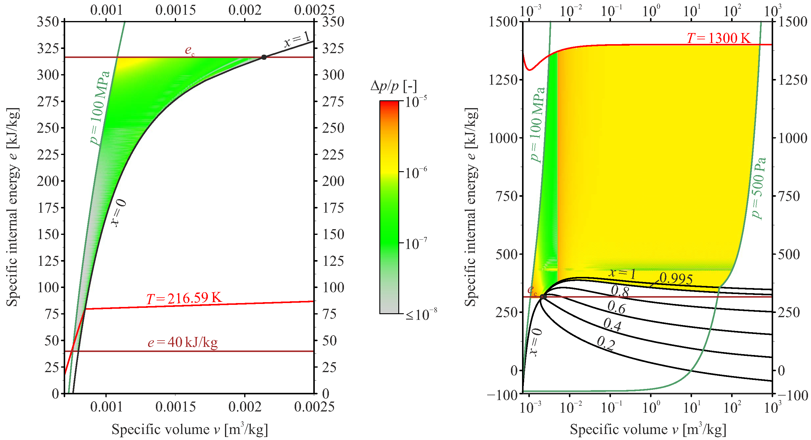
The SBTL property library is valid for temperatures ranging from 216.59 K to 1300 K and pressures between 0.5 kPa and 100 MPa. The permissible deviations of the SBTL functions from the are listed in Table 1. As an illustration, Figure 1 shows the relative deviations in pressure compared to direct evaluation of the . These deviations are consistently below the specified thresholds. Except near the critical point, where isobaric heat capacity and thermal conductivity diverge, the deviations remain smaller than the uncertainties inherent to the and the associated transport property correlations. For a detailed discussion of the method and its development, interested readers are referred to []. The library had already been applied in the numerical investigation of an sCO2-compressor [], where it demonstrated its superior performance compared to the direct evaluation of the via the REFPROP-API. Karaefe et al. [] have shown that the SBTL is able to reduce the computational overhead caused by the significantly from 4000% to only 30% compared to a baseline ideal gas simulation.
Table 1.
Permissible deviations for development of spline functions from [] as well as correlations for molecular viscosity [] and thermal conductivity [].
Figure 1.
Relative deviations of spline functions for from underlying in the liquid and gas regions.
For the validation study considering the flow past a circular cylinder, we assume calorically and thermally perfect gas behavior, i.e., , where is the ratio of specific heats, and with specific gas constant . Molecular viscosity is constant and thermal conductivity is calculated assuming a constant Prandtl number of 0.71.
2.3. Turbulence Model
For brevity, we will limit the introduction of the DES approach to the presentation of Spalart’s original idea [] and highlight the key differences when applied to the SST model. Finally we will introduce the hybrid (blended) RANS/LES length scale for the Improved Delayed Detached Eddy Simulation (IDDES) approach proposed by Shur et al. [].
Detached Eddy Simulation, as originally developed by Spalart [], is a non-zonal hybrid RANS/LES approach, in which the entire boundary layer, or attached region, is treated using an RANS model and Smagorinsky-like LES closure is applied to separated (detached) regions. In the original formulation of DES, the switch between both models is purely based on a length scale controlling the destruction of eddy viscosity in the SA model, defined as
where d is the wall distance, is a model constant of order one, and is a measure of grid density.
Travin et al. applied the DES approach to the two-equation SST model in order to improve the prediction of flow separation over the SA model []. In contrast to the SA model, which uses wall distance, the SST model has an internal length scale based on its primitive variables , where k is the turbulent kinetic energy and is the specific rate of dissipation. This brings us to a more general definition of Equation (6):
where , and for the SST model, . In addition, the constant needs to be evaluated based on Menter’s blending functions. The only term affected by modification of the length scale is the dissipation term in the transport equation for the turbulent kinetic energy.
In the original definition of DES, the hybrid length scale depends purely on the local grid size, which leads to problems in regions of intermediate grid spacing where the model should transition from RANS to LES. The so-called modeled stress depletion refers to an unintended reduction in eddy viscosity, which can ultimately lead to an artificial (grid-induced) separation. To avoid this unintended behavior, Spalart et al. introduced a shielding function in the definition of the hybrid length scale []. Values of this function close to 0 indicate an LES region, while higher values indicate an RANS region. Thanks to this modification, the model no longer purely depends on the wall distance (or other RANS length scales) but also on the local eddy viscosity, which delays the switch. Shur et al. extended this so-called Delayed Detached Eddy Simulation (DDES) approach to wall-modeled LES capabilities by remedying log-layer mismatch with an additional function and introducing empirical blending in order to provide a rapid switch from RANS to LES mode near the wall in WMLES []. Furthermore, Gritskevic et al. recalibrated the modeling constants for the SST-based IDDES model []. The final definition of the hybrid length scales includes a blending function , which is designed to activate either the DDES or WMLES branch of the IDDES model, yielding
Provided that the mesh resolution is sufficiently high and the RANS model is only active in the boundary layer, the use of the IDDES model can be understood as an application of the WMLES strategy [].
2.4. Spatial Discretization
Spatial discretization is carried out on structured grids using the finite-volume method, according to a cell-centered scheme. The Monotone Upstream-Centered Schemes for Conservation Laws (MUSCL) approach is applied to replace a piecewise-constant reconstruction with a first-order linear approximation of the flow variables at the cell interface, thereby achieving second-order spatial accuracy. To prevent non-physical oscillations near steep gradients in the flow solution, the MUSCL reconstruction is enhanced by employing the van Albada slope limiter [].
The advective (numerical) fluxes are calculated using a blending approach, as shown in Equation (9), between the upwind-biased scheme (subscript upw) AUSM+-up [] and central differences (subscript ctr).
The hybrid advection scheme aims to find a balance between the minimization of numerical dissipation, typically achieved using central schemes, and the control of potential instabilities. This is particularly important in the LES region of the DES, where central schemes help capture small-scale turbulence by reducing dissipation but may introduce instabilities, which are controlled by the upwind-biased component of the scheme. The empirical flux blending factor, , is defined according to [,], with the goal of achieving an “almost upwind” scheme in the RANS region () and an “almost central” scheme in the LES one. The blending factor is also designed to favor the upwind scheme in irrotational flow regions to ensure stability in areas where meshes are typically coarser.
3. IDDES Model Validation
Cylinder flow at a Reynolds number of 3900 has been extensively studied both experimentally and numerically and is a widely recognized benchmark for turbulence research and for validating turbulence models []. Despite the simple flow configuration, due to the circular shape, the precise location of flow separation cannot be predicted in advance and is influenced by the flow regime or upstream conditions. As a result, numerical predictions of turbulence statistics in the near-wake region are highly sensitive to the turbulence treatment, potentially leading to significant discrepancies depending on the modeling approach and resolution used [].
The first Particle Image Velocimetry (PIV) measurements in the very-near-wake region were presented in [], followed by measurements in a further downstream region with Hot Wire Anemometry in []. More detailed PIV measurements in the very-near-wake region were presented later in []. A wide range of numerical simulations have been carried out using Direct Numerical Simulation (DNS) [], LES [,,,,], DES [], and further hybrid RANS/LES models [].
3.1. Computational Setup
The computational domain for the canonical cylinder test case, with its dimensions, and the reference system are shown in Figure 2. The grid is a multi-block O-grid, where the size of the smallest cells on the cylinder wall is calculated so that is of the order of one. The total number of cells is approx. . As in [], where this case was investigated with a high-order compressible solver, the Mach number is specified to be and an isothermal boundary condition is used for the cylinder wall, setting the temperature equal to the free-stream value . The domain is periodic in the spanwise direction, while symmetry conditions are applied to the top and bottom boundaries. A Riemann boundary condition, prescribing uniform stagnation pressure, stagnation temperature, and flow angles, is used at the inlet, while a non-reflecting boundary condition [] is applied at the outlet to facilitate the convection of the von Kármán vortex street. Time integration is performed with an explicit four-stage Runge–Kutta method using a fixed time step, , resulting in a CFL number that is always <0.7 to ensure stability as well as appropriate time resolution. The initialization period is set to ten flow-through times , in accordance with the criterion that the turbulent wake is considered fully developed after approximately , as reported by Parnaudeau et al. []. The results presented have been averaged over a period corresponding to . The normalized averaging time is ≈760 exceeds reference data published in the literature []. Statistics are not only averaged over time but also spatially averaged in the periodic spanwise direction. In the rest of the paper, the averaging operator is denoted by .
Figure 2.
Setup for cylinder flow.
3.2. Instantaneous Flow Field
A snapshot of the spanwise component of the vorticity is presented in Figure 3. The alternating separation of the boundary layer results in a time-dependent recirculation region downstream of the cylinder (in the considered subcritical regime, the boundary layer remains laminar, even directly after separation). The primary vortex zone is formed from the Kelvin–Helmholtz instability, generated in the two shear layers at the edges of the separated flow. Smaller vortices accumulate forming a large-scale structure behind the cylinder and decay as the flow moves downstream of the cylinder. Continuous vortex shedding leads to the formation of the characteristic von Kármán vortex street, which can be observed in Figure 3.
Figure 3.
Spanwise component, , of instantaneous vorticity for SST-IDDES.
3.3. First- and Second-Order Statistics
Figure 4a shows the shielding function, , for the SST-IDDES case. As expected for all variations of the DES approach, a thin RANS layer is observed near the cylinder wall. However, consistent with the specific characteristics of IDDES, the RANS region is wider than in standard DES, which helps prevent a premature switch to LES. Additionally, in the flow separation region behind the cylinder, a clear distinction between the RANS and LES regions is visible, effectively reducing the so-called “grey area” [].
Figure 4.
SST-IDDES model assessment for validation study: (a) mean value of shielding function, , for SST-IDDES; (b) mean value of flux blending factor, .
The time-averaged value of the flux blending factor, , is shown in Figure 4b, where a higher value indicates the prevalence of the upwind-biased scheme. As discussed in Section 2.4, in accordance with the flux sensor design [], an upwind dominance is observed in the irrotational regions of the flow and on the cylinder surface, which is treated as a pure RANS region. Conversely, a prevalence of the central scheme is observed in the wake region, consistent with the results for the same case reported in [].
The chosen test case, while being a well-known benchmark for turbulence model validation, is particularly interesting due to the potential emergence of two different solutions. As discussed extensively in [], two distinct characteristic velocity profiles have been observed, both experimentally and numerically, in the near-wake region: a U-shaped and a V-shaped profile. The first experimental observation [] reported a V-shaped profile, while subsequent LES-based studies [,] and PIV measurements [] identified a U-shaped mean velocity profile. Ma et al. [] attempted to further clarify the discrepancy by performing a Direct Numerical Simulation (DNS), finding that the mean velocity profile converged to a U-shape when the spanwise length of the domain was set to , while a V-shaped profile was observed when the domain size in the spanwise direction was doubled. In a recent DES validation study [], the authors observed both velocity profiles depending on the turbulence model and grid resolution. To the best of the authors’ knowledge, the mechanisms responsible for the emergence of one solution over the other are not yet understood. Offering a further explanation of this long-standing debate is beyond the scope of this paper and, for the purposes of the current DES model’s validation, both velocity profiles will be considered a valid reference.
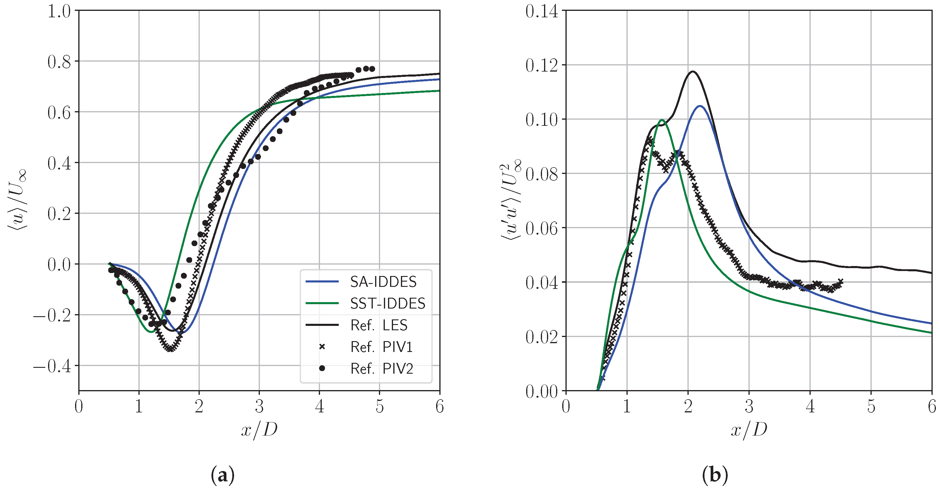
Figure 5a shows the mean longitudinal velocity in the wake centerline. Starting from zero on the surface of the cylinder, it reaches a negative minimum in the recirculation zone and gradually approaches the inflow velocity . A good agreement between the SST-IDDES model and the data from [] is found, particularly in predicting the position and the amplitude of the lower peak, although a significant discrepancy can be observed downstream. The SA-IDDES model instead shows excellent alignment with the data from [], especially with the LES results, reproducing the same profile with minimal offset. The recirculation length , defined in [] as the distance between the center of the cylinder and the point of sign change in the longitudinal velocity, can be observed and calculated from these plots. The results are shown in Table 2, indicating the good correspondence of the SST-IDDES model with the reference [] and a slight overprediction by the SA-IDDES model compared to [].
Figure 5.
Normalized longitudinal velocity at the wake centerline: (a) mean value; (b) variance; reference LES and PIV1 from [] and PIV2 from [].
Table 2.
Comparison of recirculation length data with references.
Figure 5b shows the variance of the longitudinal velocity at the wake centerline, which is zero at the cylinder’s base, reaches two peaks in the experimental data, and then gradually decays toward zero. Once again, we observe a strong correlation between the SA-IDDES model and the reference LES data from [], both of which indicate the presence of an almost invisible first peak and a more pronounced second one. In contrast, the SST-IDDES model only predicts a single peak. However, it should be noted that this model is more appropriately compared with the solution from [], for which no data on this particular quantity is available.
Transversal profiles of averaged longitudinal velocity at different streamwise positions are presented in Figure 6a. The already introduced, most noticeable difference between the two solutions can be observed in the profiles at , where the velocity defect in the near-wake region of the cylinder is predicted with a U-shape by the SA-IDDES model, in perfect agreement with [], and it is predicted with a V-shape by the SST-IDDES model, in accordance with []. Additional calculations (not reported in this manuscript) using a spanwise length of were performed to explore the possibility that our results might be sensitive to the spanwise dimension, as in []. However, we observed the same shape independent of the spanwise length. At and , both shapes tend to resemble a V-shape, both in very good agreement with the respective reference solutions. Further downstream, all profiles gradually flatten, reproducing the measurements of [].
Figure 6.
Streamwise velocity at the wake: (a) mean value; (b) variance; reference LES and PIV1 from [], PIV2 from [], and HWA by Ong et al. [].
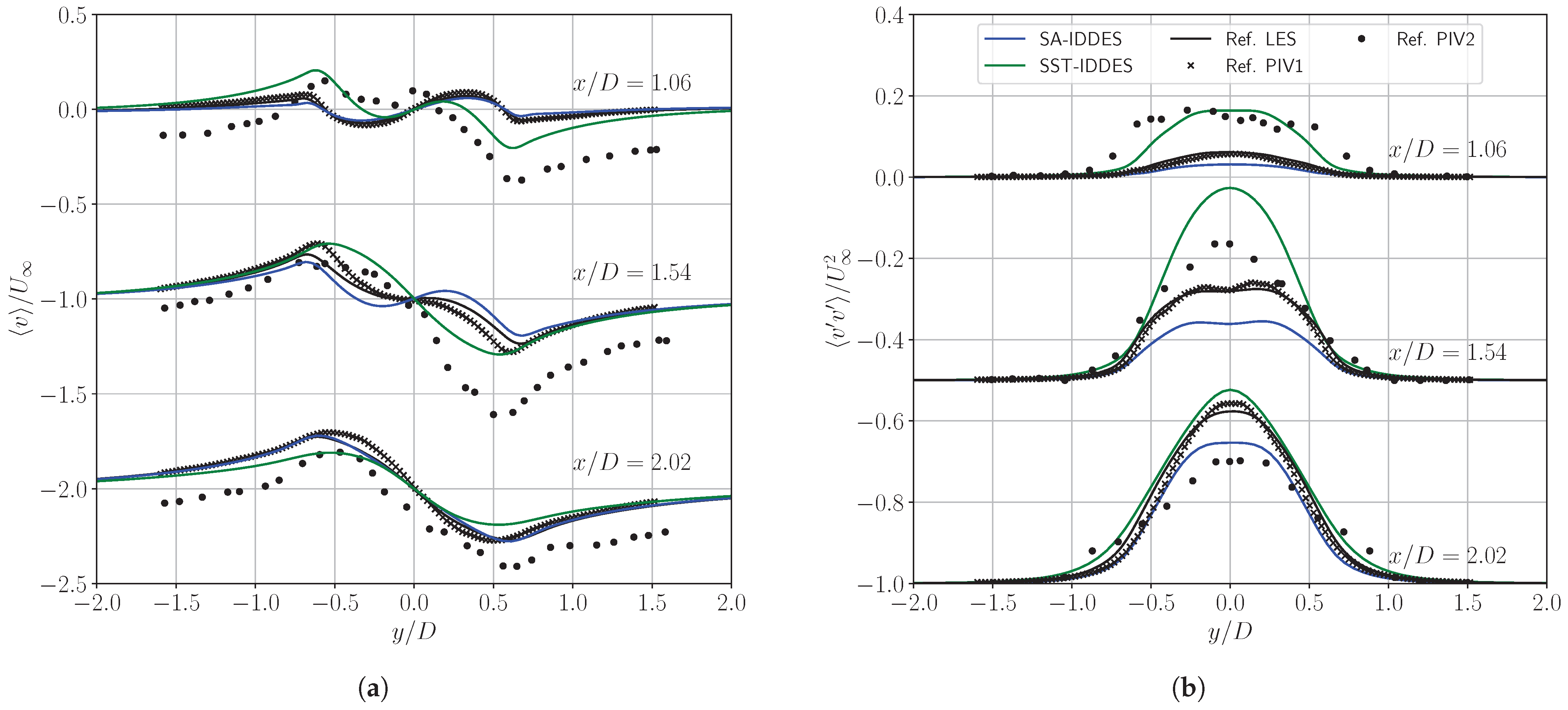
Figure 7a shows profiles along the normal direction of averaged transverse velocity. While the results from the SA-IDDES model closely match those of [], the results from the SST-IDDES model display similar qualitative behavior to both [,], although they are not directly comparable. It is important to note that the experimental data from [] show some inconsistencies, as the profiles do not converge to zero transverse velocity in the undisturbed regions of the flow ( and ). Furthermore, as highlighted in [], the data from [] does not exhibit the expected antisymmetry with respect to , which is present in all other profiles.
Figure 7.
Normal velocity at the wake: (a) mean value; (b) variance; reference LES and PIV1 from [] and PIV2 from [].
Finally, Figure 6b and Figure 7b show, respectively, the variances of the streamwise and transversal velocities along the y-axis. Two peaks can be observed in the longitudinal velocity fluctuations corresponding to the shear layers. Once again, two different profiles can be observed, especially in the very-near-wake region; however, both the position and the amplitude of the peaks are in good agreement with the respective reference data. Hence, the good performance of the SA-IDDES and SST-IDDES models can also be confirmed for the prediction of velocity fluctuations.
Considering that both the SA-IDDES and SST-IDDES are hybrid RANS/LES approaches, offering a reduction in computational cost at the expense of accuracy, both models have shown good performance in this canonical validation test case, confirming the validity of the implementation as well. For the numerical study of the turbine stage, we decided to proceed with the SST-IDDES, which is preferred for internal flows and expected to be superior in the case of boundary layer separation, whose accurate prediction remains an RANS responsibility in DES.
4. Detached Eddy Simulation of sCO2 Turbine
The investigated radial turbine is a prototype developed by Everllence SE (see [] for a discussion on the design of this device). It was designed to investigate the operating behavior of the turbine stage in an air-breathing test rig, which is currently under construction. The turbine features a covered low-specific-speed rotor with 19 blades and a stator consisting of two components: a volute and a nozzle ring with 17 vanes. As the stage under investigation is an early prototype, the volute is currently still under development and not yet available to be included in the study. A meridional view of the whole machine is shown in Figure 8, where a zoomed-in view highlights the labyrinth seals.
Figure 8.
Meridional view of the main channel and the rotor cavities. Labyrinth seals in the rotor cover and in the rear disk cavities are shown enlarged.
4.1. Computational Setup
The rotational speed is defined by a circumferential Mach number of . A Riemann boundary condition specifying a stationary uniform stagnation pressure of 90 bar and temperature of is applied at the inlet. The inlet volute is assumed to generate a homogeneous swirl over the whole annulus, leading to a flow inlet angle of 45° relative to the meridional direction (NACA convention). At the outlet of the diffuser and the backface cavity, a constant static pressure of 45 bar is imposed. The turbulent kinetic energy and specific dissipation rate at the inlet are computed for a given turbulent intensity of 5% and a turbulent viscosity ratio of 3. All walls are treated as adiabatic.
The simulation was performed on a multi-block computational grid consisting of a total of cells. The size of the cells on the walls was set to guarantee values of . The full-crown grid was constructed from a single-passage grid, for which a detailed summary on mesh topology and grid statistics, as well as a mesh sensitivity study, is available in one of our previous works []. A sliding plane is placed at the rotor-stator interface, while the cavities are connected to the main channel by means of arbitrary non-matching interfaces to allow for a higher degree of freedom in the meshing process. Figure 9 shows a detailed view of the mesh in the labyrinth seals. The mesh is progressively coarsened in the axial direction towards the outlets to increase numerical dissipation and prevent the reflection of fluctuations.
Figure 9.
Zoomed-in image of the mesh: (a) straight-through labyrinth seal in the backface cavity; (b) stepped labyrinth seal in the cover disk cavity.
To ensure stability in the case of backflow, a corresponding backflow treatment, which enforces a constant average stagnation enthalpy in the respective outlet plane, is used. Time integration is performed using a dual time-stepping technique, where internal loops are integrated with an implicit LUSGS [] scheme. The physical time step corresponds to six time steps for each blade-passing period.
An RANS simulation was performed up to convergence to initialize the flow field. Subsequently, the computation was run for a time corresponding to 15 rotations to allow for the development of unsteady flow features, which were tracked using probes placed upstream of the rotor blades. Convergence was proven by Fourier transform of the time signal and verification of the dominance of the expected blade-passing frequency. Finally, a simulation with running averaging to collect statistical data was performed for a total time corresponding to five revolutions. The computational cost is estimated as approx. 8000 CPU hours per rotation on a chair-owned HPC cluster with Intel Xeon Gold 6248 CPUs.
4.2. Instantaneous Flow Field
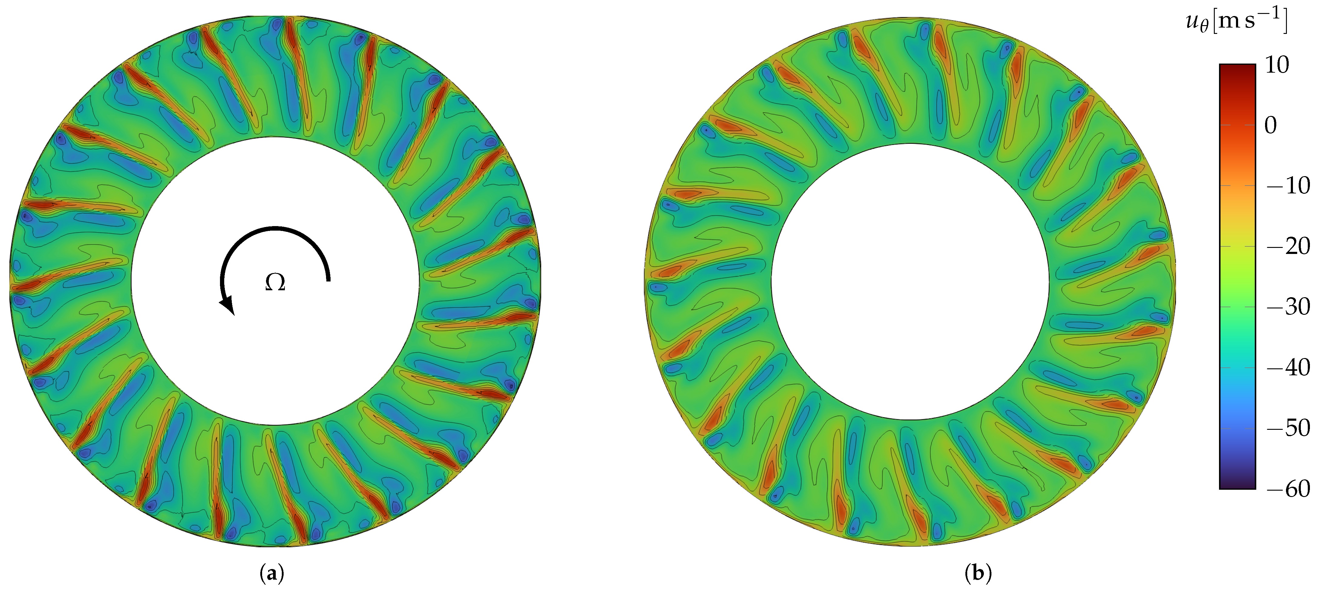
Figure 10a shows the instantaneous contours of tangential velocity, allowing us to analyze the flow in the exducer region of the rotor, directly downstream of the trailing edge. The red regions indicate the velocity defect by the trailing edge wake. In the main passage, a strong cross-passage flow toward the suction side can be observed, which leads to the characteristic passage vortex. In the shroud region, patterns of twin counterrotating passage vortices emerge from the interaction with the cover disk wall boundary layer. Figure 10b illustrates a slice, which was extracted immediately downstream of the connection between the cover disk cavity and the main channel (see Figure 8). The flow is decelerated from the left to the right slice by an increase in area. The velocity defect and passage vortices decay through mixing processes. In the shroud region, the interaction between the leakage and the main passage flow is reflected by a decrease in tangential velocity.
Figure 10.
Circumferential velocity in the rotor exducer region showing (a) the characteristic passage vortices in the main channel and (b) the mixing with the cavity flow, which enters the main passage radially inward and downstream of the rotor. Both slices share the same color map to facilitate the discussion of flow evolution.
4.3. Time-Averaged Results
Figure 11a,b show the time-averaged contours of two quantities: the shielding function, , and the flux blending factor, , which allow for an evaluation of the performed DES. Specifically, the shielding function indicates that only in the most central region of the cavities does the SST-IDDES model switch to the LES mode. In the remaining parts, the RANS model is used (up to 80%). These areas could benefit from a higher resolution, e.g., further mesh refinement, allowing for more isotropic cells. Figure 11b indicates, in turn, that an almost purely central scheme could be used for a very large portion of the cavity regions, suggesting that the mesh quality is sufficient for very accurate discretization of the advective fluxes.
Figure 11.
DES model assessment through meridional view of the rotor cavities: (a) mean value of shielding function, ; (b) flux blending factor, ; and (c) assessment of thermodynamic states through compressibility factor Z.
Figure 11c shows the contours of the compressibility factor , which is a useful criterion for assessing the admissibility of the assumption of an ideal gas (i.e., that the molecules do not possess a volume and do not interact with each other except for elastic collision). Values range from 0.6 to 0.7, with there being a large region of the cover disk cavity where the compressibility factor is particularly low, confirming the strong non-ideal behavior due to high pressure and, therefore, the necessity of a real-gas thermodynamic model.
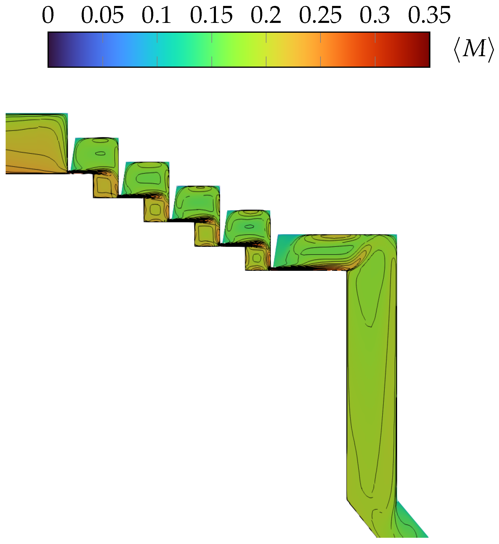
Figure 12 shows a snapshot of the average Mach number with isolines in the cover disk labyrinth seal. The jets through the sealing lips and the areas in which the kinetic energy is dissipated in the chambers are clearly visible. Therefore, the characteristic flow features of this kind of seal can be considered properly resolved for the scope of the current study. Only moderate Mach numbers of around 0.3 occur in the jet through the last throttle. It can therefore be assumed that the seal, in its current configuration, allows too much leakage and still needs to be optimized for use in sCO2. The isolines in Figure 12 indicate flow separation from the corner downstream of the last sealing lip.
Figure 12.
Meridional snapshot of averaged absolute Mach number, M, contours in stepped labyrinth seal mounted on the cover disk cavity.
A significant evolution in the DES results compared to the RANS simulation is evident in Figure 13, which presents a comparison between the instantaneous (Figure 13a) Mach number, the time-averaged (Figure 13b) contours from DES, and the Mach number contours from the RANS simulation (Figure 13c). The RANS solution in the diffuser region lacks the detailed flow structures captured by DES and is characterized by substantial oscillations in the velocity field that hinder convergence. The convergence issues are amplified by enforcing artificial periodicity in single-passage configurations, which leads to a purely axial velocity at the machine centerline. This constraint is unphysical, as confirmed by the instantaneous flow field (see Figure 13a). In contrast, the SST-IDDES model, primarily due to the unsteady nature of DES and its ability to resolve large-scale turbulent structures directly, predicts large recirculation zones along the diffuser walls and flow separation from the spinner. This represents an important advancement, as the incorrect downstream flow predictions and oscillatory behavior detected by the RANS model would likely lead to erroneous predictions of key performance metrics, such as axial thrust.
Figure 13.
Meridional snapshot of diffuser for comparison between RANS and DES: (a) instantaneous Mach number for SST-IDDES; (b) time-averaged Mach number for SST-IDDES; and (c) Mach number for SST-based RANS simulation.
5. Conclusions
In this work, a numerical investigation of a radial turbine designed for supercritical carbon dioxide (sCO2) operation in a full-crown configuration was presented. The turbine is an industrial prototype and includes disk cavities with labyrinth seals, which have a significant impact on pressure distribution, skin friction, and overall turbine performance, including axial thrust, making this study highly relevant for practical applications. The modeling of sCO2’s properties was handled by an efficient spline-based table look-up method, which ensures the same accuracy as the state-of-the-art equations of state for CO2 in predicting non-ideal gas behaviors under high-pressure conditions while significantly reducing computational overhead. The Improved Delayed Detached Eddy Simulation (IDDES) method, first validated on a cylinder flow, allowed for the observation of characteristic flow features that standard RANS approaches fail to capture, highlighting the importance of unsteady, scale-resolving methods to improve predictive capabilities in complex, real-world turbomachinery configurations. Furthermore, the use of a real-gas thermodynamic model throughout the seal design process can be considered crucial to reliable and sustainable machine operation.
The investigation revealed the potential for significant accuracy improvement through mesh refinement in critical regions, such as the rotor cavities, to enhance the quality of the simulation. As there is currently no clear standard for evaluating the quality of DES, a potential direction for future work could involve combining Pope’s criterion with the shifting function used in IDDES, differentiating RANS and LES regions in quality assessment. In the near future, calculations of thrust and power loss related to windage, extracted from DESs, will also be compared with predictions from low-fidelity RANS models. This comparison will help quantify the improvement in predicting global performance parameters due to the enhanced resolution of turbulence in DES. Achieving more accurate predictions is particularly important, as it could directly inform turbine design optimizations, such as the integration of thrust-reducing features like pump-out vanes. Furthermore, the absence of significant 360-degree effects in the flow field suggests that the use of phase-lagged boundary conditions could be explored to reduce computational effort in future simulations.
Author Contributions
Conceptualization, B.L.; methodology, B.L.; software, B.L. and F.L.P.; validation, F.L.P. and B.L.; formal analysis, B.L.; investigation, B.L. and F.L.P.; resources, F.d.M.; data curation, B.L.; writing—original draft preparation, B.L., W.S. and F.L.P.; writing—review and editing, B.L.; visualization, B.L.; supervision, F.d.M.; project administration, F.d.M.; funding acquisition, F.d.M. All authors have read and agreed to the published version of the manuscript.
Funding
The investigations were conducted as part of the joint research program DigITecT in the framework of AG Turbo. The work was supported by the Federal Ministry of Economic Affairs and Energy (BMWE) as per the resolution of the German Federal Parliament under grant number 03EE5117H. The authors gratefully acknowledge AG Turbo and Everllence SE for their support and permission to publish this paper. Federico Lo Presti gratefully acknowledges the financial support of the European Union’s Horizon Europe research and innovation program under Grant Agreement No. 101096286, project MYTHOS (medium-range hybrid low-pollution flexi-fuel/hydrogen sustainable engine). Wojciech Sadowski gratefully acknowledges financial support from the Deutsche Forschungsgemeinschaft (DFG) through SFB/TRR287, Project Number 422037413. The responsibility for the content lies solely with its authors.
Data Availability Statement
Restrictions apply to the turbine geometry Everllence SE proprietary data.
Acknowledgments
The authors gratefully acknowledge Eric Lamballais for sharing the digitalized PIV and LES data published by Parnadeu et al.
Conflicts of Interest
The authors declare no conflicts of interest.
References
- Angelino, G. Carbon Dioxide Condensation Cycles For Power Production. J. Eng. Power 1968, 90, 287–295. [Google Scholar] [CrossRef]
- Guardone, A.; Colonna, P.; Pini, M.; Spinelli, A. Nonideal Compressible Fluid Dynamics of Dense Vapors and Supercritical Fluids. Annu. Rev. Fluid Mech. 2024, 56, 241–269. [Google Scholar] [CrossRef]
- White, M.T.; Bianchi, G.; Chai, L.; Tassou, S.A.; Sayma, A.I. Review of Supercritical CO 2 Technologies and Systems for Power Generation. Appl. Therm. Eng. 2021, 185, 116447. [Google Scholar] [CrossRef]
- Brun, K.; Dennis, R.; Friedman, P. Fundamentals and Applications of Supercritical Carbon Dioxide (Sco2) Based Power Cycles, 1st ed.; Elsevier: Amsterdam, The Netherlands, 2017. [Google Scholar]
- Qi, J.; Reddell, T.; Qin, K.; Hooman, K.; Jahn, I.H.J. Supercritical CO2 Radial Turbine Design Performance as a Function of Turbine Size Parameters. J. Turbomach. 2017, 139, 081008. [Google Scholar] [CrossRef]
- Post, P.; Winhart, B.; di Mare, F. Large Eddy Simulation of a Condensing Wet Steam Turbine Cascade. J. Eng. Gas Turbines Power 2021, 143, 021016. [Google Scholar] [CrossRef]
- Boudin, A.; Dombard, J.; Duchaine, F.; Gicquel, L.; Odier, N.; Lavagnoli, S.; Lopes, G.; Simonassi, L. Analysis of Rotor/Stator Interactions in a High-Speed Low-Pressure Turbine Cascade Using Large-Eddy Simulations. In Proceedings of the European Conference on Turbomachinery Fluid Dynamics and Thermodynamics, Budapest, Hungary, 24–28 April 2023. [Google Scholar] [CrossRef]
- Piomelli, U.; Radhakrishnan, S.; Zhong, L.; Li, M. Wall-Layer Models for Large-Eddy Simulations of High Reynolds Number Non-Equilibrium Flows. In Advances in Turbulence XI; Palma, J., Lopes, A.S., Eds.; Springer: Berlin/Heidelberg, Germany, 2007; Volume 117, pp. 47–54. [Google Scholar] [CrossRef]
- Al-Am, J.; Giauque, A.; Clair, V.; Boudet, J.; Gea-Aguilera, F. Direct-Noise of an Ultrahigh-Bypass-Ratio Turbofan: Periodic-Sector vs. Full-Annulus Large-Eddy Simulations. AIAA J. 2024, 62, 2831–2845. [Google Scholar] [CrossRef]
- Menter, F.R.; Egorov, Y. The Scale-Adaptive Simulation Method for Unsteady Turbulent Flow Predictions. Part 1: Theory and Model Description. Flow Turbul. Combust. 2010, 85, 113–138. [Google Scholar] [CrossRef]
- Spalart, P.; Allmaras, S. A One-Equation Turbulence Model for Aerodynamic Flows. In Proceedings of the 30th Aerospace Sciences Meeting and Exhibit, Reno, NV, USA, 6–9 January 1992. [Google Scholar] [CrossRef]
- Sadowski, W.; Lo Presti, F.; Di Mare, F. Assessment of Hybrid Turbulence Models for the Simulation of Ribbed Channel with Heat Transfer. In Proceedings of the European Conference on Turbomachinery Fluid Dynamics and Thermodynamics, Budapest, Hungary, 24–28 April 2023. [Google Scholar] [CrossRef]
- Karaefe, R.E.; Post, P.; Sembritzky, M.; Schramm, A.; Di Mare, F.; Kunick, M.; Gampe, U. Numerical Investigation of a Centrifugal Compressor for Supercritical CO2 Cycles. In Proceedings of the Volume 11: Structures and Dynamics: Structural Mechanics, Vibration, and Damping; Supercritical CO2, Virtual, Online, 21–25 September 2020; p. V011T31A011. [Google Scholar] [CrossRef]
- Lea, B.; Lo Presti, F.; Sadowski, W.; di Mare, F. Detached Eddy Simulation of a Radial Turbine operated with supercritical Carbon Dioxide. In Proceedings of the 16th European Turbomachinery Conference, Hannover, Germany, 24–28 March 2025; American Society of Mechanical Engineers: New York, NY, USA, 2025. [Google Scholar]
- Keep, J.A.; Jahn, I.H.J. Numerical Loss Investigation of a Small Scale, Low Specific Speed Supercritical CO2 Radial Inflow Turbine. J. Eng. Gas Turbines Power 2019, 141, 091003. [Google Scholar] [CrossRef]
- Zhou, K.; Wang, J.; Xia, J.; Guo, Y.; Zhao, P.; Dai, Y. Design and Performance Analysis of a Supercritical CO2 Radial Inflow Turbine. Appl. Therm. Eng. 2020, 167, 114757. [Google Scholar] [CrossRef]
- Iim, H.; Chen, X.Y.; Zha, G. Detached-Eddy Simulation of Rotating Stall Inception for a Full-Annulus Transonic Rotor. J. Propuls. Power 2012, 28, 782–798. [Google Scholar] [CrossRef]
- Gan, J.; Im, H.S.; Zha, G.C. Delayed Detached Eddy Simulation of Rotating Stall for a Full Annulus Transonic Axial Compressor Stage. In Proceedings of the ASME Turbo Expo 2016: Turbomachinery Technical Conference and Exposition. American Society of Mechanical Engineers Digital Collection, Seoul, Republic of Korea, 13–17 June 2016. [Google Scholar] [CrossRef]
- Menter, F.R. Improved Two-Equation k-Omega Turbulence Models for Aerodynamic Flows. Technical Report A-92183; 1 October 1992. [Google Scholar]
- Spalart, P.; Jou, W.H.; Strelets, M.; Allmaras, S. Comments on the Feasibility of LES for Wings, and on a Hybrid RANS/LES Approach. In Proceedings of the First AFOSR International Conference on DNS/LES, Ruston, LA, USA, 4–8 August 1997. [Google Scholar]
- Span, R.; Wagner, W. A New Equation of State for Carbon Dioxide Covering the Fluid Region from the Triple-Point Temperature to 1100 K at Pressures up to 800 MPa. J. Phys. Chem. Ref. Data 1996, 25, 1509–1596. [Google Scholar] [CrossRef]
- Laesecke, A.; Muzny, C.D. Reference Correlation for the Viscosity of Carbon Dioxide. J. Phys. Chem. Ref. Data 2017, 46, 013107. [Google Scholar] [CrossRef] [PubMed]
- Huber, M.L.; Sykioti, E.A.; Assael, M.J.; Perkins, R.A. Reference Correlation of the Thermal Conductivity of Carbon Dioxide from the Triple Point to 1100 K and up to 200 MPa. J. Phys. Chem. Ref. Data 2016, 45, 013102. [Google Scholar] [CrossRef] [PubMed]
- Kunick, M. Fast Calculation of Thermophysical Properties in Extensive Process Simulations with the Spline-Based Table Look-Up Method (SBTL); VDI Verlag: Düsseldorf, Germany, 2018. [Google Scholar] [CrossRef]
- Shur, M.L.; Spalart, P.R.; Strelets, M.K.; Travin, A.K. A Hybrid RANS-LES Approach with Delayed-DES and Wall-Modelled LES Capabilities. Int. J. Heat Fluid Flow 2008, 29, 1638–1649. [Google Scholar] [CrossRef]
- Travin, A.K.; Shur, M.L.; Strelets, M.; Spalart, P.R. Physical and Numerical Upgrades in the Detached-Eddy Simulation of Complex Turbulent Flows. In Advances in LES of Complex Flows: Proceedings of the Euromech Colloquium 412, Munich, Germany, 4–6 October 2000; Springer: Dordrecht, The Netherlands, 2002. [Google Scholar]
- Spalart, P.R.; Deck, S.; Shur, M.L.; Squires, K.D.; Strelets, M.K.; Travin, A. A New Version of Detached-eddy Simulation, Resistant to Ambiguous Grid Densities. Theor. Comput. Fluid Dyn. 2006, 20, 181–195. [Google Scholar] [CrossRef]
- Gritskevich, M.S.; Garbaruk, A.V.; Schütze, J.; Menter, F.R. Development of DDES and IDDES Formulations for the K-ω Shear Stress Transport Model. Flow, Turbul. Combust. 2012, 88, 431–449. [Google Scholar] [CrossRef]
- van Albada, G.D.; van Leer, B.; Roberts, W.W. A Comparative Study of Computational Methods in Cosmic Gas Dynamics. In Upwind and High-Resolution Schemes; Hussaini, M.Y., van Leer, B., Van Rosendale, J., Eds.; Springer: Berlin/Heidelberg, Germany, 1997; pp. 95–103. [Google Scholar] [CrossRef]
- Liou, M.S. A sequel to AUSM, Part II: AUSM+-up for all speeds. J. Comput. Phys. 2006, 214, 137–170. [Google Scholar] [CrossRef]
- Spalart, P.; Shur, M.; Strelets, M.; Travin, A. Sensitivity of Landing-Gear Noise Predictions by Large-Eddy Simulation to Numerics and Resolution. In Proceedings of the 50th AIAA Aerospace Sciences Meeting Including the New Horizons Forum and Aerospace Exposition, Nashville, TN, USA, 9–12 January 2012. [Google Scholar] [CrossRef]
- Breuer, M. Towards Technical Application of Large Eddy Simulation. ZAMM—J. Appl. Math. Mech./Z. Angew. Math. Mech. 2001, 81, 461–462. [Google Scholar] [CrossRef]
- Parnaudeau, P.; Carlier, J.; Heitz, D.; Lamballais, E. Experimental and numerical studies of the flow over a circular cylinder at Reynolds number 3900. Phys. Fluids 2008, 20, 085101. [Google Scholar] [CrossRef]
- Lourenco, L.M.; Shih, C. Characteristics of the plane turbulent near wake of a cylinder, A particle image velocimetry study. Unpublished.
- Ong, L.; Wallace, J.M. The velocity field of the turbulent very near wake of a circular cylinder. Exp. Fluids 1996, 20, 441–453. [Google Scholar] [CrossRef]
- Ma, X.L.; Karamanos, G.S.; Karniadakis, G.E. Dynamics and low-dimensionality of a turbulent near wake. J. Fluid Mech. 2000, 410, 29–65. [Google Scholar] [CrossRef]
- Beaudan, P.; Moin, P. Numerical Experiments on the Flow Past A Circular Cylinder at Sub-Critical Reynolds Number; Stanford University: Stanford, CA, USA, 1994. [Google Scholar]
- Mahesh, K.; Constantinescu, G.; Moin, P. A numerical method for large-eddy simulation in complex geometries. J. Comput. Phys. 2004, 197, 215–240. [Google Scholar] [CrossRef]
- Kravchenko, A.G.; Moin, P. Numerical studies of flow over a circular cylinder at ReD = 3900. Phys. Fluids 2000, 12, 403–417. [Google Scholar] [CrossRef]
- Franke, J.; Frank, W. Large eddy simulation of the flow past a circular cylinder at ReD = 3900. J. Wind Eng. Ind. Aerodyn. 2002, 90, 1191–1206. [Google Scholar] [CrossRef]
- D’Alessandro, V.; Montelpare, S.; Ricci, R. Detached–eddy simulations of the flow over a cylinder at Re = 3900 using OpenFOAM. Comput. Fluids 2016, 136, 152–169. [Google Scholar] [CrossRef]
- Pereira, F.S.; Vaz, G.; Eça, L.; Girimaji, S.S. Simulation of the flow around a circular cylinder at Re=3900 with Partially-Averaged Navier-Stokes equations. Int. J. Heat Fluid Flow 2018, 69, 234–246. [Google Scholar] [CrossRef]
- Lodato, G.; Domingo, P.; Vervisch, L. Three-dimensional boundary conditions for direct and large-eddy simulation of compressible viscous flows. J. Comput. Phys. 2008, 227, 5105–5143. [Google Scholar] [CrossRef]
- Spalart, P.R.; Streett, C. Young-Person’s Guide to Detached-Eddy Simulation Grids; Technical report; Langley Research Center: Hampton, VA, USA, 2001. [Google Scholar]
- Lea, B.; di Mare, F.; Franz, H. Numerical Investigation of the Axial Thrust Load of a Prototype Radial Turbine for Supercritical CO2 Cycles. In Proceedings of the Turbo Expo: Power for Land, Sea, and Air, London, UK, 24–28 June 2024; American Society of Mechanical Engineers: New York, NY, USA, 2024; Volume 88049, p. V011T28A010. [Google Scholar]
- Yoon, S.; Jameson, A. Lower-upper symmetric-Gauss-Seidel method for the Euler and Navier-Stokes equations. AIAA J. 1988, 26, 1025–1026. [Google Scholar] [CrossRef]
Disclaimer/Publisher’s Note: The statements, opinions and data contained in all publications are solely those of the individual author(s) and contributor(s) and not of MDPI and/or the editor(s). MDPI and/or the editor(s) disclaim responsibility for any injury to people or property resulting from any ideas, methods, instructions or products referred to in the content. |
© 2025 by the authors. Published by MDPI on behalf of the EUROTURBO. Licensee MDPI, Basel, Switzerland. This article is an open access article distributed under the terms and conditions of the Creative Commons Attribution (CC BY-NC-ND) license (https://creativecommons.org/licenses/by-nc-nd/4.0/).