Abstract
Understanding the deformation mechanisms of materials at cryogenic temperatures is crucial for cryogenic engineering applications. In situ neutron diffraction is a powerful technique for probing such mechanisms under cryogenic conditions. In this study, we present the development of a compact cryogenic environment (CCE) designed to facilitate in situ neutron diffraction experiments under mechanical loading at temperatures as low as 77 K with a maximum cooling rate of 6 K/min. The CCE features a polystyrene foam cryogenic chamber, aluminum blocks serving as neutron-transparent cold sinks, a liquid nitrogen dosing system for cryogen delivery, a nitrogen gas flow control system for thermal management, a process controller for temperature control, and a pair of thermally isolated grip adapters for mechanical testing. The CCE achieves reliable temperature control with minimal neutron attenuation. Utilizing this setup, we conducted three in situ neutron diffraction tensile tests on a 316L stainless steel at 77, 173, and 298 K, respectively. The results highlight the pronounced effects of cryogenic temperatures on the material’s deformation mechanisms, underscoring both the significance of cryogenic deformation studies and the effectiveness of the CCE.
1. Introduction
Cryogenic applications drive materials research across diverse fields, including cryogenic storage and transport, space and aerospace engineering, and superconducting technologies. These applications demand either reliable mechanical performance of structural alloys, such as austenitic stainless steels [1,2], aluminum alloys [1,3], titanium alloys [1,4], and high entropy alloys [5,6]), or controlled deformation in specialized functional materials, such as Invar alloys [7], superconductors [8,9,10], and shape memory alloys [11,12]. Consequently, the need to understand deformation mechanisms at cryogenic temperatures has grown significantly.
In situ neutron diffraction is a powerful tool for probing deformation mechanisms at cryogenic temperatures [13,14,15,16]. Unlike in situ microscopy techniques (e.g., scanning or transmission electron microscopy), neutron diffraction enables statistical analysis over large sample volumes (hundreds of cubic millimeters) owing to the high penetration depth of neutrons. However, these advantages come with significant challenges in cryogenic sample environments. Engineering materials diffractometers are typically equipped with large-footprint load frames for mechanical testing, leaving limited space to integrate cryogenic devices. Moreover, interfacing the cryogenic environment with the load frame is complicated, as the grips—acting as heat sources—must be inserted into the cryogenic chamber. To address this, neutron instrument scientists have developed vacuum chambers with closed-cycle refrigerators and thermally isolating grip adapters, achieving reliable operation down to 6 K, 7 K, and 4.8 K at load capacities of 100 kN, 50 kN, and 10 kN on ENGIN-X at ISIS [17,18], TAKUMI at J-PARC [19,20], RESA at JRR-3 JAEA [21], respectively.
For higher cryogenic temperatures (>77 K), more compact vacuum chambers with closed-loop liquid-nitrogen (LN2) systems have been implemented at TAKUMI [19] and SMARTS at LANL [22], reaching 100 K and 90 K, respectively. Nevertheless, these systems remain bulky or operationally complex. To overcome these limitations, we have developed a compact cryogenic environment (CCE) tailored for integration with the load frame on the engineering materials diffractometer VULCAN at the Spallation Neutron Source, Oak Ridge National Laboratory.
2. Design of the CCE
The compact cryogenic environment (CCE) was designed to operate with liquid nitrogen as the cryogen, with optimization for stable thermal management and minimal neutron attenuation. Figure 1 shows the CCE design for in situ neutron diffraction experiments at VULCAN. The system consists of a polystyrene foam chamber, neutron path blocks, and grip adapters, supplemented by a liquid nitrogen dosing unit, a nitrogen gas flow system, and a process controller.
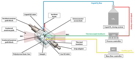
Figure 1.
Design view of the CCE for in situ neutron diffraction experiments on VULCAN.
The chamber is constructed from closed-cell extruded polystyrene (Styrofoam, DuPont, Wilmington, DE, USA), chosen for its excellent thermal insulation (thermal conductivity ≈ 0.035 W m−1 K−1). Its external dimensions are 203 mm × 165 mm × 127 mm with a wall thickness of 25.4 mm. Access openings include a 20 mm × 10 mm rectangular slot in the lid for extensometer attachment and two 6 mm-diameter ports at diagonal corners for liquid and gaseous nitrogen inlets.
To mitigate neutron attenuation by liquid nitrogen, dedicated neutron path blocks were incorporated to exclude cryogen from the incident and scattered beam paths when the chamber is filled. Two sets of blocks, fabricated from Styrofoam and aluminum alloy, were tested to evaluate neutron transparency and thermal performance. The incident beam block provides an 18 mm × 22 mm aperture, sufficient to accommodate all standard VULCAN beam sizes (≤ 8 mm × 8 mm) with ample margin for mechanical loading experiments. The scattered-beam blocks were shaped to match the pyramidal detector viewing geometry, with separate blocks covering detector banks BK1 and BK2.
Mechanical coupling between the sample and the load frame is achieved through custom grip adapters that simultaneously provide thermal insulation from the heated hydraulic grips. The design employs a counterbore socket connection between a large threaded steel socket and a smaller flat-headed rod. Thermal insulation rings and disks are inserted between the socket/rod assembly and the sample-side rod, with a lock ring ensuring a secure fit. This geometry supports both tensile and compressive loading; under compression, it passes the compressive forces on the insulating components directly; under tension, it converts tensile forces on the sample into compressive forces on the insulating components, thereby exploiting the higher compressive strength of insulation materials. The metallic parts are fabricated from hardened 4140 alloy steel (thermal conductivity ≈ 42.6 W m−1 K−1), while the insulating components are made of G10 fiberglass laminate (thermal conductivity ≈ 0.228 W m−1 K−1). With a nominal compressive strength of ~450 MPa at room temperature, the G10 components enable reliable load transfer up to ~200 kN.
Cryogen delivery is managed by a LN2 microdosing system (Norhof, Ede, Netherlands) that automatically supplies liquid nitrogen from a 100 L dewar. The flow rate is regulated proportionally to the analog output signal of a closed-loop process controller, while the dewar is placed on a floor scale to monitor consumption. Thermal management on the warming side is provided by facility nitrogen gas at ambient temperature, delivered through a digitally controlled manifold equipped with solenoid valves and mass flow controllers.
Temperature regulation is achieved with a Eurotherm 2048 closed-loop process controller (Eurotherm, Worthing, UK). Thermocouples mounted at the sample center provide the primary feedback signal, while the controller output drives the LN2 dosing system. A secondary thermocouple located near one grip adapter records the thermal gradient along the sample during testing.
3. Setup of the CCE with Load Frame
The CCE was evaluated using 316L stainless steel tensile samples mounted on the MTS servo hydraulic load frame (100 kN capacity) on VULCAN (Figure 2). The load frame was oriented at 45° to the incident neutron beam, enabling scattered neutrons from lattice planes parallel to the loading axis to be detected by BK1, while those scattered transverse to the loading axis were captured by BK2. The sample has a round bar dumbbell shape with a gauge diameter of 6.35 mm and gauge length of 30 mm.
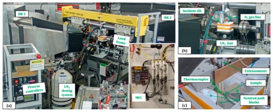
Figure 2.
Setup of the CCE with the load frame at VULCAN: (a) overall view, (b) close-up of the cryogenic chamber, and (c) internal view with the chamber lid removed.
Temperature monitoring was achieved using type E and type K thermocouples (Omega, Norwalk, CT, USA). Two type E thermocouples were affixed to the Sample with Kapton tape (DuPont, Wilmington, DE, USA): one at the gauge center for feedback control and the other just outside the gauge section for gradient monitoring. Additional type K thermocouples were attached to a grip socket and to one hydraulic grip to record their temperatures. Type E thermocouple signals were acquired through process controllers, while type K thermocouples were logged via a separate I/O device.
Macroscopic strain was measured using an extensometer (MTS, Eden Prairie, MN, USA) equipped with two Al2O3 rods. The tensile samples had a gauge length of 30 mm and a diameter of 6.35 mm. Two samples were annealed at 1050 °C for 1 h for cryogenic tensile tests, while one was annealed at 950 °C for 1 h for room-temperature testing. The 950 °C-1 h and 1050 °C-1 h samples are expected to have minor differences in texture and grain size that could affect the tensile properties but not to the extent of altering the trend of temperature effect on the tensile properties.
4. Performance of the CCE
Three sets of in situ neutron diffraction tests were performed with the CCE to evaluate its performance in terms of neutron attenuation, temperature stability, and tensile loading. All measurements were conducted using an incident beam size of 8 mm × 6 mm (width × height), a chopper frequency of 30 Hz, a center wavelength of 2 Å, and a wavelength band of 2.8 Å. The proton beam operated at a power of 1.7 MW. Neutron diffraction data were reduced and analyzed using the VDRIVE software package [23], which enables batch processing of single-peak fitting and Rietveld refinement through GSAS [24].
4.1. Neutron Attenuation
Figure 3 presents two-minute diffraction patterns of a 316L stainless steel sample under different CCE configurations. Relative to the sample-only condition, the addition of the chamber, neutron path blocks, and liquid nitrogen led to a significant reduction in peak intensity (Figure 3a), attributable to neutron attenuation by the Styrofoam, aluminum, and LN2. Nevertheless, when the diffraction data are plotted on a logarithmic scale, the peak shapes and relative intensities remain consistent across configurations (Figure 3b), indicating that attenuation does not distort the diffraction information.
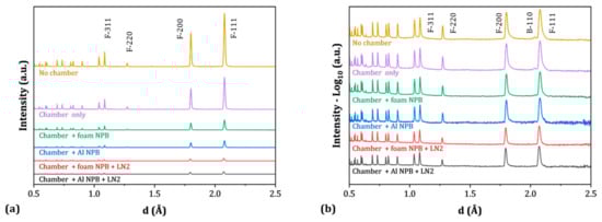
Figure 3.
Diffraction patterns of a 316L stainless steel sample under different CCE configurations: (a) linear intensity scale and (b) logarithmic intensity scale. Peak notations: F = FCC, B = BCC.
The diffraction patterns are dominated by reflections from the primary face-centered cubic (FCC) phase of 316L stainless steel. Minor peaks corresponding to a body-centered cubic (BCC) phase, likely arising from residual ferrite after annealing, are also observed. However, these weaker reflections become indistinguishable under conditions of higher neutron attenuation.
To quantify neutron attenuation, the integral intensities of ten individual diffraction peaks were extracted using single-peak fitting in VDRIVE. A pseudo-Voigt function convoluted with a back-to-back exponential function was employed as the peak profile. Signal and background intensities were obtained separately from the fits (Figure 4a), where the signal corresponds to the fitted peak intensity above background and the background reflects incoherent sample scattering plus instrument contributions, as described in our previous study [25]. Normalized values were obtained by dividing signal and background intensities by those of the no-chamber baseline (Figure 4b). Signal-to-background (STB) ratios were calculated for each condition (Figure 4c) and further normalized to the no-chamber baseline (Figure 4d).
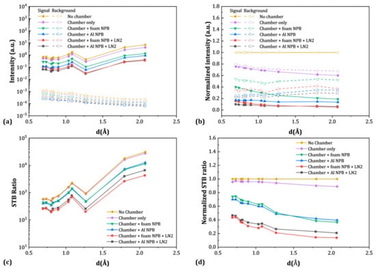
Figure 4.
Signal and background intensities of selected diffraction peaks as a function of d-spacing: (a) fitted values, (b) normalized intensities, (c) STB ratios, and (d) normalized STB ratios.
The attenuation of signal and background intensities exhibits both material-dependent and mixed wavelength-dependent behavior. As shown in Figure 4a, signal intensities display a zig-zag trend with increasing d-spacing, primarily reflecting the hkl-dependent factors (including multiplicity, Lorentz factor, and Debye-Waller factor) that determine the reflection intensities of the studied FCC lattice structure, while background intensities generally decrease with wavelength, consistent with typical attenuation behavior as the absorption cross sections typically increase with that of wavelength. With the addition of the chamber, neutron path blocks, and LN2, both signal and background intensities decrease. After normalization (Figure 4b), signal intensities are reduced by 25–40% with the chamber alone, 60–80% with the chamber plus Styrofoam neutron path blocks, and 85–95% with LN2 present. The aluminum path blocks produce less wavelength-dependent attenuation, with reductions comparable to the long-wavelength end of the foam-block case. Background reductions are consistently smaller than those of the signals. Interestingly, the background attenuation trends vary with configuration: the foam blocks and LN2 reduce wavelength sensitivity, whereas the aluminum blocks exhibit an apparent reversal in wavelength dependence. This mixed wavelength dependence of background attenuation is not fully understood but may arise from hydrogen-rich foam moderating relatively fast neutrons. It is noted that the attenuation by foam and aluminum NPB is found almost equivalent, which is associated with the density of the two materials. While hydrogen in the foam is significantly stronger than the aluminum in neutron incoherent scattering and moderation, the total number of hydrogen atoms is much lower than that of aluminum atoms in the aluminum block.
Despite these reductions, STB ratios remain at promising levels across all conditions. As shown in Figure 4c, the lowest absolute STB ratio under the chamber + blocks + LN2 condition exceeds 200—an order of magnitude above the commonly cited threshold of 20 for high-quality peak fitting. After normalization (Figure 4d), the reduction in STB ratio is modest (5–12%) with the chamber alone, showing only minor wavelength dependence. With foam or aluminum neutron path blocks, reductions increase to 20–65% and become more wavelength dependent. The further addition of LN2 leads to STB reductions of 55–85%. Notably, the configuration with chamber + aluminum blocks + LN2 shows less STB reduction than the chamber + foam blocks + LN2 case, likely due to geometric differences: the foam blocks were hand cut, whereas the aluminum blocks were precisely machined.
4.2. Temperature Control
The performance of the CCE in temperature regulation was assessed during controlled cooling and warming cycles for tensile tests at 77 K and 173 K. For the 77 K test, foam neutron path blocks were used to minimize LN2 consumption, while the 173 K test employed Al blocks to enhance thermal management, as their higher conductivity allowed more effective heat transfer from the LN2 reservoir. In addition, a nitrogen gas flow was introduced during the 173 K test to improve warming control.
The CCE demonstrated excellent cooling control from room temperature (RT) down to 150 K and reasonable control from 150 K to 77 K. As shown in Figure 5 and Figure 6, sample temperatures closely followed the commanded cooling rate of 3 K/min, with Al blocks providing more stable control than foam blocks. Fluctuations appeared when the sample temperature dropped below ~175 K with foam blocks and ~150 K with Al blocks, corresponding to the LN2 level approaching the gauge region. Improved performance was observed in subsequent cooling stages when nitrogen gas flow (10 L/min) was applied, yielding smoother control down to 77 K. Further improvement was observed when increasing the cooling rate to 6 K/min, which maintained stable control from RT to 77 K. But in general, caution should be considered for materials that are sensitive to temperature changes (e.g., temperature-induced martensitic transformation) in the range of 150 K–77 K given the non-ideal cooling control of this device.
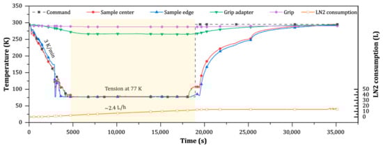
Figure 5.
Temperature profiles and LN2 consumption during cooling, tensile testing at 77 K, and subsequent warming.
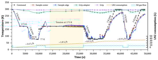
Figure 6.
Temperature profiles and LN2 consumption during cooling, holding at 77 K, warming, tensile testing at 173 K, and repeated cooling–warming cycles between 77 and 298 K.
At cryogenic setpoints, the CCE showed reliable holding control at 77 K, 83 K, and 173 K. While immersion at 77 K was relatively straightforward, the elevated holding temperatures at 83 K and 173 K required precise regulation above the LN2 surface. As shown in Figure 6, both conditions were maintained stably with Al blocks, though slight fluctuations were noted late in the 173 K test, likely caused by loosening of the thermocouple during sample deformation. Notably, during holding at 77 K, the grip adapter temperature remained as high as 265 K, while the grips themselves cooled by only ~3 K, demonstrating effective thermal isolation from the chamber.
The warming process proved more challenging. From 77 K to 150 K, sample temperatures followed the commanded rate of 3 K/min closely, but above 150 K the warming lagged progressively. This limitation reflects the insufficient “heating power” provided by nitrogen gas alone to maintain a rapid warming rate.
LN2 consumption varied significantly with setpoint, cooling rate, chamber configuration, and gas flow. At 77 K, the consumption rate was ~2.4 L/h with foam blocks and ~3.6 L/h with Al blocks (Figure 5 and Figure 6). The addition of nitrogen gas flow increased consumption to ~4.4 L/h, while raising the cooling rate to 6 K/min pushed it to ~5.9 L/h even without gas flow. In comparison, holding at 173 K required only ~1.8 L/h, reflecting the reduced thermal demand at higher setpoints.
4.3. In Situ Tension
Three tensile tests were conducted on 316L stainless steel at 77, 173, and 298 K, respectively. All experiments were displacement-controlled, with equivalent strain rates of ~6 × 10⁻⁵ s−1 at 77 and 173 K and ~6 × 10⁻⁴ s−1 at 298 K. Neutron diffraction data were collected continuously throughout loading and segmented into 3 min sub-runs for the cryogenic tests and 15 s sub-runs for the room-temperature test. The macroscopic stress–strain curves are presented in Figure 7, while the evolving diffraction patterns are shown as 2D and 3D contour maps in Figure 8. Representative diffraction patterns from the first and last sub-runs are given in Figure 9, along with an example of a full-pattern Rietveld refinement for the 77 K test at Run 50 [Figure 9b].
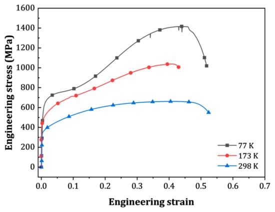
Figure 7.
Tensile stress–strain curves of the 316L stainless steel tested at 77, 173 and 298 K.
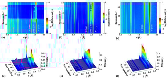
Figure 8.
Contour plots of diffraction patterns in the loading direction during tension tests at (a,d) 77 K, (b,e) 173 K, and (c,f) 298 K. Panels (a–c) show 2D plots; panels (d–f) show the corresponding 3D plots. Peak notations: F = FCC, B = BCC, H = HCP.
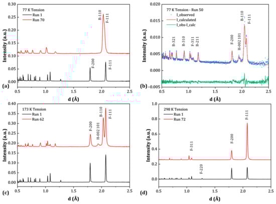
Figure 9.
Diffraction patterns in the loading direction for the first and last sub-runs during tension tests at (a) 77 K, (c) 173 K, and (d) 298 K. (b) Example of full-pattern Rietveld refinement for sub-run 50 during the 77 K test. Peak notations: F = FCC, B = BCC, H = HCP.
The stress–strain behavior highlights the strong influence of temperature on deformation. At 298 K, the steel yields at ~350 MPa and gradually hardens to ~660 MPa at 40% strain. At 173 K, the yield stress increases to ~460 MPa, followed by pronounced strain hardening to ~1040 MPa at 40% strain. At 77 K, the effect is even more dramatic, with the steel yielding at ~630 MPa and hardening continuously to ~1420 MPa at 44% strain. A notable feature at 77 K is the onset of a secondary hardening regime beginning at ~10% strain, which is absent at higher temperatures.
The different hardening behaviors reflect temperature-dependent deformation mechanisms. At room temperature, plasticity is dominated by FCC dislocation slip, as evidenced by peak broadening and the significant increase of 111 peak intensity [width and color change in Figure 8c,f and Figure 9d]. At 173 K, diffraction data reveal the onset of FCC-to-HCP (hexagonal close-packed) martensitic transformation at Run 20 (stress ~550 MPa, strain ~1.2%), followed by FCC-to-BCC transformation at Run 28 (stress ~710 MPa, strain ~10%). These transformations are well-known contributors to enhanced strain hardening in austenitic stainless steels [26,27,28]. At 77 K, the martensitic transformations occur earlier, with FCC-to-HCP detected at Run 24 (stress ~550 MPa, strain ~0.5%) and FCC-to-BCC at Run 27 (stress ~720 MPa, strain ~3%). After fracture, the diffraction pattern at 77 K shows merged FCC and BCC peaks [Figure 9a], in contrast to the distinct three-phase pattern observed at 173 K [Figure 9c]. The disappearance of HCP peaks indicates a complete HCP-to-BCC transformation, while the peak merging suggests large interphase or intergranular strains due to phase-specific hardening and load sharing. Detailed elaboration on the above findings will be presented in our following paper that focuses on the deformation mechanisms of 316L stainless steel over a wide range of temperatures.
During the 77 K test, a sharp drop in diffraction intensity occurred at Run 35 [Figure 8a,c], caused by unintentional displacement of the foam incident path block. LN2 leaked into the incident neutron path, attenuating the beam and reducing the diffraction signal by nearly fivefold. Despite the reduced intensity, the data quality remained sufficient for quantitative analysis. As demonstrated in Figure 9b, full-pattern Rietveld refinement of Run 50 yielded reliable fits, confirming the robustness of the CCE setup for in situ diffraction even under less-than-ideal conditions.
5. Summary and Future Development
In this work, we have developed a CCE that enables in situ neutron diffraction experiments under mechanical loading up to 100 kN at temperatures as low as 77 K with a maximum cooling rate of 6 K/min. The system integrates a polystyrene foam chamber for thermal insulation, aluminum blocks serving as both neutron pathways and cold sinks, a liquid nitrogen microdosing system for controlled cryogen delivery, an ambient-temperature nitrogen gas line for thermal management, and thermally isolated grip adapters for mechanical testing. The CCE demonstrates reasonable neutron transparency and effective temperature control. Using this setup, we conducted in situ tensile tests on a 316L stainless steel at 77, 173, and 298 K. The results highlight the pronounced influence of cryogenic temperatures on deformation mechanisms, thereby underscoring both the scientific importance of cryogenic studies and the effectiveness of the CCE as an enabling tool.
Future improvements will focus on further optimizing the system. Planned developments include redesigning the aluminum neutron path blocks with hollow geometries to reduce mass and attenuation, incorporating cartridge heaters to enhance warming-up control as well as attaching type E thermal couples via spot welding. These refinements will improve efficiency, extend temperature control flexibility, and broaden the range of applications for the CCE in advanced neutron diffraction studies.
Author Contributions
Conceptualization, D.Y., Y.C. and K.A.; methodology, D.Y.; software, K.A.; validation, D.Y. and Y.C.; formal analysis, D.Y.; investigation, D.Y.; resources, D.Y. and H.S.; data curation, D.Y.; writing—original draft preparation, D.Y.; writing—review and editing, D.Y., Y.C., H.S. and K.A.; visualization, D.Y.; supervision, K.A.; project administration, D.Y.; funding acquisition, K.A. All authors have read and agreed to the published version of the manuscript.
Funding
This research received no external funding.
Data Availability Statement
The data presented in this study are available on request from the corresponding author.
Acknowledgments
The neutron diffraction experiments were carried out at the Spallation Neutron Source (SNS), which is the U.S. Department of Energy (DOE) user facility at the Oak Ridge National Laboratory, sponsored by the Scientific User Facilities Division, Office of Basic Energy Sciences. This research used resources at the Spallation Neutron Source, a DOE Office of Science User Facility operated by the Oak Ridge National Laboratory. The beam time was allocated to BL-7 VULCAN on proposal numbers IPTS-33787 and IPTS-34714. The authors gratefully acknowledge Jamie Molaison and Jasmine Hinton for their support with the LN2 microdosing system, Bogdan Vacaliuc for assistance in logging LN2 consumption, and Mariano Ruiz-Rodriguez for support with gas flow software control.
Conflicts of Interest
The authors declare no conflicts of interest.
References
- Umezawa, O. Review of the Mechanical Properties of High-Strength Alloys at Cryogenic Temperatures. Mater. Perform. Charact. 2021, 10, 3–15. [Google Scholar] [CrossRef]
- Anoop, C.R.; Singh, R.K.; Kumar, R.R.; Jayalakshmi, M.; Prabhu, T.A.; Tharian, K.T.; Murty, S.V.S.N. A Review on Steels for Cryogenic Applications. Mater. Perform. Charact. 2021, 10, 16–88. [Google Scholar] [CrossRef]
- Park, D.-H.; Choi, S.-W.; Kim, J.-H.; Lee, J.-M. Cryogenic Mechanical Behavior of 5000- and 6000-Series Aluminum Alloys: Issues on Application to Offshore Plants. Cryogenics 2015, 68, 44–58. [Google Scholar] [CrossRef]
- Zang, M.C.; Niu, H.Z.; Yu, J.S.; Zhang, H.R.; Zhang, T.B.; Zhang, D.L. Cryogenic Tensile Properties and Deformation Behavior of a Fine-Grained near Alpha Titanium Alloy with an Equiaxed Microstructure. Mater. Sci. Eng. A 2022, 840, 142952. [Google Scholar] [CrossRef]
- Cui, K.; Liaw, P.K.; Zhang, Y. Cryogenic-Mechanical Properties and Applications of Multiple-Basis-Element Alloys. Metals 2022, 12, 2075. [Google Scholar] [CrossRef]
- Gao, X.; Chen, R.; Liu, T.; Fang, H.; Qin, G.; Su, Y.; Guo, J. High-Entropy Alloys: A Review of Mechanical Properties and Deformation Mechanisms at Cryogenic Temperatures. J. Mater. Sci. 2022, 57, 6573–6606. [Google Scholar] [CrossRef]
- Choi, S.; Won, J.; Lee, J.-J.; Lee, H.-K.; Kim, S.-M.; Cho, C.; Kwon, D. Evaluation of Cryogenic Mechanical Properties of Resistance Seam-Welded Invar Alloy Sheet by Instrumented Indentation Test. J. Mar. Sci. Eng. 2020, 8, 1009. [Google Scholar] [CrossRef]
- Ekin, J.W. Strain Effects in Superconducting Compounds. In Advances in Cryogenic Engineering Materials; Clark, A.F., Reed, R.P., Eds.; Springer: Boston, MA, USA, 1984; Volume 30, pp. 823–836. [Google Scholar]
- Ruf, J.P.; Paik, H.; Schreiber, N.J.; Nair, H.P.; Miao, L.; Kawasaki, J.K.; Nelson, J.N.; Faeth, B.D.; Lee, Y.; Goodge, B.H.; et al. Strain-Stabilized Superconductivity. Nat. Commun. 2021, 12, 59. [Google Scholar] [CrossRef]
- Zhang, J.; Wu, H.; Zhao, G.; Han, L.; Zhang, J. A Review on Strain Study of Cuprate Superconductors. Nanomaterials 2022, 12, 3340. [Google Scholar] [CrossRef]
- Nespoli, A.; Ninarello, D.; Fanciulli, C. A Review on Shape Memory Alloys with Martensitic Transition at Cryogenic Temperatures. Metals 2023, 13, 1311. [Google Scholar] [CrossRef]
- Sato, S.; Tobe, H.; Sawada, K.; Tokoku, C.; Nakagawa, T.; Sato, E.; Araki, Y.; Xu, S.; Xu, X.; Omori, T.; et al. Shape Memory Alloys for Cryogenic Actuators. Commun. Eng. 2025, 4, 124. [Google Scholar] [CrossRef] [PubMed]
- An, K.; Chen, Y.; Stoica, A.D. Vulcan: A “Hammer” for High-Temperature Materials Research. MRS Bull. 2019, 44, 878–883. [Google Scholar] [CrossRef]
- Liu, D.; Yu, Q.; Kabra, S.; Jiang, M.; Forna-Kreutzer, P.; Zhang, R.; Payne, M.; Walsh, F.; Gludovatz, B.; Asta, M.; et al. Exceptional Fracture Toughness of Crconi-Based Medium- and High-Entropy Alloys at 20 Kelvin. Science 2022, 378, 978–983. [Google Scholar] [CrossRef] [PubMed]
- Wang, Y.; Liu, B.; Yan, K.; Wang, M.; Kabra, S.; Chiu, Y.L.; Dye, D.; Lee, P.D.; Liu, Y.; Cai, B. Probing Deformation Mechanisms of a Fecocrni High-Entropy Alloy at 293 and 77 K Using in Situ Neutron Diffraction. Acta Mater. 2018, 154, 79–89. [Google Scholar] [CrossRef]
- Naeem, M.; He, H.; Zhang, F.; Huang, H.; Harjo, S.; Kawasaki, T.; Wang, B.; Lan, S.; Wu, Z.; Wang, F.; et al. Cooperative Deformation in High-Entropy Alloys at Ultralow Temperatures. Sci. Adv. 2020, 6, eaax4002. [Google Scholar] [CrossRef]
- Oliver, E.; Evans, B.; Chowdhury, M.; Major, R.; Kirichek, O.; Bowden, Z. Novel Testing Chamber for Neutron Scattering Measurements of Internal Stresses in Engineering Materials at Cryogenic Temperatures. Meas. Sci. Technol. 2008, 19, 034019. [Google Scholar] [CrossRef]
- Kirichek, O.; Timms, J.D.; Kelleher, J.F.; Down, R.B.E.; Offer, C.D.; Kabra, S.; Zhang, S.Y. Sample Environment for Neutron Scattering Measurements of Internal Stresses in Engineering Materials in the Temperature Range of 6 K to 300 K. Rev. Sci. Instrum. 2017, 88, 025103. [Google Scholar] [CrossRef]
- Stefanus, H.; Aizawa, K.; Kowasaki, T.; Nakamoto, T.; Hemmi, T.; Iwahashi, T. Cryogenic Loading Devices for Materials Science and Engineering Studies at J-Parc. In Proceedings of the 21st Meeting of the International Collaboration on Advanced Neutron Sources (ICANS-21), ‘Dawn of High Power Neutron Sources and Science Applications’, Mito, Japan, 29 September–3 October 2014. [Google Scholar]
- Kawasaki, T.; Harjo, S.; Gong, W.; Mao, W.; Yamashita, T.; Ito, T.; Aizawa, K. Cryogenic Tensile Testing System for Simultaneous in Situ Neutron Diffraction and Digital Image Correlation Strain Analysis. Rev. Sci. Instrum. 2025, 96, 093901. [Google Scholar] [CrossRef]
- Tsuchiya, Y.; Suzuki, H.; Umeno, T.; Machiya, S.; Osamura, K. Development of a Cryogenic Load Frame for a Neutron Diffractometer. Meas. Sci. Technol. 2010, 21, 025904. [Google Scholar] [CrossRef]
- Woodruff, T.R.; Krishnan, V.B.; Clausen, B.; Sisneros, T.; Livescu, V.; Brown, D.W.; Bourke, M.A.M.; Vaidyanathan, R. Design, Implementation, and Testing of a Cryogenic Loading Capability on an Engineering Neutron Diffractometer. Rev. Sci. Instrum. 2010, 81, 063903. [Google Scholar] [CrossRef]
- An, K. Data Reduction and Interactive Visualization Software for Event Mode Neutron Diffraction; ORNL Report, ORNL-TM-2012; ORNL: Oak Ridge, TN, USA, 2012; Volume 621. [Google Scholar]
- Larson, A.C.; Von Dreele, R.B. General Structure Analysis System (GSAS). Los Alamos National Laboratory LAUR Report: Los Alamos, NM, USA, 1994; pp. 86–748. [Google Scholar]
- Yu, D.; Chen, Y.; Conner, D.; Berry, K.; Skorpenske, H.; An, K. Effect of Collimation on Diffraction Signal-to-Background Ratios at a Neutron Diffractometer. Quantum Beam Sci. 2024, 8, 14. [Google Scholar] [CrossRef]
- Tao, K.; Wall, J.J.; Li, H.; Brown, D.W.; Vogel, S.C.; Choo, H. In Situ Neutron Diffraction Study of Grain-Orientation-Dependent Phase Transformation in 304l Stainless Steel at a Cryogenic Temperature. J. Appl. Phys. 2006, 100, 123515. [Google Scholar] [CrossRef]
- Zheng, C.; Zhen, Q.; Wang, Y.; Li, N. Low Temperature Macro- and Micro-Mechanical Behavior of an Ultrafine-Grained Metastable 304 Austenitic Stainless Steel Investigated by in Situ High-Energy X-Ray Diffraction. Mater. Sci. Eng. A 2021, 817, 141295. [Google Scholar] [CrossRef]
- Li, S.; Withers, P.J.; Kabra, S.; Yan, K. The Behaviour and Deformation Mechanisms for 316l Stainless Steel Deformed at Cryogenic Temperatures. Mater. Sci. Eng. A 2023, 880, 145279. [Google Scholar] [CrossRef]


Disclaimer/Publisher’s Note: The statements, opinions and data contained in all publications are solely those of the individual author(s) and contributor(s) and not of MDPI and/or the editor(s). MDPI and/or the editor(s) disclaim responsibility for any injury to people or property resulting from any ideas, methods, instructions or products referred to in the content. |
© 2025 by the authors. Licensee MDPI, Basel, Switzerland. This article is an open access article distributed under the terms and conditions of the Creative Commons Attribution (CC BY) license (https://creativecommons.org/licenses/by/4.0/).