1. Introduction
Flexible pavement traffic loading is transferred through both asphalt concrete (AC) and bounded or unbounded layers to the subgrade layer. The insufficient load-bearing capacity of the subgrade layer may result in significant maintenance costs. Seasonal variations in the moisture content of the subgrade soil may give rise to significant volumetric changes in clay-type soils, leading to the significant contraction and cracking of the pavement. Two approaches can be used to improve weak subgrades. In the first approach, the in situ soil would be replaced with quarried soil that can meet the specifications. In the second approach, the soil would be stabilized using chemical additives to improve the load-bearing capacity [
1]. For soil stabilization, several types of additives including lime, cement, enzymes, lignin, fly ash, resins, and other chemicals can be used [
2,
3,
4]. The selection of the proper stabilization agent depends on factors such as cost, soil type, and the desired performance [
5].
Lime stabilization can be used to improve the performance of subgrade soils. The condition-improving effects of lime stabilization depend on the type of clay soil, curing time, lime content, and construction quality [
6]. Lime has been traditionally used to chemically improve soft clay soil stability [
7]. Lime stabilization leads to significant environmental benefits through reducing the need for material hauling and extraction. Chemical stabilization improves soil behavior in several ways. It decreases plasticity, improves compactability, and increases the load-bearing capacity and durability. In many recent studies, CBR test results show that the lime-stabilized soils have a longer-term compressive strength, and the stabilized soils have a higher resistance to frost heave damage [
8]. Field studies have shown that lime stabilization is most effective when applied to fine-grained soils [
9]. The National Lime Association (NLA) recommends lime stabilization for soils that have a minimum of 25% passing sieve #200 and a minimum plasticity index of 10 [
10]. Previous studies show that the optimum lime percentage for weak clays is between 2 and 8 percent by weight of the dry soil [
11].
Fly ash, derived from the combustion of coal in thermal power plants, serves as a valuable resource for enhancing the performance and longevity of flexible pavements through subgrade stabilization. This byproduct, enriched with trace elements such as zinc (Zn), copper (Cu), nickel (Ni), and chromium (Cr), is classified into two categories using the American Society for Testing and Materials (ASTM): Class C and Class F [
12]. Class F fly ash, characterized by a lime content of less than 7% (CaO), requires the addition of cementing agents like cement, lime, or CaO-containing materials, combined with water [
13]. This combination initiates the formation of cementitious compounds, making Class F fly ash a crucial component in construction processes that demand superior cementitious properties.
In the realm of subgrade stabilization for flexible pavements, fly ash proves to be an indispensable solution. While it may exhibit limited cementitious properties compared to lime and cement, fly ash, especially from Class C and Class F categories, plays a significant role as a secondary binder. When introduced to a small amount of activator, these fly ashes undergo a chemical reaction, resulting in the formation of cementitious compounds that enhance the strength of soft soil. The cost-effectiveness, ready availability, and environmental friendliness of fly ashes makes them an attractive choice for soil stabilization [
13]. Class C fly ashes, originating from the combustion of sub-bituminous coal, boast high cementing properties due to their elevated free CaO content [
12]. Notably, lignite-based Class C fly ash, with a higher CaO content exhibits remarkable self-cementing characteristics. In contrast, Class F fly ashes, produced from the burning of anthracite and bituminous coal, demonstrate slightly lower self-cementing properties due to their composition [
14]. The meticulous selection of fly ash, considering its class and lime content, is imperative for construction applications seeking improved cementitious properties that are vital for optimal performance and longevity in flexible pavements. Class C fly ash boasts a lime content surpassing 20%, demonstrating a distinctive self-cementitious behavior when exposed to moisture [
4]. This inherent property makes Class C fly ash particularly desirable for soil stabilization applications in pavement construction. The enhanced lime content in Class C fly ash not only contributes to its self-cementing capabilities, but also underscores its efficacy in imparting strength and durability to soil structures within pavement systems.
Moreover, the utilization of Class C fly ash for soil stabilization in pavement construction carries a significant environmental benefit. Through repurposing this industrial byproduct, which might otherwise pose disposal challenges, as a resource for enhancing soil properties, the approach aligns with sustainable construction practices. This environmentally conscious use of fly ash contributes to a positive environmental footprint, showcasing the potential for transforming waste materials into valuable assets in infrastructure development.
Cement kiln dust (CKD) is a byproduct of Portland cement production, which gets captured in exhaust gases using cotton filters or in an electrostatic precipitator. CKD generally contains between about 30 and 40% CaO, and about 20 to 25% pozzolanic material [
15]. Most CKDs tend to generate relatively high pH levels when mixed with water. The higher alkalinity and finer particle size in addition to their cementitious properties make these materials suitable for soil stabilization applications. The CKD stabilization mechanism is similar to lime stabilization and the chemical reactions depend on the physical and chemical properties of the used CKD [
16].
In this research, the effect of stabilization on decreasing the critical strains and, therefore, improving the fatigue and rutting life of the pavement is investigated. The assessments were conducted with consideration of different types of additives at varying contents, subgrade soil types, and stabilization thicknesses for different pavement structures. The ‘Universal’ model was used to enable the non-linear elastic behavior analysis of the granular layers, including an aggregate base layer, stabilized, and natural subgrade. The analysis was performed using the non-linear pavement analysis software, NonPAS, to assess the asphalt concrete life, the stabilized subgrade fatigue life, and the subgrade rutting life.
2. Research Significance
This study holds particular importance in addressing the pressing challenges associated with weak subgrades, offering valuable insights into the optimal strategies for enhancing subgrade stability and, consequently, the overall efficiency and durability of flexible pavements. Through delving into the intricacies of soil replacement, with a focus on subgrade stabilization using lime, CFA, and CKD, the research not only contributes to the environmental sustainability of construction practices, but also sheds light on factors such as additive content, stabilization thickness, and soil type that significantly impact subgrade stabilization. The investigation’s focus on critical strains, fatigue life, and rutting life, considering diverse additives, subgrade soil types, and stabilization thicknesses, adds a comprehensive dimension to the understanding of subgrade stabilization’s multifaceted benefits. Importantly, the use of fly ash is anticipated to result in a substantial reduction in the environmental footprint, showcasing the potential for sustainable construction practices. By building on the global literature and leveraging the capabilities of NonPAS for non-linear analysis, this research significantly contributes to advancing the knowledge base, fostering informed decisions in pavement design and maintenance practices worldwide.
3. Background
The exploration of subgrade soil stabilization’s impact on the performance and lifespan extension of flexible pavements has garnered increasing research attention. Qubain et al. [
17] observed a remarkable enhancement in the resilient modulus and California Bearing Ratio (CBR) by 4 to 5 times after applying 5% lime, leading to a reduced required thickness and subsequently lower construction costs [
17]. Similar findings were reported by Vorobieff and Murphy [
18], emphasizing that a lower thickness design facilitates higher compaction levels, thereby improving the overall pavement performance. Addressing weak subgrades, a study conducted for the Michigan Department of Transportation (MDOT) by Elseifi and Dhakal [
1] demonstrated that lime stabilization costs only
$3.70 per sq.m., compared to soil replacement’s
$8.81 per sq.m. Gautreau et al. [
19] reinforced the preference for lime stabilization over soil replacement (325% versus 225%) in terms of the resilient modulus stiffness improvement, as evidenced by results from the accelerated pavement test (APT), showing a significant reduction in permanent deformation with lime stabilization [
19].
Solanki et al. [
7] delved into the impact of lime, CKD, and CFA stabilization on the resilient modulus of fine-grained soils. The study emphasized the non-linear nature of soil behavior concerning triaxial stresses, highlighting that the increase in lime content does not necessarily correlate with a higher resilient modulus. It was concluded that an optimum lime content should be determined for each soil type, a notion supported by other researchers [
20,
21].
In a study by Wu et al. [
22] on the stabilization of silty clay subgrades using cement and lime, results indicated a higher increase in the resilient modulus with cement stabilization in wetter climates. Furthermore, the study delineated the substantial role of the aggregate base layer in permanent deformation under cement stabilization, while lime stabilization exhibited a more balanced contribution from the base, stabilized subgrade, and natural subgrade in total deformation.
Mishra et al. [
23] conducted a life-cycle cost analysis for lime-stabilized pavements, revealing a significant decrease in pavement thickness based on the optimum lime percentages and traffic loading. Construction cost estimates showed reductions of 9.4%, 6.8%, 9.1%, and 12.4% for traffic equivalent single axle loadings (ESALs) of 60,000–100,000, 100,000–200,000, 300,000–600,000, and 600,000–1,000,000, respectively. The Queensland Department of Transport and Main Roads, in a field study between 2009 and 2012, determined that a lime-stabilized subgrade should ideally be at least 250 mm, preferably 300 mm, in thickness for optimal performance [
24].
Field studies by Péterfalvi et al. [
25] corroborated a minimum lime stabilization depth of 25–35 cm for satisfactory subgrade performance.
Selvi, in 2015, [
26] employed a mechanistic-empirical analysis to evaluate critical pavement responses for lime-treated subgrades in flexible pavements. The study demonstrated that subgrade stabilization significantly improves rutting life. Design thickness reductions varied with subgrade CBR and traffic loading, leading to the development of charts accounting for stabilization effects during pavement design based on subgrade soil strength and traffic loading.
Adeyanju et al. [
27] investigated the effect of using two waste materials of rice husk ash (RHA) and cement kiln dust (CKD) in enhancing the mechanical strength of subgrade soils. Results indicated that soil stabilization results in a 52.5% layer thickness reduction and at least
$60,000 reduction in material costs for a standard 200 m road in Nigeria, regardless of the stabilizer type.
Nazari [
28] investigated the performance of pavement structures with a chemically stabilized subgrade, which were modeled using a 3D finite element method (FEM), and for different sections, the required thickness to prevent fatigue failure was determined. The research suggests that for pavements with stabilized subgrades with projected high fatigue lives, an M-E design approach should focus on other distresses such as bottom-up and top-down cracking, transverse cracking, rutting, and roughness.
Solanki and Zaman [
29], used the linear elastic analysis and KENLAYER software to assess the effect of additives and soil type on the required stabilized section thickness. Fatigue performance design curves for the stabilized subgrade layers were developed. It was shown that as the stabilized layer thickness increased, the fatigue life differences associated with different additives reduced. Additionally noted was the positive correlation between the augmentation of the resilient modulus in the stabilized layer and the enhancement of fatigue life in the asphalt layer. In conclusion, it was firmly established that the augmentation of the thickness in the stabilized subgrade layer leads to a significant extension in the fatigue life of both the asphalt layer and the stabilized subgrade layer. This underscores the critical role of stabilization layer thickness in positively influencing the fatigue performance of the overall pavement structure, emphasizing the practical implications for pavement design and longevity.
Nagrale and Patil [
30] employed finite element analysis to estimate pavement life with subgrade stabilization, revealing substantial improvements. The estimated pavement life for lime, fly ash, and fiber stabilization of subgrade soil increased by 6.49, 4.37, and 3.26 times, respectively.
A notable limitation in the existing literature is the assumption of a linear elastic pavement response, which may not accurately represent the in situ behavior of the aggregate base layer, natural subgrade, and stabilized subgrade [
31,
32,
33]. Subgrade stabilization typically leads to an increase in resilient modulus, challenging the traditional assumption of moduli descending in magnitude order from the top layers to the bottom layers. The resulting pavement structure often assumes an inverted configuration, and the use of a non-linear elastic modulus is more reflective of the in situ response [
34]. To overcome the constraints associated with linear elastic analysis, this research utilized non-linear pavement analysis software, such as NonPAS. Several variables affecting soil stabilization were considered, including subgrade soil type (CL or CH), additive type and content (3, 6, and 9% of hydrated lime, 5, 10, and 15% of cement kiln dust (CKD), and 5, 10, and 15% of class C fly ash (CFA)), three stabilization thicknesses (15, 30, and 45 cm), and four pavement sections with varying thicknesses.
In summary, the collective findings underscore the advantages of subgrade soil stabilization, showcasing the improvements in the performance, cost-effectiveness, and longevity of flexible pavements. The research spans diverse stabilizing agents, soil types, and conditions, providing a comprehensive understanding of the intricate interactions within pavement systems. The application of non-linear pavement analysis software addresses the limitations inherent in linear elastic analysis, contributing to a more realistic assessment of in situ responses and further enhancing the knowledge base for effective pavement design and maintenance.
4. Materials and Methods
4.1. Modeling and Non-Linear Analysis
The characterization of the elastic modulus in unbound pavement materials often relies on the resilient modulus, denoted as
MR. This parameter, defined as the ratio of cyclic deviatoric stress to recoverable strain after repeated loading cycles, directly quantifies the stiffness of unbound materials in pavement systems [
35]. The resilient modulus can be calculated using the following equation:
where
represents deviatoric stress and
represents recoverable strain. Notably, previous studies indicate that the load response behavior of coarse and fine aggregates is stress-level dependent, suggesting the necessity of non-linear analysis for accurate pavement assessment [
36,
37,
38,
39,
40,
41,
42]. Additional research underscores the influence of confining and deviatoric stress levels on the behavior of chemically stabilized soils [
32,
43,
44,
45,
46,
47].
Various non-linear models, including
K-
θ, Bilinear, Uzan, Universal, and MEPDG, have been proposed [
48,
49,
50,
51,
52]. The ‘Universal’ model, applied in this research, accommodates both fine-grained and coarse-grained soils. Developed by Witczak and Uzan in 1998, it integrates octahedral shear stress (
τoct) and volumetric stress (
θ) to evaluate the combined effect of stresses on the resilient modulus [
51]. The model, expressed as follows:
where
is the atmospheric pressure (101.325 kPa) and
θ and
can be calculated as follows:
The Universal model, which considers the octahedral shear stress (
τoct) and volumetric stress (
θ), has not been previously implemented in publicly available non-linear pavement analysis software based on layered theory, such as KENLAYER. In this study, the NonPAS pavement analysis program was utilized for its capability in conducting both linear and non-linear elastic analyses for flexible pavements, accommodating up to six circular loadings using the layered theory [
50].
NonPAS facilitates a mechanistic-empirical design, considering five damage mechanisms, including fatigue cracking, subgrade rutting, and crushing. The program offers three options for defining stress point locations, enhancing flexibility in the analysis. In comparison to other software like KENLAYER, NonPAS stands out with its inclusion of seven non-linear models—Universal, Uzan, K-θ, MEPDG, Bilinear, NCHRP 1-28, and Semi-log—providing researchers and practitioners with expanded modeling capabilities.
The NonPAS program demonstrates its superiority through allowing the use of principal stresses for non-linear analysis, a feature absent in other pavement analysis software like KENLAYER. The results obtained from NonPAS versus other software, such as KENLAYER and WinJULEA, highlight the accuracy and reliability of NonPAS in analyzing flexible pavements [
53].
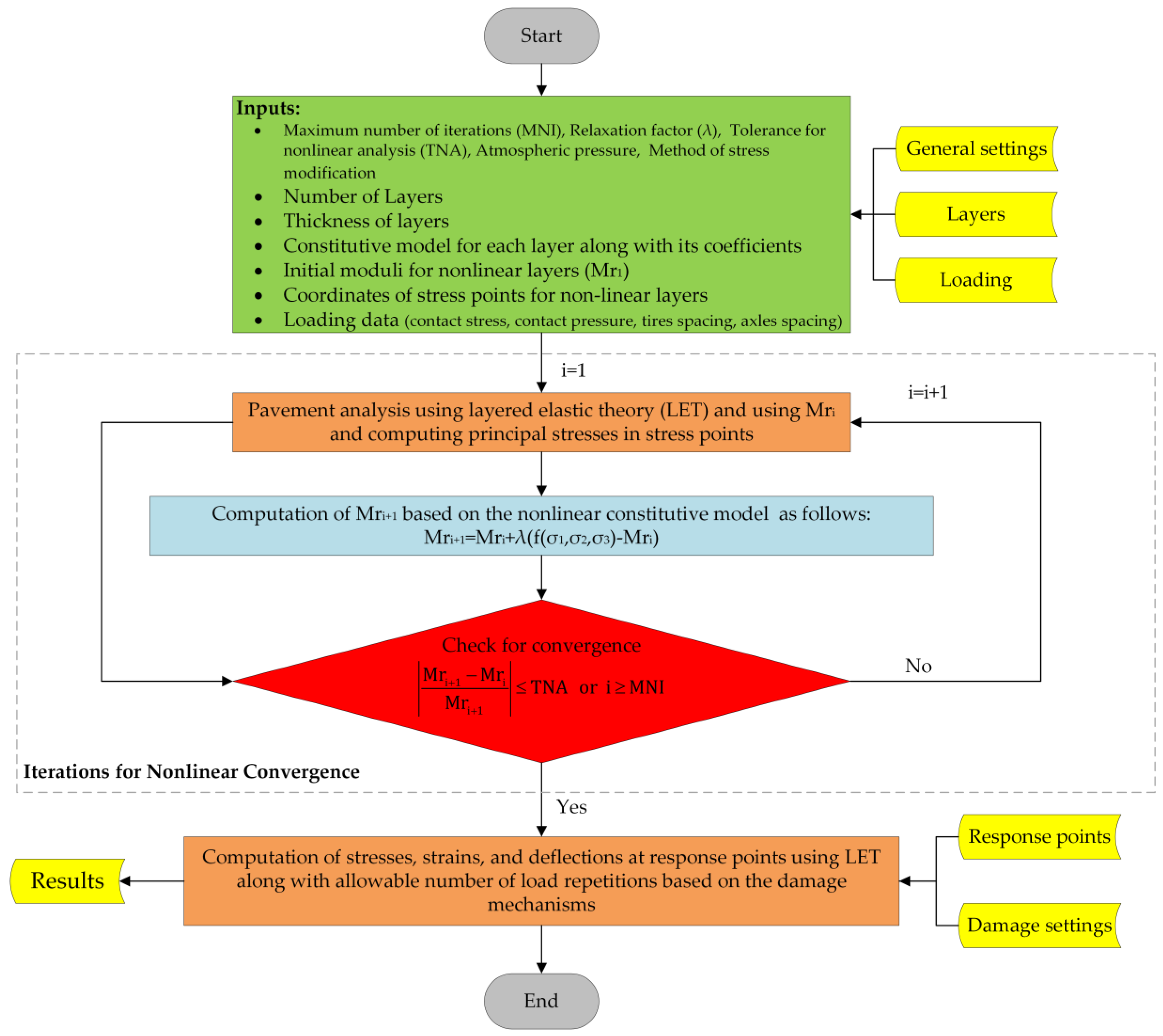
The NonPAS pavement analysis software consists of an intuitive interface featuring five tabs dedicated to settings, layers, loading, response points, and damage settings, complemented by two tabs specifically presenting results and converged non-linear analysis data. The ‘results’ tab provides an extensive array of detailed information encompassing stresses, strains, deflections in x, y, and z directions, along with shear and principal stresses and strains. Notably, the software facilitates the seamless export of results to a text file, enhancing its accessibility and documentation. A visual representation of the systematic procedure for conducting NonPAS non-linear analysis on flexible pavements is illustrated in
Figure 1, offering a clear and comprehensive guide for users. This user-friendly design and robust functionality make NonPAS a valuable tool for in-depth and effective pavement analysis, contributing to advancements in pavement engineering and design practices.
In summary, the utilization of the ‘Universal’ model in NonPAS, coupled with its comprehensive non-linear analysis capabilities, sets it apart from other pavement analysis software, making it a valuable tool for researchers and practitioners seeking accurate and reliable assessments of flexible pavement behavior.
4.2. Material Properties
The function of a stabilized subgrade is similar to that of a subbase layer in a pavement structure [
54]. Therefore, the pavement sections were assumed to comprise four layers (without a subbase layer). The response of stabilized and natural subgrade soil and the aggregate base were considered to be non-linear, whereas the asphalt concrete layer response was assumed to be linear. To calibrate the non-linear Universal model for the stabilized and natural subgrade material, the resilient moduli data reported by Solanki et al. [
55] were used. The data included moduli for various additive content and types (3, 6, and 9% of hydrated lime, 5, 10, and 15% of CKD and CFA for two types of clay soils). The data from Richardson et al. [
56] were also used to calibrate the Universal model for aggregate base layer material.
Solanki et al. [
55] and Richardson et al. [
56] conducted a resilient modulus measurements using the American Association of State Highway and Transportation Officials (AASHTO) T307, “Standard Method of Test for Determining the Resilient Modulus of Soils and Aggregate Materials”. In the study by Solanki et al. [
55], 15 loading sequences were applied with cyclic stress magnitudes ranging from 12.41 to 62.05 kPa and confining pressure ranging from 13.79 to 41.37 kPa, encompassing both stabilized and natural subgrade soils. Richardson et al. [
56] focused on crushed aggregates, applying deviatoric stresses between 20.7 and 276 kPa and confining pressures ranging from 20.7 to 138 kPa. The loading mode adopted was cyclic haversine, featuring a loading time of 0.1 s and a resting time of 0.9 s. These standardized testing procedures contribute to the reliability and consistency of the reported resilient modulus data.
The investigated clay soils were CL (i.e., low plasticity) and CH (i.e., high plasticity) per unified classification or A-6 and A-7-6 per AASHTO classification, respectively. The liquid and plastic limits were 37% and 11% for the subgrade soil type CL, and 58% and 29% for the subgrade soil type CH, respectively [
55]. In addition, the nominal maximum aggregate size (NMAS) for the dolomite crushed aggregate base layer was 19 mm [
56].
The MATLAB
® curve fitting toolbox [
57] was employed to calibrate the Universal model for subgrade and base materials. The calibration results and the densities for the natural and the stabilized subgrade soils at different stabilization percentages that were reported by Solanki et al. [
55] and tested per ASTM D698 are provided in
Table 1.
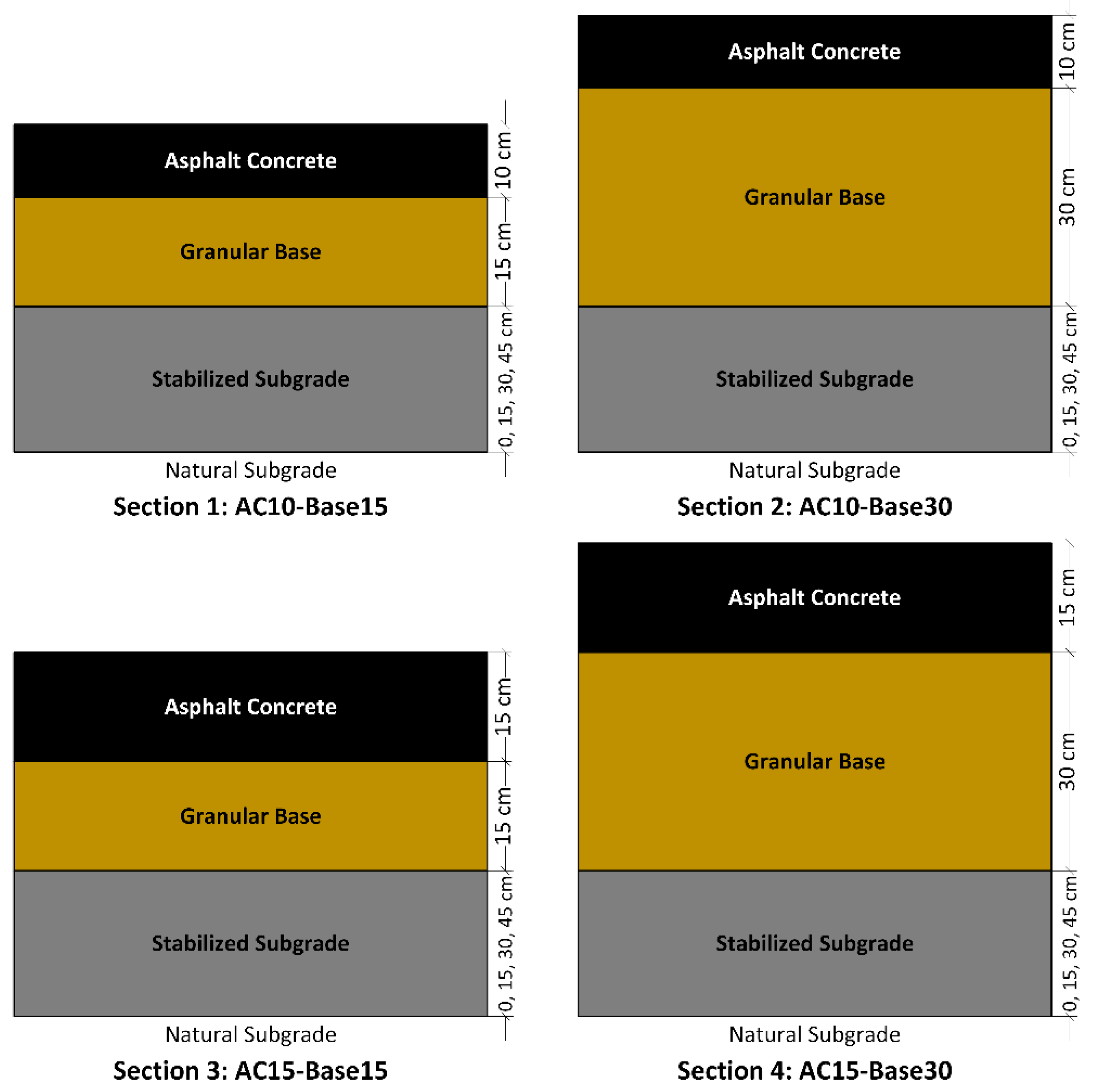
In this investigation, four distinct pavement structures comprising asphalt concrete layers, aggregate bases, and subgrade soils (both natural and stabilized subgrades) were meticulously examined. The NonPAS program was employed to conduct a comprehensive analysis of each structure at three distinct stabilization depths—15 cm, 30 cm, and 45 cm—utilizing the mechanistic-empirical method. The schematic representation of these pavement structures is depicted in
Figure 2, while
Table 2 provides an overview of the properties associated with asphalt concrete, aggregate base, as well as stabilized and natural subgrade materials.
For non-linear analysis, four different damage mechanisms of AC layer fatigue, stabilized subgrade layer fatigue, rutting of the subgrade, and advanced crushing of the stabilized subgrade were considered.
Within the framework of the Asphalt Institute (AI) pavement design methodology, the criterion for restricting fatigue cracking, denoted as the number of traffic load repetitions (
), is intricately linked to the maximal horizontal tensile strain observed at the base of the asphalt concrete layer. To quantify the fatigue life of flexible pavements, the Asphalt Institute provides a prescriptive approach, encapsulated in Equation (5) [
58]:
where
is the maximum horizontal tensile strain at the bottom of the asphalt concrete layer and
is the elastic modulus of the asphalt concrete layer in kPa.
In the Asphalt Institute equation for rutting (Equation (6)), the number of load repetitions to reach rutting failure is inversely proportional to the vertical strain (
) at the top of the subgrade soil [
59]:
Per recommendations of the South African Mechanistic Design Method (SAMDM), the allowable number of load repetitions to limit the fatigue life of a stabilized layer (
) can be calculated using Equation (7) [
60]:
where
SF is the shift factor for fatigue crack propagation, which is derived from the thickness of the stabilized layer. The shift factor curve is shown in
Figure 3.
is the tensile strain at the bottom of the stabilized layer,
is the strain at crush initiation, and c and d are constant coefficients.
is dependent on the quality of stabilized materials, and
c and
d are dependent on the desired reliability level. In this study, material quality is considered C
4 (
equal to 145), and the reliability level is considered to be 90%.
c and
d are considered as 6.84 and 7.63, respectively.
The life of the stabilized subgrade layer can also be estimated using the crushing damage model proposed by the SAMDM. According to the SAMDM, crushing damage is broken down into crush initiation and advanced crushing phases. Only advanced crushing is considered for estimating the life of the stabilized subgrade since crush initiation is not a sign of pavement failure. Advanced crushing is defined when a 10 mm rutting appears at the surface of the stabilized layer. In Equation (8), the advanced crushing damage model is provided [
61]:
where
SR is defined by Equation (9), which is the compressive stress on top of the stabilized layer (
divided by the unconfined compressive strength (UCS) of the stabilized subgrade layer:
The preliminary analysis in this study showed that advanced crushing does not derive the overall pavement life due to large numbers for . This is because the subgrade layer is located at a relatively deep level and, therefore, compressive stresses are reduced, and subgrade soils do not experience high compressive stress levels. As a result, is always higher than fatigue and rutting lives. Therefore, in the final results, the advanced crushing damage mechanism was not considered.
As previously outlined, NonPAS provides users with three distinct options for specifying stress point locations within the pavement structure and modifying stresses during non-linear analysis. In this investigation, the third option is employed, involving the placement of stress points at the midpoint of the non-linear layers. Tensile stresses are then adjusted in accordance with the material’s maximum tensile strength, utilizing the Mohr’s failure envelope. The traffic loading is characterized by an 8.2 ton single standard axle, featuring a contact pressure of 586 kPa. This approach in stress point definition and modification within NonPAS ensures a nuanced and accurate representation of the pavement’s response under varying conditions, enhancing the reliability and precision of the analysis results.
Figure 4 illustrates the locations of pavement responses within the NonPAS software, encompassing the center and edge of the tires, as well as midway between dual tires. The estimation of rutting and fatigue lives for the modeled pavements relies on the identification of the most critical responses.
5. Effect of Subgrade Stabilization on Fatigue Life of Asphalt Concrete Layer
In this study, 56 analyses were run for each of the pavement cross-sections shown in
Figure 2, using the mechanistic-empirical methodology implemented in NonPAS software. These analyses were run for both before and after stabilization scenarios with consideration of factors such as the type of soil, stabilization depth, and type and content of additives. A total of 224 analyses were run. The allowable number of load repetitions to limit the fatigue cracking (
) for the four different sections and the two subgrade soils without stabilization is presented in
Table 3.
The percentage increase in fatigue life due to stabilization for the subgrade soil types CL and CH are presented in
Figure 5 and
Figure 6, respectively.
According to the fatigue life equation, the tensile strain at the bottom of the asphalt concrete layer (
) and the elastic modulus of the asphalt concrete layer (
are inversely proportional to the number of loads to reach fatigue failure (
). Therefore, in most cases, stabilizing the subgrade soil results in a reduction in
and improves fatigue life, as shown in
Figure 5 and
Figure 6.
It should be noted from
Figure 6 that for subgrades with CH soil, in the Section 2 where the thickness of the base is relatively high, stabilization does not have a major effect on fatigue life in the lowest stabilization thickness (i.e., 15 cm) at 5% CFA and CKD. In this case, the higher thickness of the base layer resulted in decreasing volumetric stress at the middle of the base layer and on the top of the subgrade layer. This, in turn, resulted in a reduced resilient modulus in these layers compared with a scenario where the base layer thickness is lower. Reduced resilient moduli within the base and subgrade layers contribute to heightened tensile strain at the asphalt concrete layer’s bottom. Consequently, careful consideration is essential when determining the depth of stabilization in cases where subgrade stabilization is required. Consistent with prior research, it is also affirmed that the stabilization depth should be a minimum of 30 cm [
24,
25].
Using the analysis results presented in
Figure 5 and
Figure 6, the effects of different variables on pavement fatigue life are discussed in the following sections.
5.1. Asphalt Concrete and Base Layer Thickness
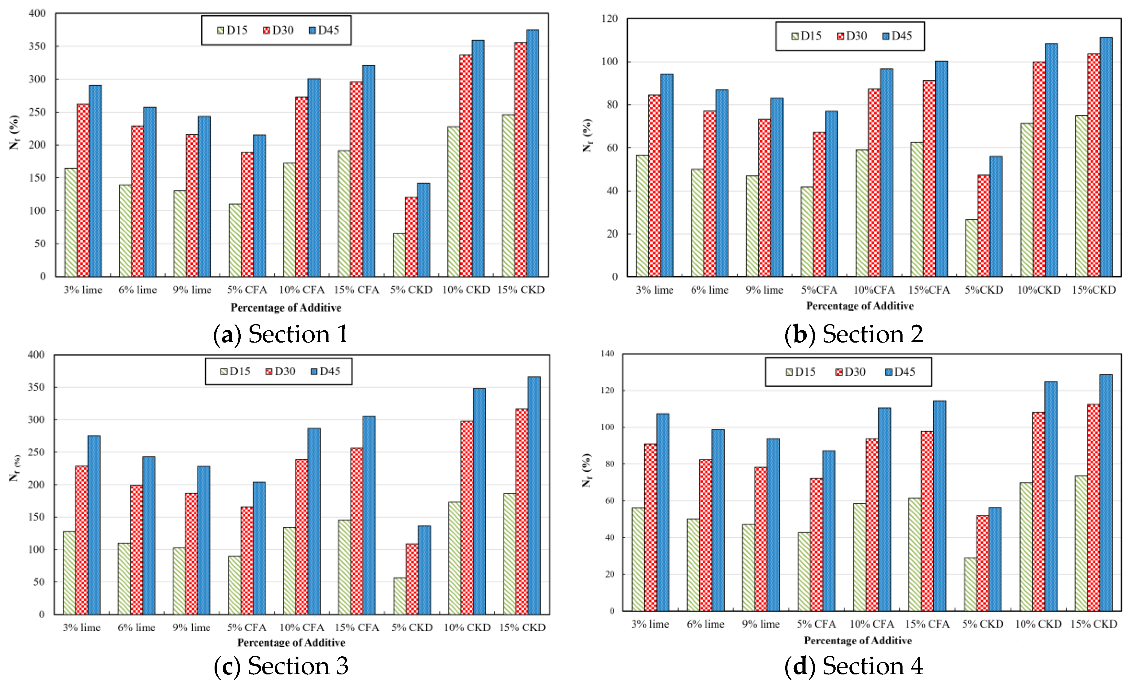
The impact of subgrade stabilization on fatigue life is a critical consideration for different pavement sections, categorized by CL and CH type subgrades. Across Sections 1–4, the observed increase in fatigue life ranges from 65% to 375%, 27% to 111%, 57% to 366%, and 29% to 129%, respectively, for CL type subgrades. In the case of CH type subgrades, the increase varies from 40% to 267%, 0% to 69%, 21% to 242%, and 20% to 112%, respectively. Notably, the highest enhancement in fatigue life occurs in the sections characterized by the lowest asphalt concrete and base thicknesses. This emphasizes that subgrade stabilization yields more pronounced life-extending benefits in thinner pavement structures with a lower load-bearing capacity.
Furthermore, the findings reveal a noteworthy relationship between the aggregate base thickness and the benefits of stabilization. Increasing the aggregate base thickness on a lime-stabilized subgrade has the potential to diminish the advantages of stabilization, showcasing a limiting impact on the increase in fatigue life. This aligns with the principles observed in an inverted pavement system, where minimizing the base thickness maximizes the load-bearing capacity of the aggregate base layer. Lowering the base thickness leads to an increase in volumetric stress within the base layer, subsequently boosting the resilient modulus of the layer [
62].
In pavements with comparable asphalt concrete thicknesses, an increase in the base layer thickness across all stabilizer percentages, stabilization thicknesses, and pavement temperatures correlates with a reduction in the percentage gain in fatigue life. This phenomenon is attributed to the decrease in the resilient modulus of the base layer as its thickness increases. For example, with 15% CKD and a stabilization thickness of 30 cm, increasing the base layer thickness from 15 to 30 cm results in a decrease in resilient modulus. In sections with an asphalt concrete layer thickness of 10 cm, the resilient modulus decreases from 269,983 to 199,655 kPa for CL subgrade soil and from 249,994 to 191,341 kPa for CH subgrade soil. Similarly, in sections with an asphalt concrete layer thickness of 15 cm, the resilient modulus decreases from 225,545 to 170,680 kPa for CL subgrade soil and from 207,662 to 163,288 kPa for CH subgrade soil. This observation underscores the applicability of the inverted pavement system concept to pavements with stabilized subgrades.
Additionally, an examination of pavements with a similar base layer thickness reveals that an increase in hot mix asphalt (HMA) layer thickness, irrespective of subgrade type, stabilizer contents, and stabilization thickness, positively impacts the percentage gain in fatigue life for the stabilized subgrade. The increase in the HMA layer’s inertial moment contributes to a decrease in tensile strains at the bottom of the asphalt layer. For instance, in a section with a 15 cm base layer thickness, 15% CKD, and 30 cm stabilization thickness, the tensile strain at the bottom of the HMA layer decreases from 189.31 to 139.37 microstrain for the CL subgrade and from 204.73 to 150.41 microstrain for the CH subgrade, when the asphalt concrete thickness increases from 10 to 15 cm. Similarly, in a section with a 30 cm base layer, the tensile strain reduces from 204.72 to 169.88 microstrain for the CL subgrade and from 248.73 to 175.76 microstrain for the CH subgrade, with the same increase in asphalt concrete thickness.
These findings align with previous research indicating that increasing the thickness of both the HMA and granular base layers results in an augmented rutting and fatigue life of pavements [
35,
63,
64]. In summary, the interplay between subgrade stabilization, asphalt concrete, and base layer thickness proves to be a multifaceted factor influencing the performance and longevity of flexible pavements.
5.2. Additive Content
5.2.1. Lime Content
For the CH subgrade, augmenting the lime content up to 6% resulted in an increase in fatigue life across all four sections, attributed to the corresponding rise in the resilient modulus of the stabilized subgrade layer. However, exceeding the 6% lime threshold had a counterproductive effect, diminishing the subgrade modulus and subsequently reducing the fatigue life. Beyond 6%, the excess lime acted as a filler material with a lower strength, leading to diminished levels of subgrade support.
Contrastingly, for the CL subgrade, the fatigue life demonstrated a decline with lime content exceeding 3%. Previous laboratory experiments on CH clay elucidated that the resilient modulus of stabilized soil initially increased with lime content from 3% to 6%, followed by a subsequent decrease. In the case of the CL subgrade, an increase in lime content beyond 3% resulted in a reduction in the resilient modulus [
55].
In the current investigation, focusing on the CL subgrade type with a stabilization thickness of 30 cm and an optimum lime content of 3%, the fatigue life witnessed substantial improvements—263%, 85%, 229%, and 91% for Sections 1–4, respectively. Similarly, for the CH subgrade with a stabilization thickness of 30 cm and an optimum lime content of 6%, the fatigue life increased by 151%, 40%, 128%, and 71% in pavement Sections 1–4, respectively. Notably, it was observed that the positive impact of lime percentage on fatigue life was more pronounced at higher stabilization thicknesses. This finding aligns with recommendations from other studies emphasizing that a stabilization thickness of at least 30 cm is optimal [
24,
65].
In summary, the influence of lime content on fatigue life varies for different subgrade types, emphasizing the need for an optimum range. While an increase in lime content initially enhances the fatigue life by improving the resilient modulus, exceeding the optimal percentage results in a decline due to reduced subgrade support. These insights underscore the importance of carefully determining the appropriate lime content, considering both subgrade type and stabilization thickness, to achieve optimal pavement performance and longevity.
5.2.2. CFA Content
For both subgrade types and in almost all cases, increasing the CFA content led to an increase in the fatigue life in all pavement sections, due to an increase in the resilient modulus of the stabilized subgrade. The only exception was observed for the CH subgrade and Section 1 which has the least thickness. For 15 cm stabilization thickness, which was the lowest stabilization thickness, pavement life decreased when increasing the CFA content from 5% to 10% due to an increase in the tensile strain at the bottom of the asphalt concrete layer. In other words, a decrease in the base layer modulus as a result of subgrade stabilization with high contents of CFA has led to an increase in and, therefore, a decrease in the fatigue life of the upper layer (i.e., asphalt course). For the case of AC10-Base15 placed on top of a CH subgrade, the resilient modulus of the base layer was 201,343, 182,215, and 191,909 kPa for 5, 10, and 15% CFA content, respectively.
For the CL subgrade, with 15% CFA applied to a depth of 30 cm, the fatigue life for Sections 1–4 improved by 296%, 91%, 257%, and 98%, respectively. For the CH subgrade, the increase in fatigue life was recorded as 90%, 22%, 77%, and 48%, respectively. It was also shown that the fatigue life improving benefits of CFA stabilization increase with an increase in the stabilization thickness.
5.2.3. CKD Content
For both subgrade types, increasing the CKD content led to an increase in the fatigue life in all pavement sections due to an increase in the resilient modulus of the stabilized subgrade. For the CL subgrade, with 15% CKD applied up to a thickness of 30 cm, the fatigue life for Sections 1–4 improved by 356%, 104%, 316%, and 112%, respectively. For the CH subgrade, the increase in fatigue life was recorded as 241%, 61%, 202%, and 96%, respectively. It was also shown that the fatigue life improving effects of CKD stabilization increase with an increase in the stabilization depth.
5.3. Stabilization Thickness
Augmenting the thickness of stabilization yielded an increase in fatigue life across all scenarios for the CL type subgrade and in the majority of instances for the CH type subgrade. However, it is noteworthy that in specific scenarios for the CH type subgrade, particularly in Sections 1 and 2 for 5% CFA and CKD, and in Section 2 for 5% and 10% CFA and 5% CKD, there was no observed enhancement in the fatigue life. This absence of improvement was attributed to a reduction in the resilient modulus of the base layer.
Within the realm of non-linear analysis, the increase in the thickness of the stabilized layer directly impacts the resilient modulus of other non-linear layers, introducing the possibility of either an increase or decrease in modulus compared to an unstabilized scenario. It is crucial to recognize that the fatigue life of a pavement system is intricately tied to the maximum tensile strain at the bottom of the asphalt concrete layer. This strain is inherently dependent on the resilient modulus of the layer beneath the asphalt concrete, typically constituted by an aggregate base layer. Therefore, an escalation in stabilization thickness might not necessarily confer benefits to the fatigue life if it results in a reduction in the resilient modulus in the base layer. This nuanced consideration underscores the importance of judiciously determining the stabilization thickness to ensure optimal pavement performance in terms of fatigue life.
For instance, in Section 1 and the CH type subgrade with 5% CFA, the resilient modulus of the aggregate base layer was estimated to be 201,343, 183,585, and 182,394 kPa for stabilization thicknesses of 15, 30, and 45 cm, respectively. The percentage improvement in fatigue life for different subgrade types, additive contents, and stabilization thicknesses is detailed in
Table 4, providing a comprehensive overview of the impact of varying parameters on pavement performance.
As shown, the increase in stabilization thickness in Sections 1 and 3, which have the lower base thicknesses, had a higher impact on improving compared with Sections 2 and 4 with higher base thicknesses. In addition, increasing the stabilization thickness from 15 cm to 45 cm has been more effective in improving the fatigue life of the CL-type subgrade compared with the CH subgrade.
6. Effect of Subgrade Stabilization on Rutting Life
The allowable number of loads to limit the rutting failure (
) for the four different sections and the two subgrade types of CL and CH without stabilization are presented in
Table 5.
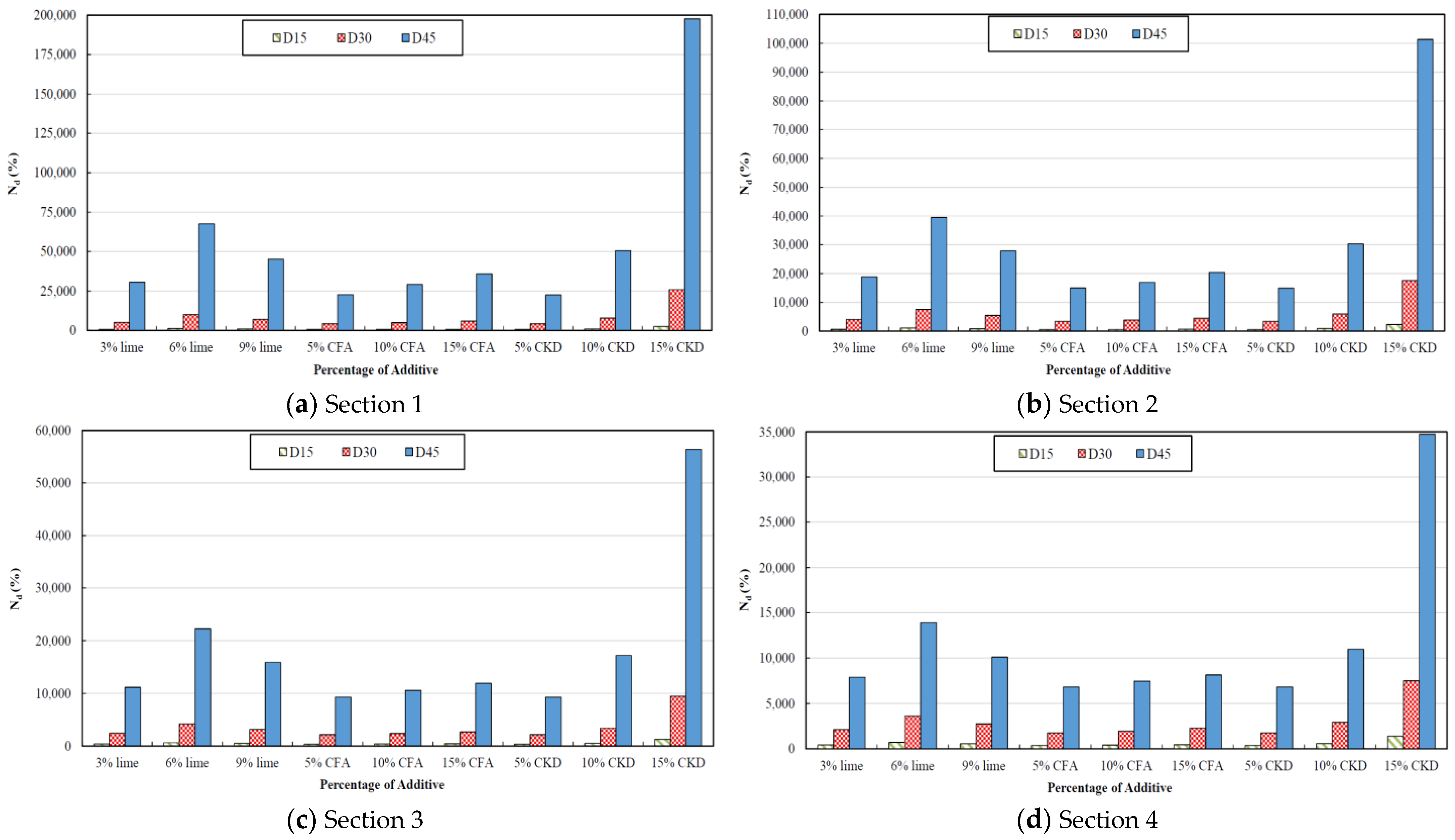
The percentage increase in rutting life due to stabilization for the subgrade soil types CL and CH for four pavement sections are presented in
Figure 7 and
Figure 8, respectively.
In the empirical rutting model shown in Equation (6), the rutting life
and the compressive strain at the top of the subgrade layer are inversely proportional. Hence, the stabilization of the subgrade would decrease the compressive strain, and this will result in an increase in the rutting life as shown in
Figure 7 and
Figure 8. The effect of various variables on the rutting life of the pavement is investigated in the following sections.
6.1. HMA and Base Layer Thickness
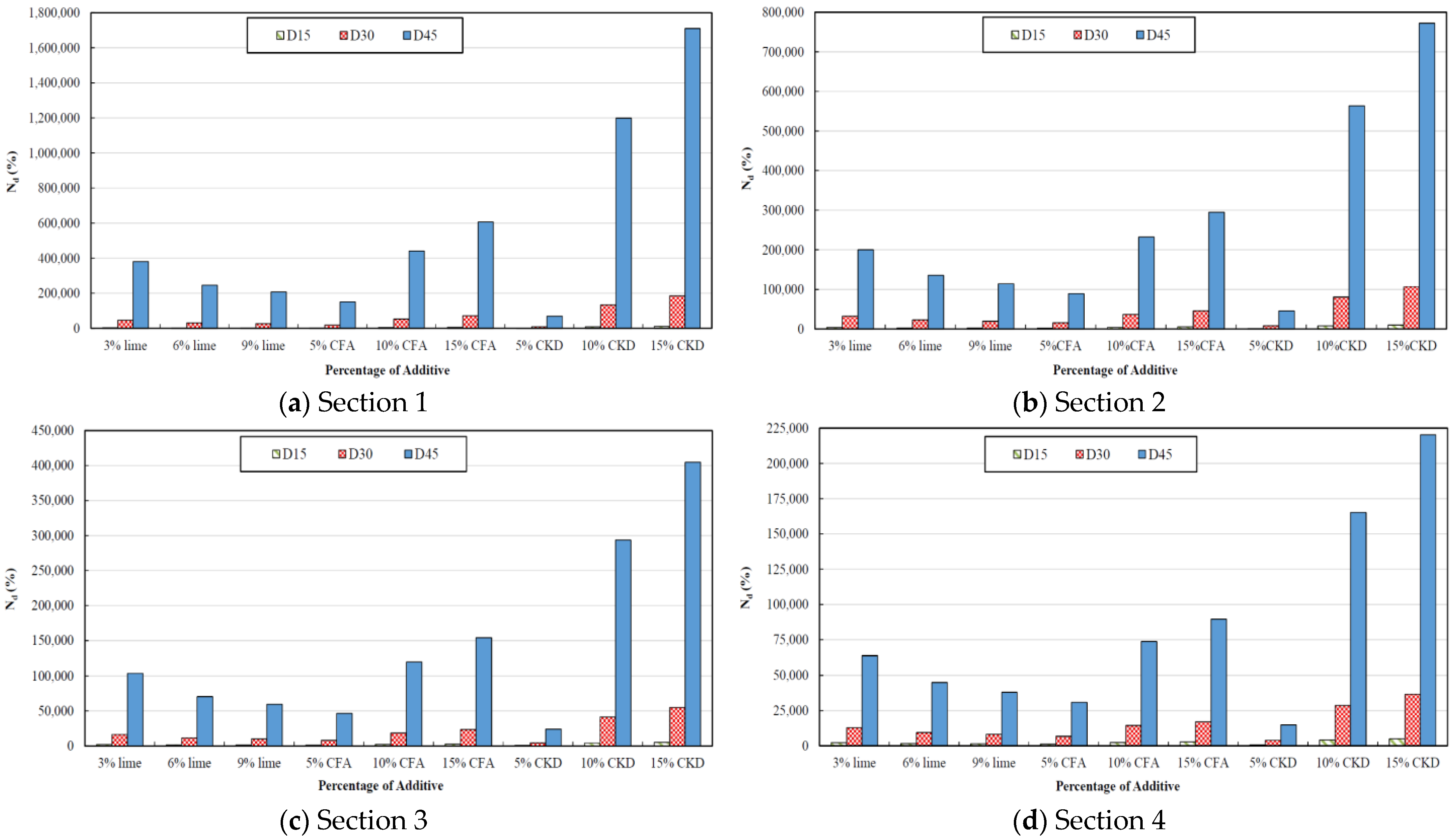
The range of rutting life improvements as a result of subgrade stabilization for Sections 1–4 are 1022%–1,709,338%, 1138%–772,137%, 660%–404,636%, and 756%–220,176%, respectively, for the CL type subgrade. For the CH subgrade, the rutting life improvements for Sections 1–4 are 570%–19,7681%, 523%–101,310%, 372%–56,397%, and 370%–34,736%, respectively. It can be observed that the highest increase in rutting life occurs in structure 1 which has the least thickness asphalt and base layers. Therefore, it can be concluded that in thinner pavement structures with a lower load-bearing capacity, subgrade stabilization is more effective in increasing the rutting life of the pavement.
6.2. Stabilizer Content
6.2.1. Lime Stabilization
The optimum lime content required to maximize the rutting life is between 3% and 6% for CL and CH type subgrades, respectively. For the CL subgrade at 30 cm stabilization depth, 3% lime stabilization of the subgrade for Sections 1–4 resulted in a 46,118%, 32,355%, 16,299%, and 12,794% increase in the rutting life of the pavement. In a similar way, for the CH subgrade at 30 cm stabilization depth, 6% lime stabilization of the subgrade for Sections 1–4 resulted in a 10,004%, 7529%, 4188%, and 3594% increase in the rutting life of the pavement.
6.2.2. CFA Stabilization
The optimum CFA content for both subgrade types is 15%. For 30 cm stabilization thickness, 15% CFA in a CL type subgrade increases the rutting life in sections 1 through 4 by 71,547%, 45,924%, 23,336%, and 17,095%, respectively, and for the CH subgrade by 5859%, 4508%, 2668%, and 2283%, respectively.
6.2.3. CKD Stabilization
The optimum CKD content for both subgrade types is 15%. For 30 cm stabilization thickness, 15% CKD in a CL type subgrade increases the rutting life in Sections 1–4 by 185,351%, 106,504%, 54,931%, and 36,511%, respectively, and for the CH subgrade by 25,888%, 17,577%, 9475%, and 7490%, respectively.
6.3. Stabilization Thickness
Increasing the stabilization thickness significantly improves the rutting life of the pavement. The percentage improvements of rutting life for optimum additive content (3% lime for the CL subgrade, 6% lime for the CH subgrade, and 15% CFA and CKD for both subgrade types) and two subgrade soil types are shown in
Table 6.
It can be observed that, in both subgrade types, increasing the stabilization thickness for pavement Section 1, which has the thinnest asphalt concrete and base layers, provides the highest increase in rutting life,
Nd, compared with the other pavement sections considered in this study. The effect of increasing the stabilization depth from 15 cm to 45 cm is more pronounced in the CL-type subgrade with lower plasticity properties compared with the CH subgrade soil. Moreover, the increase in rutting life as a result of an increase in stabilization thickness is higher when adding CKD, compared with lime and CFA. The positive effect of increasing the thickness of stabilized subgrade on increasing pavement life has been concluded by other scholars [
24,
25,
65]. It should be noted that increasing the stabilization thickness is only helpful up to a threshold thickness. Beyond this thickness, the effect on increasing the pavement life is not meaningful and, therefore, not cost-effective [
25].
7. The Fatigue Life of the Stabilized Layer
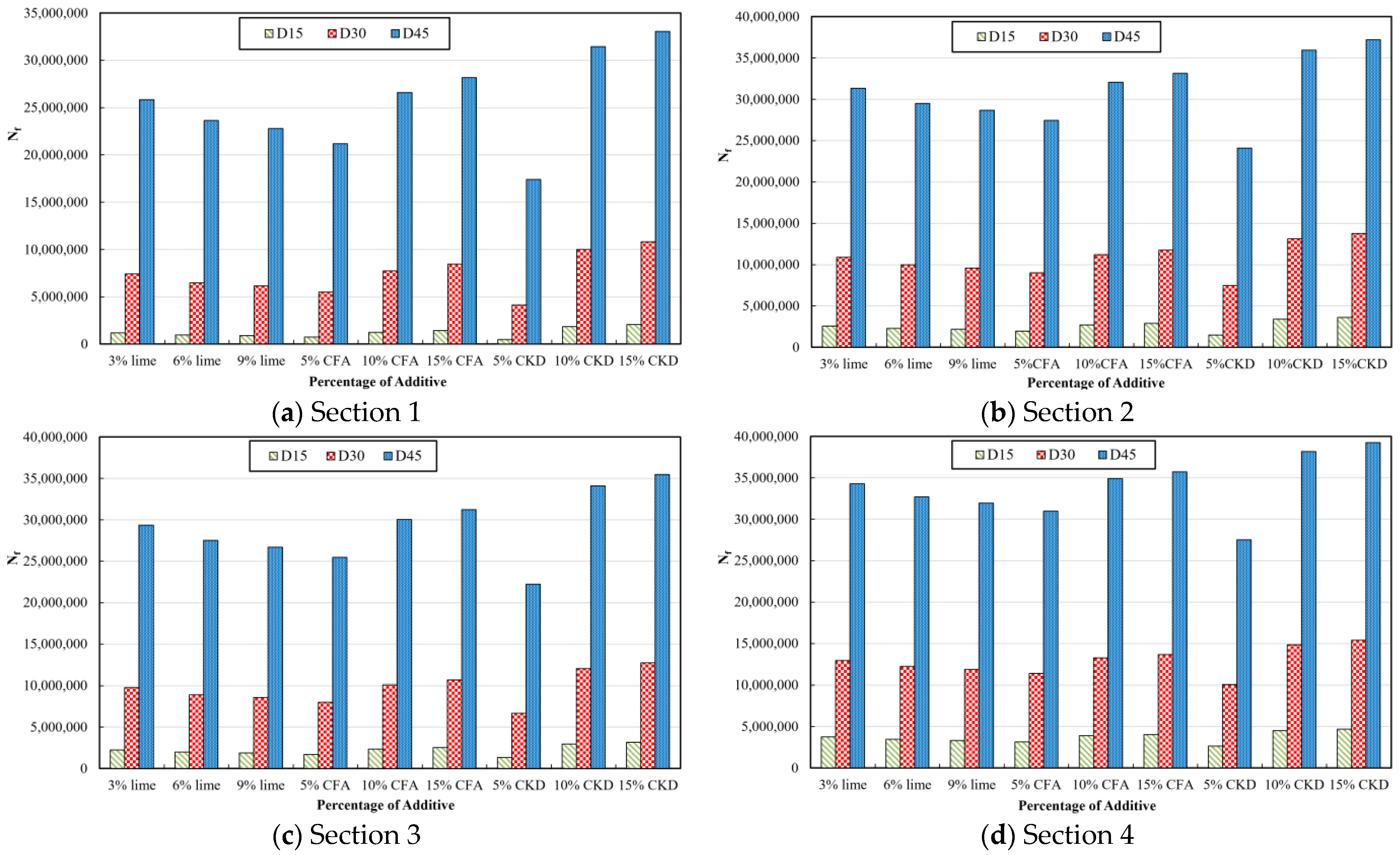
The number of load repetitions to reach fatigue failure of the stabilized layer based on the SAMDM are plotted in
Figure 9 and
Figure 10, for the four pavement sections and the two subgrade soil types of CL and CH, respectively.
According to the fatigue failure equation specified by the SAMDM, the allowable number of load repetitions to limit the fatigue failure of the stabilized subgrade layer is inversely proportional to the tensile strain at the bottom of the stabilized subgrade layer and is proportional to the thickness of the stabilized subgrade layer. Therefore, increasing the stabilization thickness of the subgrade will reduce the tensile strain (
) and significantly increases the
, as shown in
Figure 9 and
Figure 10. Consequently, it can be said that for both subgrade types, with the largest stabilization thickness (i.e., 45 cm), the fatigue life of the stabilized layer would not be the controlling factor in the pavement life calculation. Conversely, with the lowest stabilization thickness (i.e., 15 cm), the fatigue failure of the stabilized layer would occur before the fatigue failure of the asphalt concrete layer and the rutting failure of the pavement. Hence, it would be a critical factor in determining pavement life.
As shown in
Figure 9 and
Figure 10, in the majority of stabilization thicknesses (especially higher depths), the fatigue life of the stabilized subgrade layer is much higher (in particular for the CL subgrade) and is higher than the rutting life of the pavement and the fatigue life of the asphalt concrete layer. Therefore, there should be no concern about failure due to the fatigue of the stabilized layer.
The ranges of for Sections 1–4 for the CL subgrade were 488,958–33,048,452, 1,479,797–37,193,600, 1,351,998–35,454,852, and 2,628,971–39,249,407, respectively, and for the CH subgrade, the ranges were 534,280–26,152,517, 14,444,054–31,600,745, 1,449,641–29,713,106, and 2,575,685–34,509,374, respectively. Therefore, for both subgrade types, the highest of the stabilized layer was for the pavement sections with higher thicknesses (i.e., the highest thickness of the surface and base course). It can be concluded that for sections with thick base layers (i.e., Sections 2 and 4), the fatigue failure of the stabilized layer would not occur prior to the rutting and asphalt concrete fatigue failures.
8. Resilient Modulus of the Stabilized Subgrade
An increased resilient modulus of the stabilized layer is the main factor in increasing the pavement life. An additive that significantly increases the resilient modulus is likely to lead to a higher pavement life. In this section, the effect of stabilization on the modulus of the stabilized subgrade layer has been investigated. This study shows that the stabilization thickness does not have a major impact on the resilient modulus of the subgrade in the before–after stabilization scenario. Therefore,
Table 7 shows the number of times improvement in the subgrade resilient modulus after stabilization at a stabilization depth of 30 cm.
The modulus ratio (the ratio of the resilient modulus of the stabilized subgrade layer to the resilient modulus of the natural subgrade soil) shown in
Table 7 is calculated using NonPAS software after non-linear analysis for both stabilized and natural subgrades.
As shown, the increase in subgrade modulus is higher for the CL subgrade compared with the CH subgrade. The stabilization effect for a specific stabilizer is almost similar across different pavement sections. In lime stabilization, the effect of stabilization is highest at 3% lime for the CL subgrade and is highest at 6% lime for the CH subgrade. For CFA and CKD stabilization, the highest modulus ratio occurs at 15% stabilization for all four sections. Finally, the highest increase in the subgrade modulus among all additives and contents occurred at 15% CKD for all pavement sections.
9. Dominant Damage Mechanism
Table 8 shows the dominant damage mechanism, the allowable 18 kips equivalent single axle load (ESAL), and the percentage life extension across several variables such as stabilizer percentage, type of the subgrade soil, and cross-section of the pavement.
As shown, for Sections 1 and 3 before stabilization, the dominant damage mechanism for both subgrade types is rutting. However, subgrade stabilization would change the dominant damage mechanism to fatigue of the asphalt concrete layer or fatigue of the stabilized subgrade layer.
The increase in pavement life due to lime stabilization ranges from 56% to 1890% for the CL subgrade and 22% to 568% for the CH subgrade. The increase due to CFA is 62% to 2048% for the CL subgrade and 9% to 397% for the CH subgrade. For CKD stabilization, these ranges are 74% to 2323% for the CL subgrade and 39% to 797% for the CH subgrade. Therefore, the increase in pavement life with the three different additives was always higher for the CL subgrade soil compared with the CH subgrade soil.
In pavement structures 1 and 3, the fatigue life of the stabilized layer determines the pavement life (i.e., the dominant indicator) for lower stabilization thicknesses. The dominant life indicator changes into the fatigue life of the asphalt concrete layer by increasing the stabilization depth. Therefore, the thin stabilized subgrade (e.g., 15 cm) with a low base thickness on top of it, is prone to fatigue failure. Previous studies also noted that the stabilization thickness should be at least 30 cm [
24,
65]. On the other hand, regardless of the stabilization thickness, fatigue failure of the stabilized subgrade layer will not occur when having a higher thickness of base or stabilized subgrade layers. In addition, the increase in pavement life due to 15% CKD was the highest compared with the other two stabilizers in all cases.
10. Limitations and Future Directions
In this short section, the authors, despite the particularly significant findings contributing to the understanding of the behavior and improved design of flexible pavements discussed in the preceding sections—findings that will be summarized in the immediately following conclusion section—emphasize that these conclusions are valid for parameter values falling within those presented in this paper. Additionally, the authors deem it necessary, as part of their ongoing research endeavors, to further consider the behavior of different subgrade soils stabilized with other types of additives to investigate the life-extending benefits of them.
11. Conclusions
This research investigates the effect of subgrade soil stabilization on the performance and life-extension of flexible pavements. To this end, several variables affecting soil stabilization were considered, including subgrade soil type (CL or CH), additive type and content (3, 6, and 9% of hydrated lime, 5, 10, and 15% of cement kiln dust (CKD), and 5, 10, and 15% of class C fly ash (CFA)), three stabilization thicknesses (15, 30, and 45 cm), and four pavement sections with varying thicknesses. The results presented in this research may assist pavement designers and practitioners to design and construct roads that last longer. The following main conclusions can be drawn:
The results show that the advanced crushing life of the stabilized subgrade layer is usually higher than the fatigue and rutting life of the flexible pavement.
The rutting and fatigue life of pavements increased substantially when the subgrade was stabilized and the benefit of subgrade stabilization was generally more pronounced in the rutting life of the pavement, compared to the fatigue failure of asphalt concrete.
The optimum additive content that leads to the highest increase in the pavement life (i.e., fatigue life for AC and stabilized subgrade, and rutting life) occurs at 3% lime for the CL subgrade type, 6% lime for the CH subgrade type, and 15% CKD and CFA for both subgrade types. The highest increase in pavement life is estimated for 15% CKD application.
According to the optimum usage of additives to stabilize subgrade soils, the range of life increase for 3% of lime stabilization would be from 56% to 1890% for the CL type subgrade, and for 6% of lime in a CH type subgrade the life increase estimate is 22% to 568%. For stabilization using 15% of CFA, the increase is estimated to be from 62% to 2048% in a CL subgrade, and from 9% to 397% for a CH subgrade. Using 15% of CKD, the increase is estimated to be from 74% to 2323% in a CL subgrade, and from 39% to 797% for a CH-type subgrade.
It was observed that in almost all cases, the increase in the stabilization thickness would lead to an increase in the fatigue life of the asphalt concrete and stabilized layers and also the rutting life of the pavement. Therefore, it can be concluded that the increase in stabilization thickness would increase the stabilization effectiveness. The impact of increasing stabilization thickness is more pronounced in increasing the rutting life and fatigue life of the stabilized layer, compared with the fatigue life of the asphalt concrete layer.
For different pavement structures, the stabilization thickness increase was more effective for Sections 1 and 3 with thinner base layers, compared with Sections 2 and 4 which have thicker base layers. In addition, the rutting life improvement as a result of stabilization on Section 1, which had the lowest thickness of asphalt concrete and base layers, was the highest among other cases.
The fatigue and rutting life of the pavement was higher for the CH soil type subgrade due to its higher resilient modulus. Stabilization was more effective in the CL subgrade type when comparing the benefit in pavement life before and after stabilization.
In pavement sections with thinner aggregate bases (i.e., Sections 1 and 3), the fatigue of the stabilized layer is the dominant distress mode for lower stabilization thicknesses (i.e., less than 30 cm). The dominant distress mode changes to fatigue of the asphalt concrete layer by increasing the stabilization thickness. Therefore, for pavements with thin base courses, a lower stabilization thickness can lead to the fatigue distress of the stabilized layer.


 ,
, 


