Abstract
This study presents an initial feasibility concept paper for a proposed crosstie system, an innovative railroad crosstie reinforcement system designed to reduce the stresses transmitted to the underlying ballast. While not developed for a specific industry client, the proposed crosstie system lays the groundwork for patent application and potential commercialization, offering a novel alternative to conventional railroad construction. Finite Element Analysis demonstrated that this system can reduce effective stress on the ballast by up to 24%, effectively making train loads appear lighter to the substructure. The design of the proposed system focuses on mitigating the excessive stresses transmitted from crossties to the ballast layer in heavy axle load (HAL) freight rail operations. The goal was to create a reinforcement mechanism that is modular, compatible with existing track infrastructure, and capable of reducing maintenance costs by distributing loads more effectively across the ballast and subgrade. The findings indicate that this system is not only the most cost-effective and sustainable solution but also holds promise for reducing fixed stock investment, minimizing downtime for track maintenance, and enabling expanded rail network connectivity. These results support continued research and investment in the system’s development and deployment.
1. Introduction
Railroads efficiently transport goods and passengers along established routes but have significant initial and maintenance costs associated with track and railbed infrastructure (also called fixed stock). Given the importance of environmental and economic efficiency, engineers are obligated to reduce costs in any way they can to reduce the impact of heavy industry on the natural world while also saving their clients’ money. A significant contributor to the costs of railroads is the enormous dynamic and cyclic load that must be diffused from the wheel, through the track, across the subgrade, and finally into the surrounding native soil [,,].
The proposed crosstie system (Figure 1) reduces the cost and environmental impact by making better use of existing track structure and subgrade. This product does so by spreading the applied load of a typical track-wheel loading scenario across many ties, spreading the peak wheel loads over a longer length of track, and reducing the magnitude of stress conveyed to the ballast under the crossties.
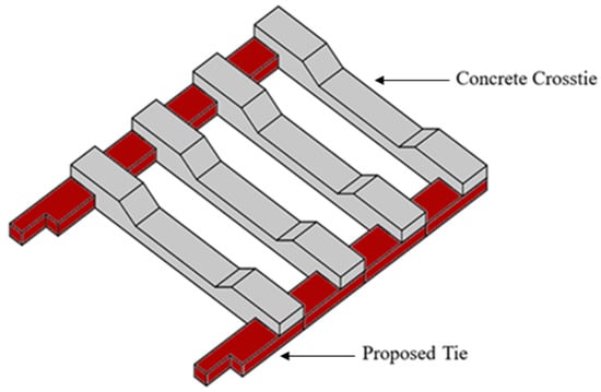
Figure 1.
Proposed Tie system configuration. The tessellating tiles distribute loads across larger ballast areas.
This technique allows railroads to save money in reduced excavation for track structure and subgrade improvement, easier remediation of heaving, and more route options by enabling freight routes to be constructed in what are considered “less ideal” soils. Under high-stress cyclic loading, cohesive soils will tend to flow away from the centerline, as shown in Figure 2. At the onset of instability (Figure 2a), a localized zone of remolded clay forms within the clay subgrade, indicating the initiation of shear failure. With continued deformation, this instability propagates upward, resulting in surface manifestation in the form of heave (Figure 2b). At this stage, the displaced remolded clay pushes the track substructure upward, causing significant distortion and potential serviceability issues []. This sequence highlights how subgrade failure in cohesive soils transitions from a hidden internal mechanism to a visible surface deformation that compromises track stability. The void left behind by the heave weakens the track, requiring increased maintenance costs or a “go-slow” order on the track, reducing commercial throughput. The objective of this research is to provide an initial feasibility assessment for the New-Tie system that will reduce the maximum stress transmitted from crosstie to ballast, saving railroad companies money and reducing the impact on the surrounding environment.
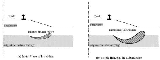
Figure 2.
Heaving, visualized.
New-Tie can be used in place of traditional crossties to reduce the stress applied to the existing ballast, thereby bringing a high-risk system into acceptable tolerances. By reducing the maintenance impact of heaving remediation from total replacement of subgrade to a simple crosstie replacement, New-Tie will save railroad operators money by eliminating the need for costly changes in operations, allowing necessary maintenance to be performed faster and with less heavy equipment than currently required. Regular, non-heaving maintenance cycles are driven by the rate of ballast fouling. No matter how tough ballast rock is, eventually enough will be down to fill up the spaces between rocks (fouling). Losing the air voids between rocks reduces track drainage and decreases the layer’s elasticity, causing more force to be transmitted into the subgrade beneath. By reducing the peak loads transmitted into and through the ballast layer, New-Tie installation will reduce the need for the frequency of maintenance from regular rail operations.
2. Methodology
The present research presents an initial feasibility concept analysis for a novel railroad crosstie system (New-Tie) that reduces the environmental and economic costs of railroads. A numerical model simulation using Finite Element Analysis (FEA) is conducted to compare the difference in the stress and displacement in both the ballast layer and subgrade. The results of this analysis determine the magnitude of benefit for construction with New-Tie. The remainder of the research is a case study of track remediation in the Black Rock Desert of Northern Nevada. This case study indicates the relative economic viability of the New-Tie system compared to other typical alternatives. All design parameters were cross-referenced with the AREMA Manual for Railway Engineering to ensure code compliance []. Subgrade strength parameters and train-track load assumptions were validated using published soil data.
2.1. Materials and Geometries
A comprehensive list of terms to use as a glossary for the analysis is presented in Table 1. Typical rail, tie, and fastener, granular and subgrade layer, and wheel load parameters were utilized to determine a baseline for deviator stress analyses used to compare a system with and without New-Tie. The input parameters for the track design include the properties of the rails, ties, fasteners, ballast, and subgrade, along with the applied wheel load. The rail is defined by its elastic modulus (E = 207 GPa), moment of inertia (I = 3.95 × 10⁻⁶ m4), cross-sectional area (8.61 × 10⁻³ m2), gauge (1.5 m, distance between two rails), and mass per unit length (68 kg/m). The tie and fastener system is characterized by a base width of 0.273 m, base length of 2.6 m, cross-sectional area of 5.6 × 10⁻² m2, elastic modulus of 31 GPa, moment of inertia of 2.42 × 10⁻⁴ m4, tie mass of 363 kg, and spacing of 0.61 m, with the fastening system providing a stiffness of 175 kN/mm. The granular ballast layer is represented by a density of 1.76 Mg/m3, Poisson’s ratio of 0.3, and modulus of 280 MPa, while the subgrade layer has a density of 1.92 Mg/m3, Poisson’s ratio of 0.35, modulus of 55 MPa, and an at-rest earth pressure coefficient (K0) of 1.0. Finally, the wheel load is applied vertically with a magnitude of 230 kN, representing the axle load of a heavy freight train.

Table 1.
Parameters used for Comparative Roadbed Analysis [,,].
Figure 3, “Railroad Tie”, defines the railroad crosstie to be used in the presented research. The material properties for the crosstie are listed in Table 1.
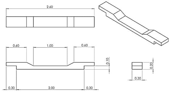
Figure 3.
Original concrete crosstie (units are in meters).
Figure 4, “New-Tie,” defines the proposed cross-tie modification. The dimensions of the New-Tie were selected to have the same width and material properties as the original crosstie. Consistent width of New-Tie and crossties improves constructability by enabling installation and maintenance with existing equipment. The elongated ‘Z’ shape of the New-Tie allows for even overlap with the crosstie that rests on top, as shown in the “Assembly” drawing.
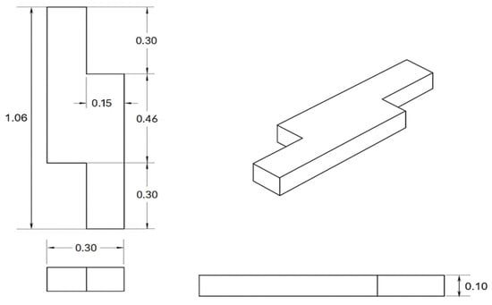
Figure 4.
Proposed “New-Tie” geometry (units are in meters).
Figure 5, “Assembly,” shows the arrangement of New-Tie and crosstie. This drawing shows four New-Ties in contact with each crosstie, allowing for maximum stress dissipation from each crosstie through the New-Tie into the ballast. This configuration was intended not only to provide additional rigidity between adjacent crossties but also to allow for greater surface area for the axle load to be transferred into the ballast.
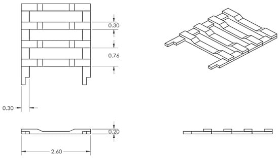
Figure 5.
Proposed “New-Tie” system assembly (units are in meters).
2.2. Numerical Modeling
Comparative analysis of stress and displacement in ballast and subgrade soil lays the groundwork for this research. The FEA will use a selected set of soil, ballast, rail, and crosstie parameters to determine the general difference between standard crossties and the New-Tie system when loaded with a single axle load. It is noted that the assumptions and model setup are not a perfect representation of reality; however, this analysis is meant to indicate whether further analysis and investment are warranted for this technology, not to give functional design parameters. The general design of the New-Tie system was developed through several iterations based on preliminary model results. The location and geometry of the new crosstie system are adjusted to improve results, but material properties are kept constant, and the fine design of the crosstie-New-Tie interface is considered beyond gravity. This analysis will also only be valid for vertical loading on a straight, level track to simplify the inputs to the model and the generated results. The FEA model did not include dynamic loading, lateral forces, or cyclic fatigue effects and assumed idealized material behavior.
Figure 6 demonstrates the existing condition of the conventional ballast and crosstie system used in freight railroad operations and the proposed New-Tie system, showing the configuration of rails, crossties, ballast, and subgrade layer used in FEA modeling. The model consists of rails, ties, ballast, and subgrade, discretized using three-dimensional, eight-node reduced integration solid elements (C3D8R). The boundary conditions were applied such that the bottom of the subgrade was fully constrained in all three directions (X, Y, and Z), representing a fixed support condition. The vertical sides of the model were restrained in the X and Y to prevent lateral movement, while remaining free in the vertical direction (Z) to allow settlement. The ties were connected to the underlying soil through a hard contact interaction to ensure realistic load transfer, while the rail was rigidly fixed to the ties to simulate the fastening system. This formulation prevents any penetration between the contacting surfaces and allows the transfer of compressive stresses only, ensuring a realistic representation of the rail–soil interface. The penalty enforcement method was adopted as the default approach, allowing minimal numerical penetration while maintaining solution stability. The rail was assigned as the major surface due to its higher stiffness, and the soil as the minor surface. This contact definition effectively simulates the support and load transfer mechanism between the rail and the underlying soil.
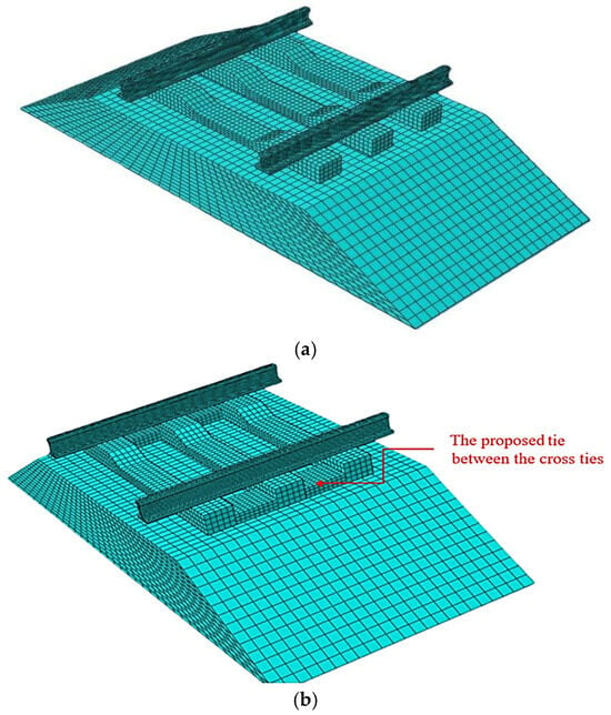
Figure 6.
FEA model of (a) standard freight railbed and (b) proposed New-Tie system.
3. Numerical Modeling Results
The two models, including the original crosstie and the proposed New-Tie, were run in a stress analysis finite element software. For the original crosstie, Figure 7a shows the stress at the crosstie–ballast interface with a maximum compression value in dark blue of 1.094 MPa and a general ballast stress in orange of 45.1 KPa. Figure 8a shows the displacement at the crosstie–ballast interface with a maximum compression of 1.233 mm, represented by the dark blue color. Figure 7b shows the stress at the crosstie–ballast interface with a maximum compression value in dark blue of 1.018 MPa. Figure 8b shows the displacement at the crosstie–ballast interface with a maximum compression of 1.090 mm, represented by the dark blue color.
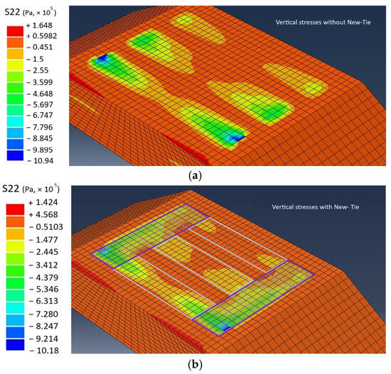
Figure 7.
Model of vertical stress at ballast–crosstie interface (a) without New-Tie and (b) with New-Tie.
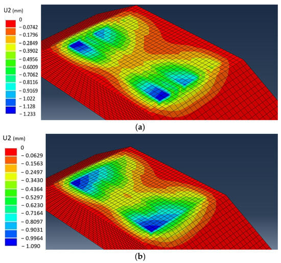
Figure 8.
Model of vertical displacement at ballast–crosstie Interface (a) without New-Tie and (b) with New-Tie.
The crosstie and New-Tie were modeled using the same very stiff material, which resulted in significant load transmitted directly through the crosstie into the ballast, with relatively less spread through the New-Tie. Additional research and modeling are warranted to determine whether a reduction in the stiffness (and therefore cost) of the crosstie relative to the New-Tie would provide acceptable performance while also further improving the performance of the stress-dissipation effect of the New-Tie. This could enable wood or composite crossties to be used with concrete New-Tie or other material optimizations to reduce cost. The nearly 24% reduction in stress in the ballast shown in Table 2 was significant, indicating improved load distribution and long-term ballast and subgrade durability. This is due to the fact that stress, defined as force over area, is spread over a substantial area in the ballast. Table 2 summarizes the change in ballast values between the two models.

Table 2.
Comparative model heaving values.
When this stress in the ballast was reduced, this reduced the chance of deformation and fouling, increasing the lifespan of the track. The reduction in stress in terms of the maximum values was calculated as roughly 15%. This was substantial when considering that a reduction in stress overall leads to longer service life and reduced maintenance cycles. Table 3 shows the change in maximum magnitude values.

Table 3.
Comparative model maximum magnitude values.
Although the change in maximum deflection was small (around 0.2 mm), any reduction in the magnitude of cyclic loading of the ballast granite could have a significant impact on the fatigue and overall life cycle of the ballast. For the sake of brevity, this report focuses on the change in maximum stress and leaves the analysis of cyclic loading to further research.
Change in ballast stress is summarized by Figure 9, which shows the stress profile across the midline of the crosstie with and without New-Tie. This plot shows the greatest reduction is at the ends of the crosstie, where the snowshoe effect of the New-Tie is the greatest. Figure 9 illustrates the distribution of vertical stress beneath the rail tie with and without the proposed New-Tie system. The results show that the inclusion of the proposed Tie leads to a more uniform stress distribution across the tie width. In the case without the proposed Tie, the stress is concentrated near the tie edges, indicating higher local deformation in the subgrade. When the New-Tie system is used, these edge concentrations are reduced, and the peak stress shifts slightly toward the center, demonstrating improved load dispersion and a more stable contact condition between the tie and the supporting soil. This indicates that the proposed system enhances the stress transfer mechanism and can potentially reduce localized settlement under repeated train loads.
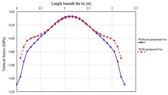
Figure 9.
Comparison of vertical stress beneath the crosstie centerline.
Since ballast remediation may still be performed easily with the New-Tie system, as they were designed to be modular and easily installable and removable. With New-Tie, the decreases in the magnitude of stress and deflection would lead to a reduction in maintenance cycles and increase serviceability. The decreases in stresses and deflections in the ballast layer would increase the structural integrity of the system overall.
4. Case Study Design Criteria
The present study considers the viability of the New-Tie system by comparing the most promising alternatives (slab track and geotechnical improvement) with the New-Tie system. The chosen case study area was the Black Rock Desert, just east of Gerlach, Nevada (Figure 10). This site was chosen due to its silty sand, which is typically considered to be unfit for railroad construction. Despite this soft soil, a Union Pacific freight line runs just south of Burning Man, within the endorheic basin that encompasses it. This 3 km stretch of rail line was selected based on three key factors. First, the site is underlain by soft soil with characteristics that typically demand significant subgrade improvements and pose the highest risk of heaving among soils in Nevada. Second, the location already contains an existing rail line, making it suitable for evaluation and comparison. Finally, the rail alignment is flat and straight, providing consistent conditions for analysis.
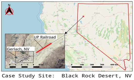
Figure 10.
An outline of the selected site in the Black Rock Desert, NV.
Three kilometers was chosen as the length of analysis because of the relative “flatness” of this section of the rail line within the Black Rock Desert. This “flatness” was crucial to compare alternatives based on the differences between New-Tie and the two chosen alternatives of subgrade improvement and slab track construction, without accounting for slope and superelevation improvements.
The classification of the soil of the Black Rock Desert site was determined from UC Davis’ California Soil Resource Soil Web application []. This interactive map provided the Black Rock Desert’s United States Classification System soil classification of SM—Typic Udorthents, which is a fine-grained, silty sand-type soil. The bearing capacity of typic udorthents decreases by 25% when moist []; however, due to the comparative nature of this case study, no accommodations were made for the moisture content of the soil. With this classification, typical soil characteristic values were determined (as necessary for the analysis of “typical” soil for railroad construction). Table 4 presents the mechanical properties of the existing subgrade in the area of the case study.

Table 4.
Subgrade layer in the Black Rock Desert (for case study) [].
The three design alternatives considered in this case study are geotechnical improvement, replacement of the existing track with slab track, and installation of New-Tie.
With these characteristics of the soil determined and the volumes of necessary materials required, a comparison between New-Tai and the alternative improvements of subgrade improvements and slab track construction was made. All models were performed considering the same load of 333 kN. The major differences between the analysis of New-Tie, subgrade improvements, and slab track inclusion were the geometric and material properties of the slab track and the geometry, or increased depth, of the subgrade improvements.
4.1. Geotechnical Improvement of Existing Soil
This design alternative consists of removing the existing track and improving the ballast and soil layers so that the stress transmitted to the subgrade is within an acceptable 3-factor of safety of the bearing capacity of 25 psi []. The existing track must be removed, and the subgrade excavated and compacted to a depth of 1.2 m. Crossties were replaced with prestressed concrete crossties for consistency with the New-Tie alternative. All installation was performed according to standard rail construction procedures. Table 5 shows the designed subgrade improvement for the case study.

Table 5.
Excavation volumes for the case study.
4.2. Replacement with Slab Track
This design alternative consists of removing the existing track and excavating the subgrade to install the underlayment and formwork required for slab track. The subgrade was excavated to a depth of 1.2 m with a section width of 5.18 m. The underlayment for the slab track was 0.15 m of granite [,,]. Table 6 shows the computed dimensions and volume for the slab track for the case study.

Table 6.
Slab track volume computations.
This gives a total concrete volume for slab-track construction of 4024 m3.
4.3. Installation of New-Tie
This design alternative preserved the rail and replaced the crossties and 0.19 m of ballast depth so that the top of the rail elevation was preserved. The New-Tie system was installed on top of the ballast layer according to standard rail construction procedures.
The volumes of materials required for the construction of suitable alternatives were determined from the geometries of each improvement. The slab track volumes were determined from the standard width, depth, and length of the case study, 3 km. It is important to note, however, that the case study length of 3 km was not divisible evenly by the standard slab section length of 4.96 m, so a total length of 3000 m was required for slab-track construction. For subgrade improvements, the material properties of the Black Rock Desert site were used to determine the subgrade excavation depth, as the purpose of subgrade improvements is to “fix” the existing soil by an increased depth of compaction or outright soil replacement.
Figure 11 and Figure 12 show the dimension reduction cross-section of the railroad by using the New-Tie system versus subgrade improvement.

Figure 11.
Cross-section of the railroad with the New-Tie system.
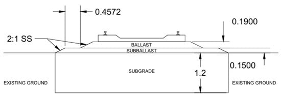
Figure 12.
Cross-section of the railroad with subgrade improvement.
4.4. Performance and Economic Evaluation
The New-Tie System not only reduces costs but also enhances performance. It decreases the maximum displacement of concrete crossties by 12% and reduces ballast displacement by 2%. In terms of stresses, the system lowers the maximum vertical stress by 7% and ballast stress by 24%.
Environmentally, the system reduces the overall carbon footprint of granular layer reinforcement in railroads. While the exact reductions in deflection, stress, maintenance cycles, construction cost, and environmental impact may vary depending on site-specific material properties and layouts, the case study conducted in the Black Rock Desert, Nevada, demonstrates consistent benefits. The results confirm that neither construction nor maintenance parameters are negatively impacted, even in soft soils with low bearing capacity.
For these reasons, further research is recommended to test different crosstie and New-Tie materials, as well as to optimize designs for curved track sections and turnouts, where stress and deflection behavior differ from straight alignments. Overall, the New-Tie System provides a practical and innovative middle ground between subgrade replacement and slab track construction and presents a strong candidate for broader industry implementation.
5. Conclusions
This study presented an initial feasibility concept assessment of the New-Tie system as an innovative reinforcement method for railroad crossties. Through finite element modeling and a comparative case study, the system was assessed against conventional alternatives, including subgrade improvement and slab track construction. The findings demonstrate that New-Tie not only reduces stresses and displacements in the ballast layer but also offers potential economic and environmental benefits. The conclusions of this research are summarized as follows:
- The New-Tie System effectively reduces stresses transmitted to the ballast, achieving up to a 24% reduction in ballast stress and lowering crosstie displacement by 12%.
- Finite Element Analysis confirmed that stress distribution in the ballast is improved, leading to greater track durability and extended maintenance cycles.
- The case study in the Black Rock Desert, Nevada, demonstrated that New-Tie is suitable for both “standard” soils and softer soils with low bearing capacity, without negatively impacting performance.
- Environmentally, the system contributes to a reduced carbon footprint by minimizing the need for extensive subgrade replacement or large-scale concrete use.
- The New-Tie system represents a practical middle ground between subgrade replacement and slab track construction, offering an efficient solution that enhances load distribution while maintaining ease of installation and adaptability for existing railway infrastructures.
- Further research is recommended to test different materials and geometries for New-Ties and crossties, especially in curved track sections and turnouts, to optimize performance under diverse loading conditions.
Author Contributions
Conceptualization, M.K. (Moses Karakouzian); methodology, M.K. (Moses Karakouzian), M.C., W.V.V., P.W. and M.K. (Mehrdad Karami); software, M.K. (Mehrdad Karami); writing—original draft preparation, M.C., W.V.V. and P.W.; writing—review and editing, M.K. (Moses Karakouzian) and M.K. (Mehrdad Karami); supervision, M.K. (Moses Karakouzian). All authors have read and agreed to the published version of the manuscript.
Funding
This research received no external funding.
Data Availability Statement
The raw data supporting the conclusions of this article will be made available by the authors on request.
Conflicts of Interest
The authors declare no conflict of interest.
References
- Li, D.; Selig, E.T. Method for railroad track foundation design. I: Development. J. Geotech. Geoenviron. Eng. 1998, 124, 316–322. [Google Scholar] [CrossRef]
- Wang, Y.; Dimitrovová, Z.; Yau, J.D. Dynamic responses of vehicle ballasted track interaction system for heavy haul trains. In MATEC Web of Conferences; EDP Sciences: London, UK, 2018; Volume 148, p. 05004. [Google Scholar]
- Selig, E.; Waters, J. Track Geotechnology and Substructure Management; Thomas Telford Publications: London, UK, 1994. [Google Scholar]
- Sussmann, T.R.; Hyslip, J.P. Track Substructure Design Methodology and Data. In Proceedings of the Joint Rail Conference, Urbana, IL, USA, 27–29 April 2010; Volume 49064, pp. 369–376. [Google Scholar]
- Manual of Railroad Engineering Ch 1 (Version 2014); American Railway Engineering and Maintenance-of-Way Association: Lanham, MD, USA, 2014.
- Tutumluer, E.; Dombrow, W.; Huang, H. Laboratory characterization of coal dust fouled ballast behavior. In Proceedings of the AREMA 2008 Annual Conference & Exposition, Salt Lake City, UT, USA, 21–24 September 2008; pp. 21–24. [Google Scholar]
- SoilWeb: An Online Soil Survey Browser|California Soil Resource Lab. (n.d.). Available online: https://casoilresource.lawr.ucdavis.edu/gmap/ (accessed on 4 April 2025).
- Kererat, C. Bearing capacity determination of sandy soil layer using light weight penetration test. J. Appl. Eng. Sci. 2016, 14, 290–295. [Google Scholar] [CrossRef]
- Cheng, W.C.; Li, G.; Zhou, A.; Xu, J. Rethinking the water leak incident of tunnel Luo09 to prepare for a challenging future. Adv. Civ. Eng. 2019, 2019, 4695987. [Google Scholar] [CrossRef]
- Li, D.; Selig, E.T. Evaluation of railway subgrade problems. Transp. Res. Rec. 1995, 1489, 17. [Google Scholar]
- Luo, J.; Zhu, S.; Zhai, W. An advanced train-slab track spatially coupled dynamics model: Theoretical methodologies and numerical applications. J. Sound Vib. 2021, 501, 116059. [Google Scholar] [CrossRef]
- Ye, Q.; Luo, Q.; Feng, G.; Wang, T.; Xie, H. Stress distribution in roadbeds of slab tracks with longitudinal discontinuities. Railw. Eng. Sci. 2023, 31, 61–74. [Google Scholar] [CrossRef]
- Gao, Z.; Dersch, M.S.; Qian, Y.; Csenge, M.V.; Edwards, J.R. Use of ballast support condition back-calculator for quantification of ballast pressure distribution under concrete sleepers. In Bearing Capacity of Roads, Railways and Airfields; CRC Press: Boca Raton, FL, USA, 2017; pp. 1955–1960. [Google Scholar]
Disclaimer/Publisher’s Note: The statements, opinions and data contained in all publications are solely those of the individual author(s) and contributor(s) and not of MDPI and/or the editor(s). MDPI and/or the editor(s) disclaim responsibility for any injury to people or property resulting from any ideas, methods, instructions or products referred to in the content. |
© 2025 by the authors. Licensee MDPI, Basel, Switzerland. This article is an open access article distributed under the terms and conditions of the Creative Commons Attribution (CC BY) license (https://creativecommons.org/licenses/by/4.0/).