Article

Design and Prototype of L-CADEL.v5 Elbow Assisting Device

Department of Industrial Engineering, University of Rome Tor Vergata, Via del Politecnico 1, 00133 Rome, Italy
*
Author to whom correspondence should be addressed.
Designs 2025, 9(6), 126; https://doi.org/10.3390/designs9060126 (registering DOI)
Submission received: 14 September 2025 / Revised: 31 October 2025 / Accepted: 6 November 2025 / Published: 11 November 2025
(This article belongs to the Section Bioengineering Design)

Abstract

A new version of the L-CADEL elbow joint assisting device is presented as version v5. The design is revised based on the experience of previous versions and on the requirements that consider the application for physical exercise for the elderly people at home. A laboratory prototype has been created with lightweight, portable and easy-to-use functionality that is confirmed by lab test results. A web interface was developed to manage the device as well as to acquire and elaborate data. Results of lab tests are discussed to validate the design feasibility and to characterize the operation performance for future clinical assessments.

1. Introduction

The elbow joint [1] is one of the key elements of the musculoskeletal system. It provides opportunities for nutrition, hygiene, actions and control of everyday tasks. Diseases of elderly people can lead to degeneration of the muscular control system and disruption of the movement pattern of the limbs, particularly the elbow joint [2,3]. This problem is common among elderly people, patients with neurological disorders, people suffering from long-term diseases or people who have experienced traumatic events [4]. Thus, the loss of mobility of the elbow joint deprives a person of some independence and reduces their quality of life. The causes can be different: injuries, stroke or chronic inflammation, as pointed out in [5,6,7,8]. Congenital conditions such as cerebral palsy, radio-ulnar synostosis, radial head dislocation, ankylosis and muscular dystrophy [9,10] can also be the cause. All these diseases damage the muscles that control movements and have a severe impact on the musculoskeletal system.
Physiotherapy based on repetitive exercises [11] helps to restore control and motor function of the body. It has proven its effectiveness in improving motor functions, flexibility and strength [12]. In addition, it helps to reduce pain, improves mood and activates the neuroplasticity process, the ability of the brain to rebuild and learn new movements [13,14,15]. However, traditional therapy requires frequent visits to a physiotherapist. It also requires patience, time and money from the patient. All this can lead the patient to risk losing motivation [16,17]. Modern technologies can be the answer [18]: robotic, and especially cable-driven, assisting devices facilitate recovery, allowing patients to do a course of exercises at home [19,20]. They are safe, compact, convenient and can accurately dose the load, which makes them especially useful for elderly people and people with limited mobility. Physiotherapists can monitor the results of patients’ exercise performance online through applications, adjusting the course of recovery. This will reduce the workload of physiotherapists, allowing them to see more patients daily and focus on more complex cases. For patients, such assistive devices can facilitate the recovery process and make it convenient at home and affordable physiologically and financially [20].
The first devices of this kind were bulky and expensive, which limited their use [21]. But new generations of systems are becoming lighter, more accessible and more user-oriented [22]. Cable-driven solutions are of particular interest [23,24]. Their use reduces the rehabilitation time of the injured joint. Their compact size increases convenience for the user and allows the user to perform exercises at home [25,26]. The simplicity of the design allows patients to use the device independently, without additional assistance. The presence of feedback allows physiotherapists to receive the results of the user’s exercise online through remote monitoring. Automatic data acquisition and data elaboration, as well as their storage in an external database for post-processing, increases accuracy and efficiency [27,28]. One of the promising cable-driven assisting devices is L-CADEL [29,30,31,32]. The prototype was designed based on previous versions [29,30,31,32]. Ergonomic features were improved; the design was made lighter and more adaptable to the user’s capabilities. Testing of the prototype in laboratory conditions showed its advantages and disadvantages [31]. It includes sensors for monitoring movement, muscle activity and load, which increases the efficiency and safety of use.
This paper describes a new version, L-CADEL v5, of the elbow-assisting device, based on previous versions and focused on motion assistance of the elbow joint of elderly people. Each part is designed based on the user’s characteristics. The organic and lightweight design allows for increased convenience for users with the ability to use the device without additional assistance. The added display allows the user to monitor information about all elements of the system and allows the user to control the device. The added web interface allows a user to receive data in real time and save data to an external database. The added interface for physiotherapists allows them to receive data from experiments in a user-friendly graphical format and save the results in various formats. All these components are designed to use the device as a reliable, lightweight, accessible and convenient motion assisting tool, capable of maintaining autonomy and improving the quality of life of elderly people without the constant presence of a physiotherapist [27,33].
The aim of the paper is to present the design of L-CADELv5 and the proof-of-concept of its feasibility in assisting the elbow motion with better capabilities and performance than previous versions.

2. Materials and Methods

This section presents the basic requirements for the design of the assisting device, based on the device platforms with associated elements. A 3D printer with PLA material is used for printing structure parts. The use of commercial components allows us to reduce the cost of the device and to quickly replace elements if necessary.

2.1. Design Requirements

The new version of the L-CADEL v5 is designed mainly for elderly people. It can also be used for rehabilitation exercises to restore joint mobility. This assisting device allows a user to exercise daily at home, with minimal involvement of a physiotherapist or medical staff. The main requirements in the development of the new elbow-assisting device referenced in Figure 1 are as follows:
  • Weight. For comfortable and portable use, the device should be lightweight—less than 1 kg. The device should contain only the necessary elements with user-oriented controls. Each element should be compact and lightweight. Convenient fixation of the different parts of the prototype on the arm and wrist will allow patients to use the device without additional assistance.
  • Interface. A user-friendly interface will allow a user to conveniently and intuitively use all the features and functions of the device. Using a web interface and display unit will allow them to control the device efficiently and also with interactions with medical staff. Data in real time will allow a user to monitor the progress of the exercises and to have convenient control over the device operation. The introduction of proper technologies and the ability to control the device via a laptop and smartphone can provide additional benefits and ease of control. Data will be automatically recorded on the Micro SD Card and transferred to the web interface for post-processing.
  • Adaptability. Each user has unique anatomical features and characteristics, in terms of age, weight, height, hand size and muscle activity. The device should easily adapt to any user’s anatomy, comfortable wear of all the elements of the device. The design should be adaptive, easy to wear and tightly fixed on the user’s arm and wrist.
  • Safety and security. For this type of device, safety is one of the most important aspects. Each part and each element of the device must be safe for a user, including the materials from which the device is made. Also, other components such as the control system and user interface should have proper properties in that respect. Using the web interface increases not only the convenience for users and physiotherapists, but also increases security. Using the secure SSL protocol, reliable encryption of information between the device and the web interface is ensured, which prevents unauthorized access and reduces the likelihood of leakage of medical information. Remote access reduces the need for physical connection to the device, which reduces the risk of equipment damage and increases the safety of use for the user. It is also necessary to track the movement of the wrist and the state of the user during the exercise. For this, an EMG muscle activity sensor and an IMU sensor can be conveniently used to detect flexion—extension movement.
Table 1 summarizes the evolution of L-CADEL versions for elbow motion assistance. Starting from the first design [30], each version solved specific issues, from reducing the weight of the prototype and friction in the cables to improving the fixation and implementation of control algorithms. The development of the L-CADEL (light cable-driven elbow) device was developed as a lightweight ergonomic solution for elbow motion assistance. Unlike rigid exoskeletons, cable-driven designs can significantly reduce the weight of the devices and can increase the level of user comfort. Despite the simplicity and limited control system, L-CADEL v1, v2 [30,31] showed the promise of proper improvements and confirmed that cable transmission is capable of providing smooth and safe interaction with the user. The next stage of development includes expanding a comfortably efficient functionality. The issues of convenience and the complexity of the fixation on the user’s hand were taken into account in version v3 [32]. Improved fastening systems provided a more comfortable load distribution and adaptation to different arm sizes in version v4. At the stage with version v4, L-CADEL became more reliable for laboratory experiments and clinical tests on small groups of volunteers. Then, the focus was on creating a portable device. The weight of the structure was reduced, and the drive system was revised to increase efficiency. The software was also modified. It became more efficient with the ability to implement various motion support algorithms, including adaptive rehabilitation modes. Saving data on a Micro SD card provides additional options for post-processing. The latest version, v4, of the device is focused on user comfort and ease of use. This allows a user to use the device not only in clinics, but also at home. The improvements referred to the design control of the cable tension and sensory systems, as well as specialized software for data acquisition and data elaboration. Thus, the evolution of L-CADEL demonstrates an evolution from a bulky prototype to a multifunctional light platform. This makes L-CADEL one of the promising examples of cable-driven assisting devices for elbow joints.

2.2. Design Solution L-CADEL.v5

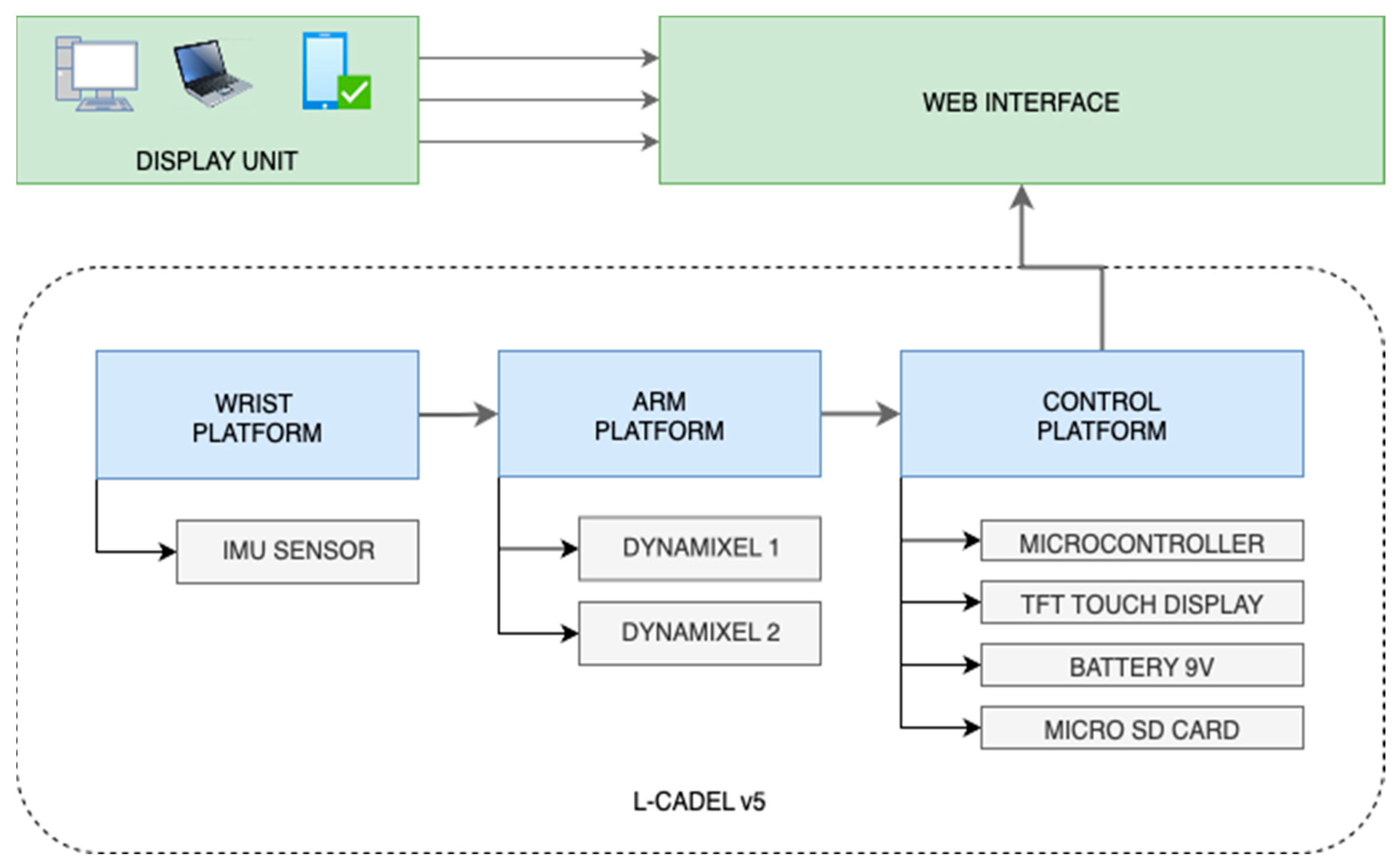
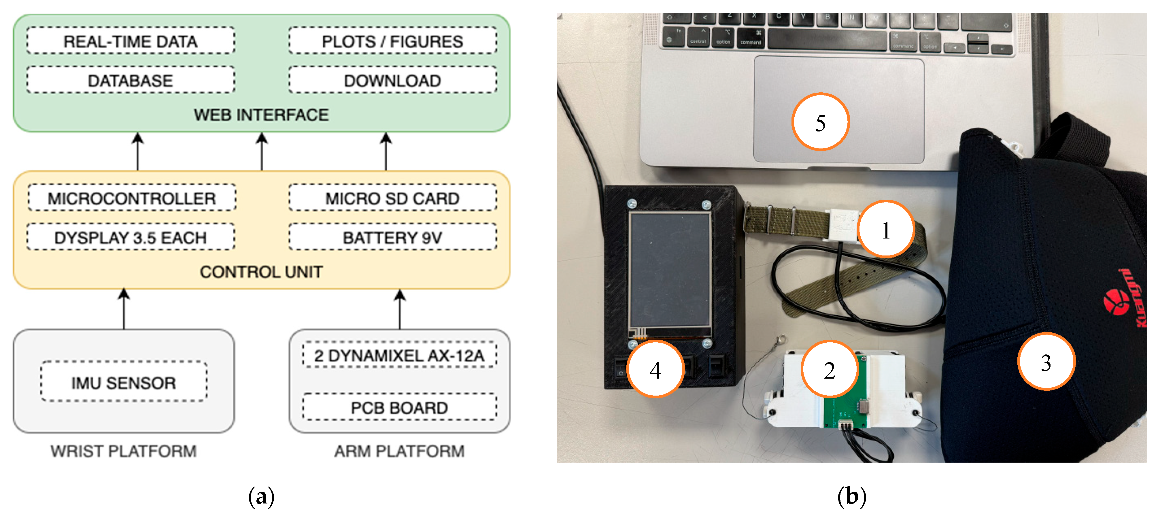
Based on previous versions of L-CADEL, the main difficulty for users was the arm platform, which is attached to the user’s arm. It was large in size and heavy, because it included a large number of elements. Therefore, the platform is quite difficult to attach to the user’s arm without additional assistance. In addition, it can move while the user performs the exercise. The design of the new version, L-CADEL v5, is conceived of three platforms with compact and lightweight solutions. It will allow the user to independently attach the platforms to the arm and wrist without additional help. The conceptual design shown in Figure 2 represents the general layout of the new design for L-CADEL v5. The new version of L-CADEL v5 consists of three platforms:
  • Wrist platform. It is a small size: about 25 × 25 × 10 mm with IMU sensor inside. The Type-C cable transfers the data from IMU sensor to a microcontroller.
  • Arm platform. It has a compact size of 85 × 50 × 35 mm and includes only the necessary elements: two servomotors of continuous rotation and a PCB board with a Type-C connection for data transfer.
  • Control unit. It is located outside and includes components for controlling the device and for data acquisition and data elaboration.
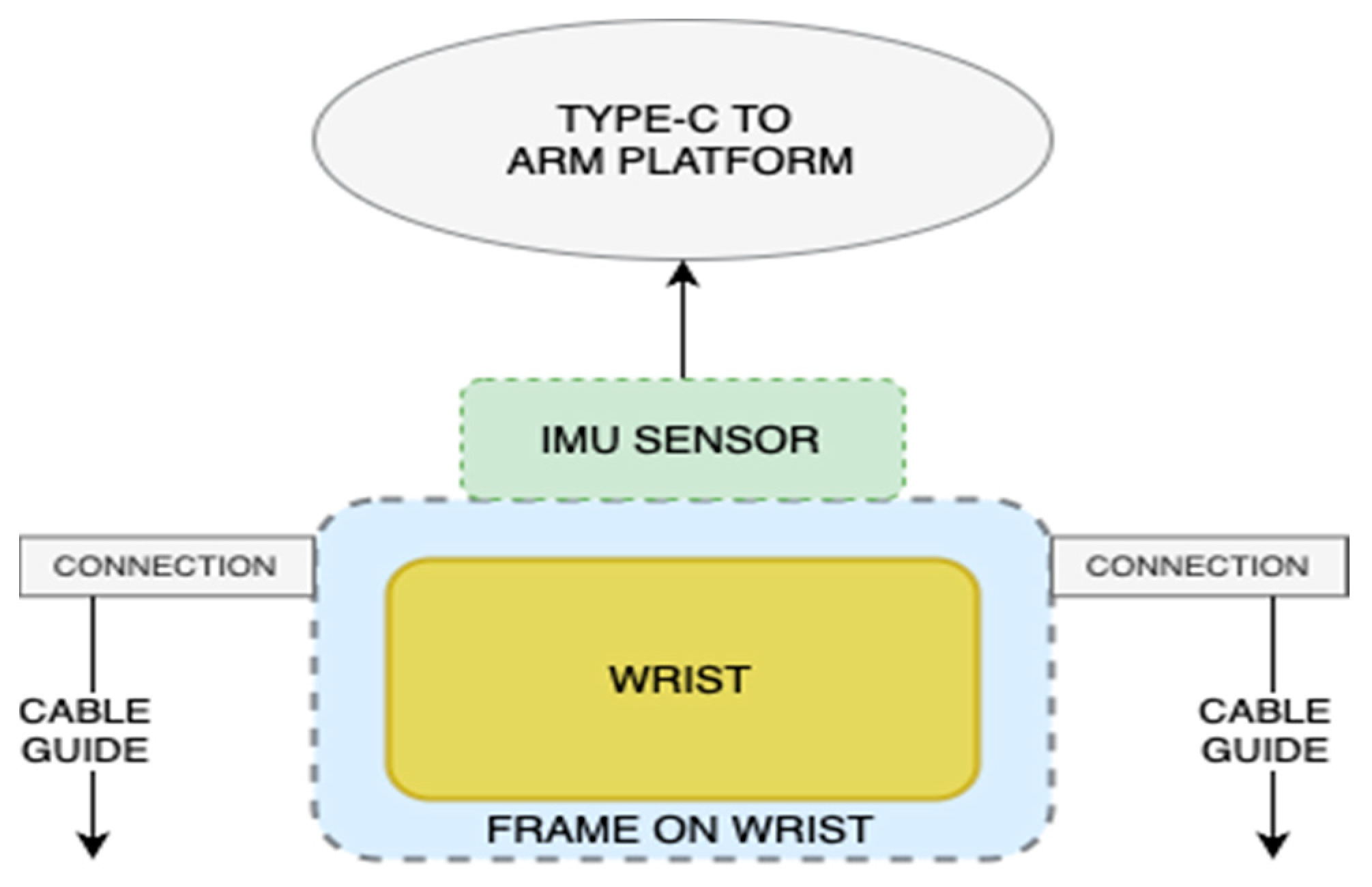
Figure 3 shows the conceptual design of the wrist platform with a Type-C cable to transfer the data to a microcontroller. Inside of the platform is an IMU sensor (BMI 160 or MPU6050, Bosch Sensortec, Gerlingen-Schlehöh, Germany) for measuring acceleration, orientation and angular rates. Because of that, the platform has a compact size of 25 × 25 × 10 mm and a weight less than 10 g. Four pins are used for the connection: the 3.3v pin of the IMU sensor is connected to the 3.3v pin of the microcontroller and provides power. GND is to the ground. SCL and SDA are responsible for data transfer to the microcontroller.
The mechanical design consists of two parts, as shown in the 3D model in Figure 4a. The first part is the main one. The IMU sensor is located in the middle and there are holes for the nylon strap on the sides. The second part is a cover, upon which the orientation of the sensor is indicated. It also allows for tight fixation of the cable and protects the sensor contacts from mechanical damage, as in Figure 4b. The platform is attached to the user’s wrist using a comfortable nylon strap. The strap allows the platform to adapt to any user, with the ability to also be used on the user’s clothing.
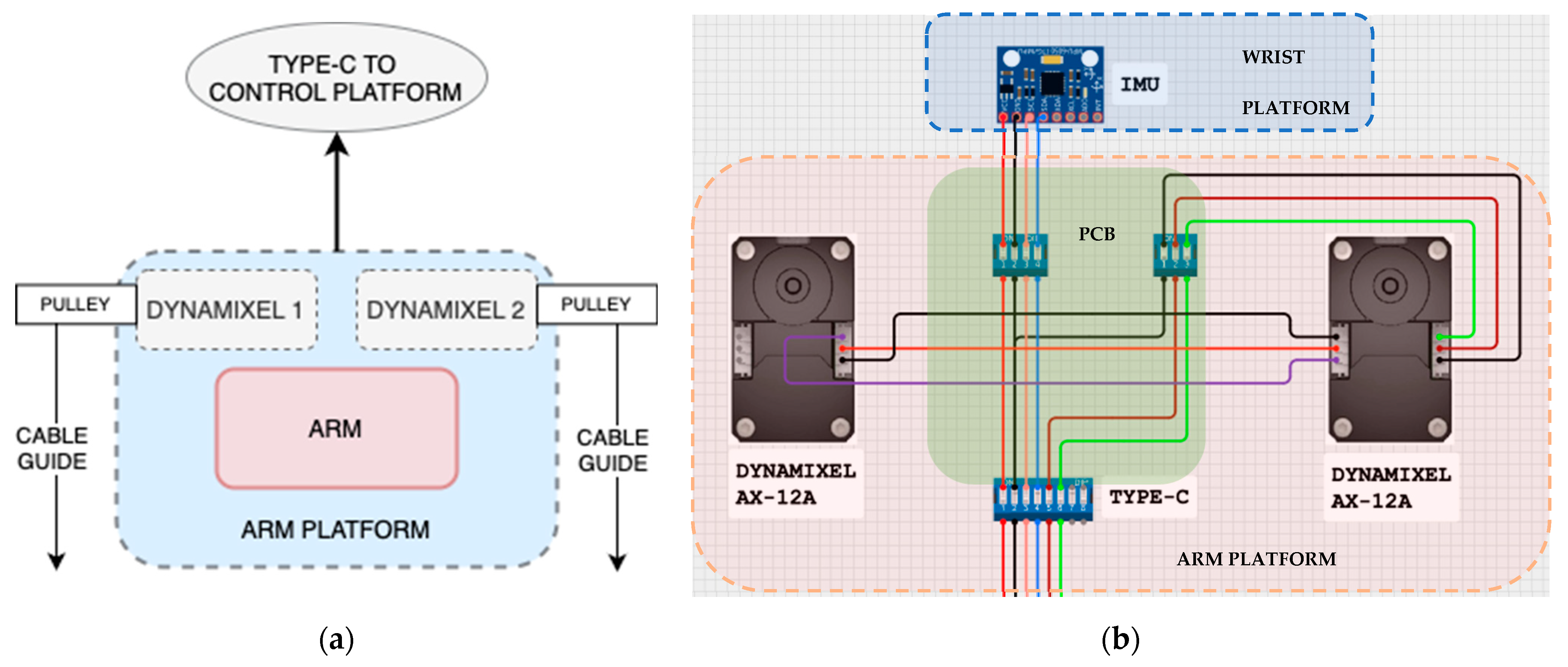
The arm platform is designed with a more lightweight solution, with respect to the previous design in L-CADEL v4. The conceptual design of the new arm platform, shown in Figure 5a, includes only the basic elements: two servomotors that provide flexion/extension movement of the forearm in the sagittal plane. DYNAMIXEL AX-12A (ROBOTIS, Seoul, Republic of Korea) continuous rotation servomotors, ref. [34], are used for this. They are located on the sides of the platform and secured with screws. This location and fastening ensure proper operation of the servomotors, as well as safety and comfort for the user. The circuit design is shown in Figure 5b. Both servomotors will transmit data via the Type-C connector to the microcontroller.
This version of the device uses DYNAMIXEL AX-12A servomotors [34], which have proper technical parameters for actuating elbow flexion and extension-assisted movements. The maximum drive torque is 1.5 N m, with a supply voltage of 12 V, providing sufficient force to reproduce the physiological range of motion. The average current consumption is 200–250 mA. The operating voltage range of 9–12 V allows for the use of a standard 9 volt battery as a power supply, which can be an advantage in terms of autonomy and portability of the device. Each DYNAMIXEL servomotor is equipped with built-in sensors, allowing the monitoring of data on the operation of each servomotor as load and input voltage. Its compact dimensions of 32 × 50 × 40 mm and light weight of approximately 54 g allow for convenient placement in the arm platform without significantly affecting the user’s movement and comfort device usage.
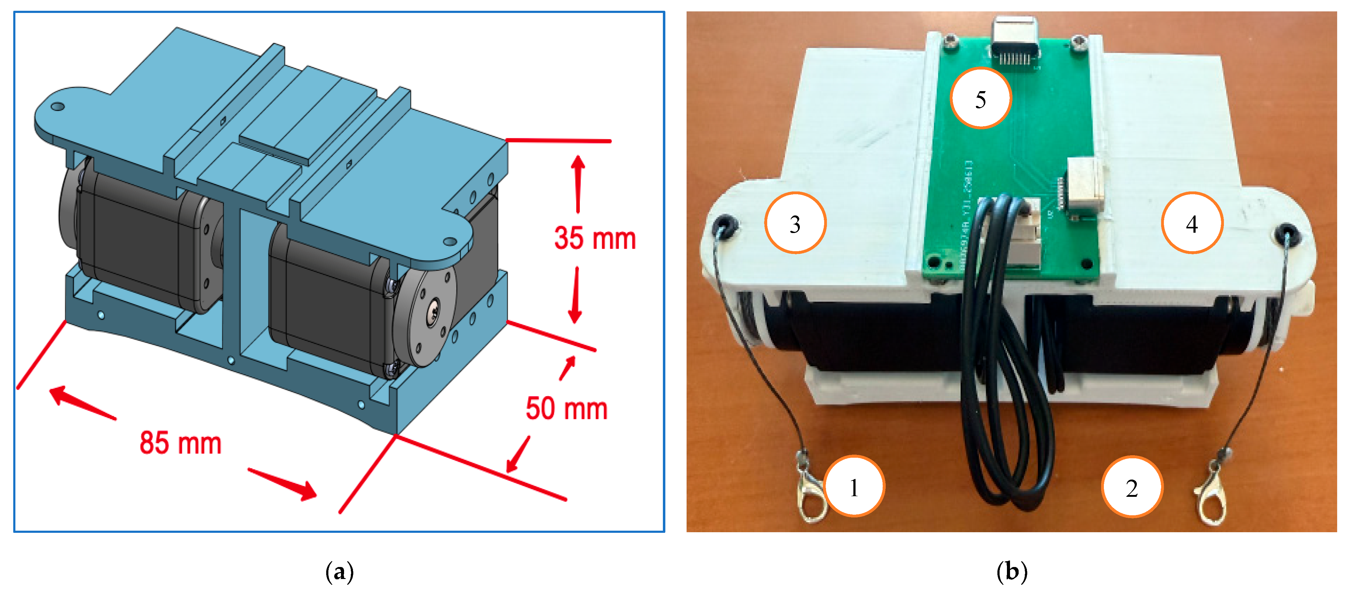
The new arm platform has been designed with a plastic arched frame, shown in Figure 6a. This frame is lighter and smaller than the previous L-CADEL versions with dimensions 80 × 45 × 30 mm and weight 150 gr. Two Dynamixel AX-12A servos are mounted side-by-side in a mirrored configuration. The upper part of the plastic house is a platform for installing a PCB board measuring 30 × 30 mm. The PCB board in Figure 6b as (5) is designed to minimize connecting cables. It is placed in the center of the plastic arched frame and is responsible for connecting all the elements of the arm platform. One triple terminal is designed to connect the Dynamixel AX-12A servomotors located on the sides of the plastic house. The Type-C terminal located on the top is designed to connect the wrist platform with an IMU sensor. The Type-C terminal located on the right is designed to connect to the control unit. The main elements of the platform are marked with numbers, Figure 6b:
  • (1) and (2) represent nylon cables with hooks at the end that connect to the wrist platform for performing the flexion–extension movement of the arm.
  • (3) and (4) represent the cover of plastic pulleys printed on a 3D printer for the Dynamixel AX-12A servo. Each cable is attached to a pulley and during rotation, the cable is wound on the attachment, performing the flexion–extension movement of the arm.
  • (5) represents a PCB board for connecting the Dynamixel AX-12A servo and the wrist platform (IMU sensor). This PCB board has a Type-C connector for connecting to the control unit.
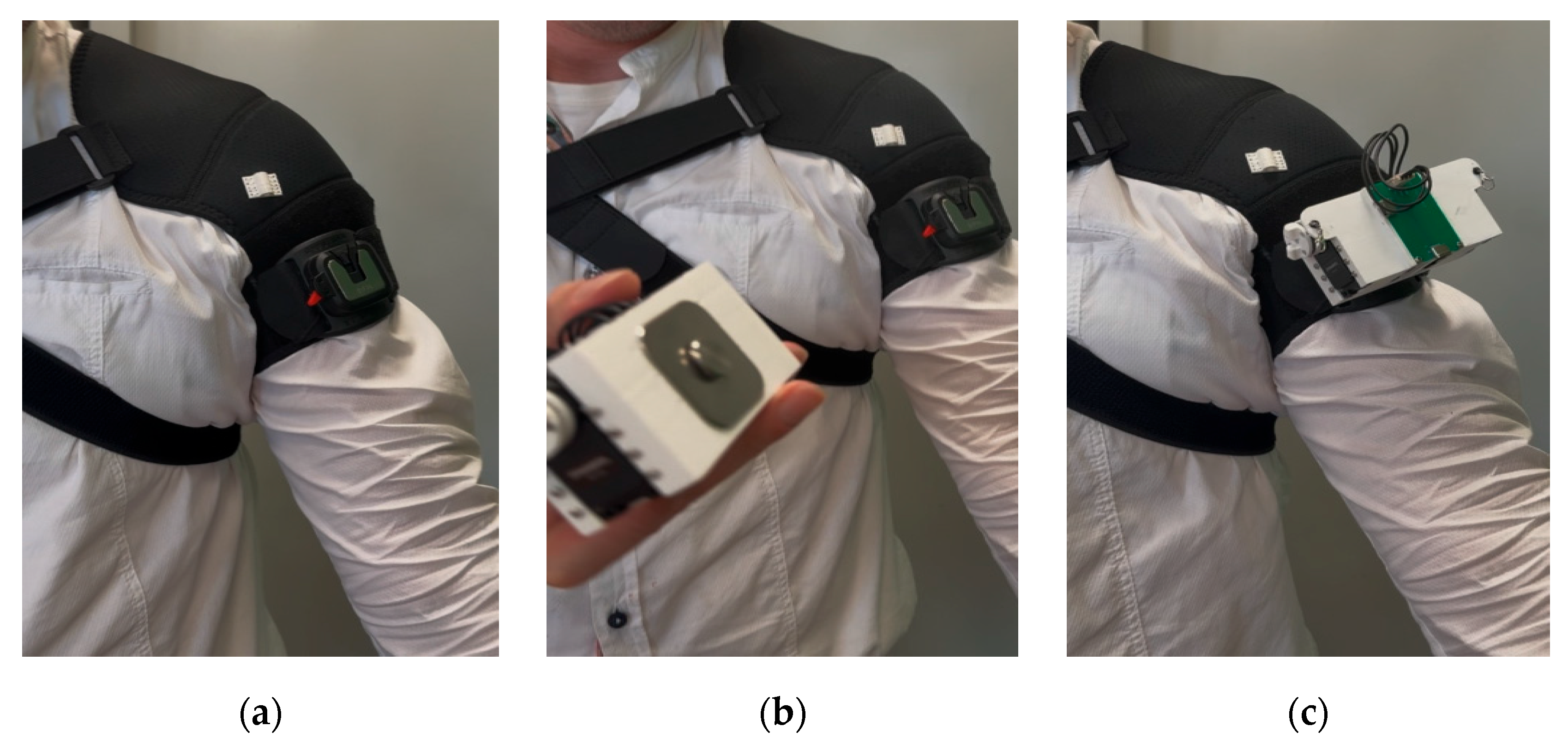
Figure 7 shows the elements of the shoulder support for attaching the arm platform to the user’s arm. To attach the platform, the user first needs to put on the shoulder support strap shown in Figure 7a. Then, the plastic element shown in Figure 7b is attached to the shoulder strap on the user’s arm through the holes on the sides. It is the base for attaching the arm platform. The steel buckle shown in Figure 7c is attached to the central part of the plastic element. For better fixation, the plastic element is equipped with a lock controlled by a red toggle switch. This solution is designed for firmly fixing the arm platform on the user’s arm.
Figure 8 shows the sequence of attaching the arm platform when the shoulder support strap is already put on the user. The plastic base put on the tape is fixed on the user’s arm, as shown in Figure 8a. The position of the plastic base should be in the middle of the biceps. This can be easily adapted to the user after fixing the tape. Figure 8b shows the attachment of the arm platform to the user’s arm with the stainless steel buckle. Figure 8c shows the final attachment of the arm platform on the user’s arm.
The control unit of L-CADEL v.5 is shown in Figure 9, with the main control elements of the device, communication with the web interface and a Micro SD card for storing data for post-processing. Figure 9b shows a 3D CAD model of the control unit box with dimensions of 120 × 80 × 35 mm. The cover is also used for placing a touch screen display and on/off buttons. A display allows users to control the device, select exercises for motion exercise and display data in real time. Experimental data are saved to the SD card and to the external database of the web interface for post-processing. The main element located in the control unit box is PCB board, shown in Figure 9c with compact dimensions of about 100 × 60 mm. It contains a microcontroller for controlling the device and a step-down regulator for converting voltage from 9 V to 5 V. This voltage is necessary to power the microcontroller, touch screen display and Micro SD Card. On the PCB board is located a 74LS241 buffer and a bidirectional level converter TXB0104 (Texas Instruments, Dallas, TX, USA), which is necessary for connecting servomotors to the microcontroller. The KF128 2.54 mm connectors located on the PCB board are used to connect a Micro SD Card to save data, a touch screen display to control the device and display data in real time, an EMG sensor to measure the user’s muscle activity and a power supply. One 9 V battery is used as a power supply for 1 h of work.
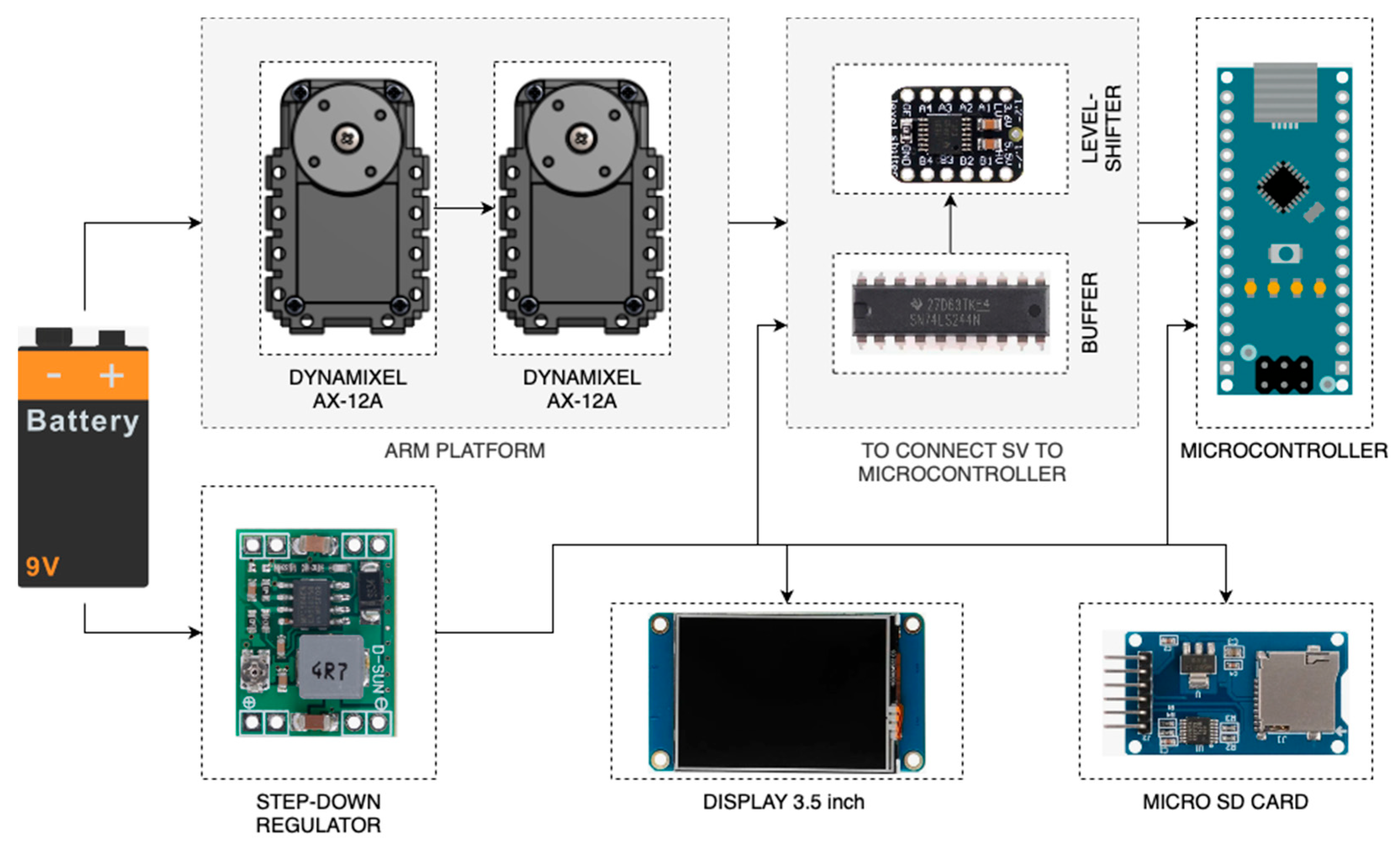
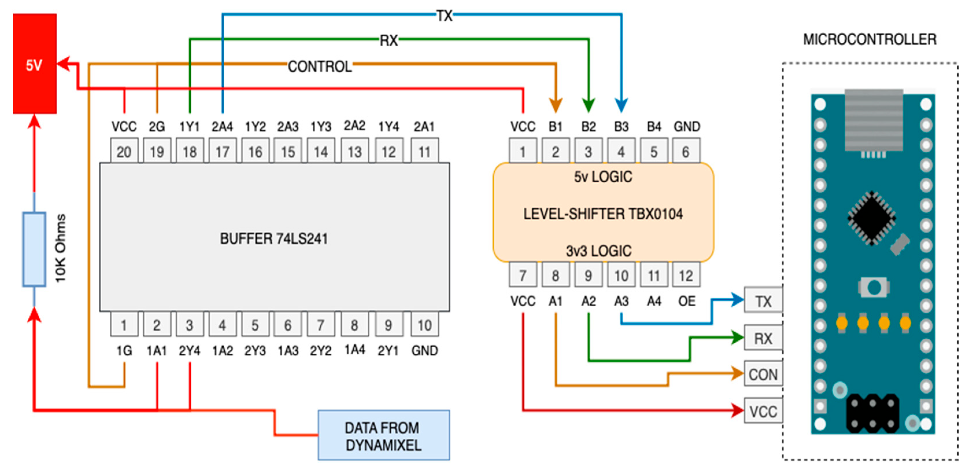
Figure 10 shows the connection circuit design. An input voltage of 9 V is provided for Dynamixel AX-12A servomotors. To power the microcontroller, touch screen display and Micro SD Card, 5 V is required. To power the wrist platform and level-shifter, 3 V is required. Using a step-down regulator from 9 V to 5 V, it is possible to use only one 9 V battery to power the entire system for 1 h of work. The step-down regulator provides voltage conversion from 9 V to 5 V to power the microcontroller, touch screen display, buffer, level shifter and Micro SD Card. To provide 3 V of power for the wrist platform and level-shifter, the 3v3 microcontroller pin is used. A 74LS241 buffer and a bidirectional level shifter, TXB0104, with compact dimensions of 10 × 20 mm each and weight less than 20 g are used to control Dynamixel AX-12A servomotors through a microcontroller. To control the Dynamixel AX-12A servo drive with a microcontroller (with 3.3 V or 5 V logic), it is necessary to provide bidirectional half-duplex single-wire communication (Dynamixel TTL protocol). However, the microcontroller uses separate TX and RX lines. Also, the microcontroller and the AX-12A servomotors have different logic: 3.3 V and 5 V, respectively. To coordinate levels and organize the half-duplex, two elements are used: the 74LS241 buffer and the TXB0104 level shifter. The circuit is shown in Figure 11. The 74LS241 buffer is designed to implement half-duplex single-wire communication between the microcontroller and the Dynamixel AX-12A servomotors. TX and RX from the microcontroller are connected to one input of the 74LS241 buffer and the buffer output is connected to the microcontroller via the bidirectional level shifter, TXB0104. To avoid conflicts of transmitting and receiving signal, a directional signal, OE (output enable), is used. It has two positions: the buffer is enabled (OE = LOW) when the microcontroller transmits data and disabled (OE = HIGH) when the servomotor responds. The buffer also provides current protection and prevents damage.
TXB0104 is a 4-bit bidirectional level shifter with automatic direction detection. It is used to convert logical levels between the microcontroller and the Dynamixel AX-12A servomotor. This version of the device used a microcontroller with 3.3 V logic and the Dynamixel AX-12A has 5 V logic. TXB0104 automatically detects the signal direction and provides safe conversion between 3.3 V and 5 V logic. It also protects the microcontroller from the high level of 5 V that comes from the Dynamixel.
The designed communication is as follows: the microcontroller generates a UART signal with 3.3 V logic; the signal passes through the bidirectional level shifter TXB0104 and is converted to 5 V. The already-amplified 5 V signal is fed to the input of the 74LS241 buffer. If the OE (output enable) of the 74LS241 buffer is active (LOW), the buffer transmits the signal to the Dynamixel DATA line and the Dynamixel servo receives and executes the command.
L-CADEL v5 uses a 3.5 inch touch screen display with designed windows, as shown in Figure 12. When the device is turned on, the system automatically checks all elements and sensors and displays the result on the display shown in Figure 12a. Thus, the user is informed that all elements of the system are connected correctly. If any element or sensor of the system is not connected well, an error will be displayed opposite this element. Next, the display provides the setup shown in Figure 12b. It allows users to rotate the servomotors in one direction and the other to ensure the correct cable tension before starting the exercise. It is also possible to select a Wi-Fi network, as shown in Figure 12e. The system automatically scans the available Wi-Fi networks and displays a list. The user only needs to select the Wi-Fi network and enter a login and password. Using Wi-Fi, it is possible to establish a connection with the web interface to control the device and receive data in real time. The data transfer is performed on the basis of Websocket with SSL, to protect the data.
Figure 12c shows a list of motion exercise programs. At the moment, three exercises are presented differently in terms of the speed of exercise. Each exercise includes three repetitions of flexion–extension movement. The first exercise’s servomotor has a speed of 20% for the repetition of flexion–extension at about 50 s. The second exercise’s servomotor has a speed of 50%, which allows the user to perform a repetition in 25 s. The third exercise’s servomotor has a speed of 100%, which allows the user to perform a repetition in 6 s. During the exercise, a user can see real-time data on the display. The main figure is the pitch and roll angles, shown in windows like in Figure 12d. A user can also view other data in real time, such as acceleration components from the IMU sensor, power consumption from Dynamixel servomotors and muscle activity from the EMG sensor.

2.3. Web Interface

A web interface shown in Figure 13 is designed for data acquisition and data elaboration. It allows a user to control the L-CADEL v5 assisting device and allows a physiotherapist to see the results of the exercise in a convenient format. A user can use the web interface from any device (laptop, tablet or smartphone) at any time and from anywhere in the world. The web interface also supports any operating system, such as Windows, Mac OS, Android or Linux. All exercise data, videos, messages and notifications will be securely stored in the cloud. The identification system will protect the personal data of users, and the firewall, antivirus system and data encryption will protect against unauthorized access. The web interface is also convenient in terms of implementing updates and expansion. In the case of updating the system, adding new functionality and connecting new assisting devices for motion exercises will not require any action from users. The system will automatically provide users with new opportunities.
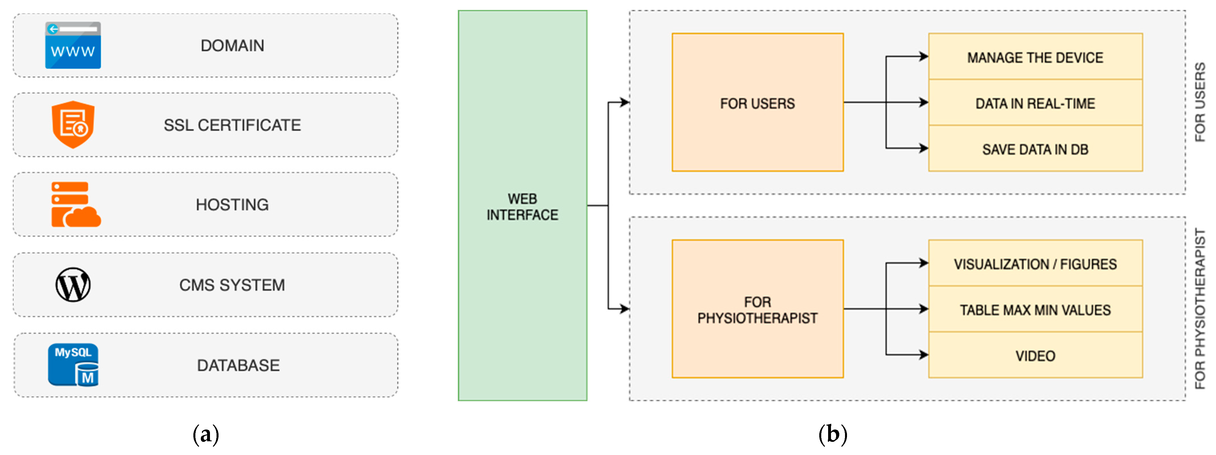
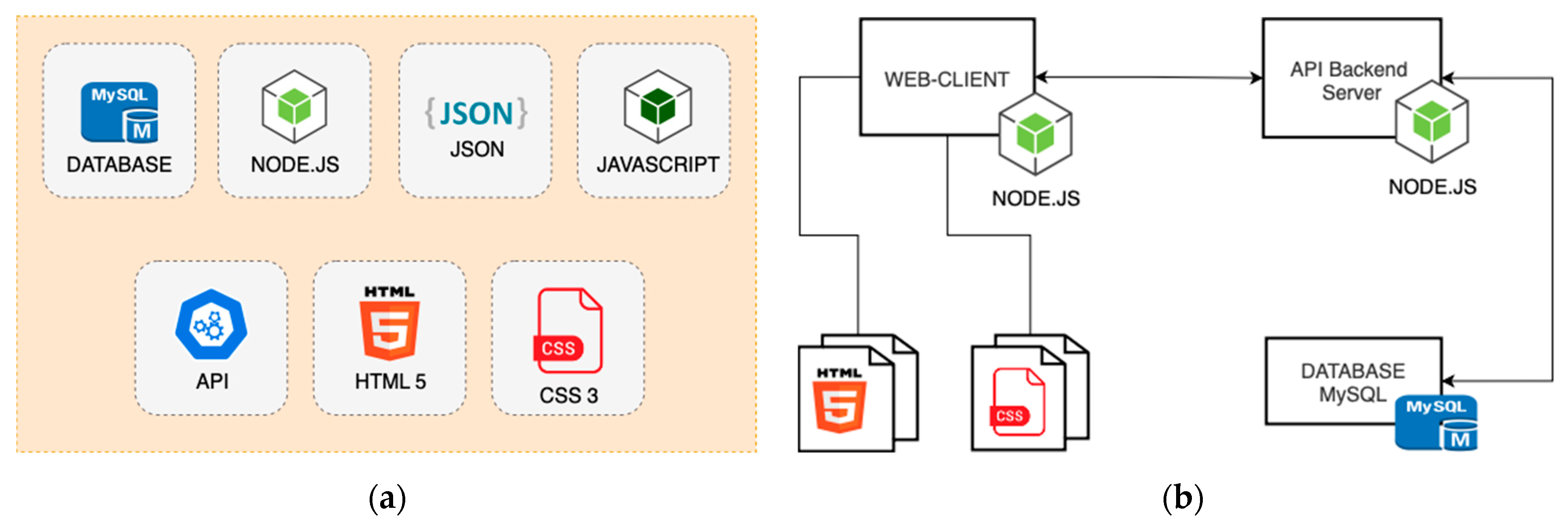
Figure 13a shows the main elements of the designed web interface. Firstly, the domain and hosting are selected. The name in the .com zone is chosen as the main domain. An SSL (secure sockets layer) certificate is installed on the domain, which is necessary for authenticating the identity of the website and establishing an encrypted connection between the web server and the user’s browser. VPS is chosen as a host, which is characterized by increased performance and better security. Full root access allows the user to change the server configuration and update the software, providing more flexibility and mobility. A CMS system is used as a management system. It is used to manage content and moderate the added data from experiments. The data of user’s exercises are stored in a MySQL Database located on the server and used to display figures for physiotherapists. Figure 13b shows the web interface diagram, which consists of two parts. The first part of the web interface is intended for users. Using the client–server model, it connects to the assisting device via Wi-Fi. This part represents the control interface for the assisting device. Using a PC, laptop or smartphone with any operating system, a user can control the assisting device and can select the necessary exercises to perform. The data will be displayed in a graphical format in the user’s web interface in real time. The data of the exercises will be automatically saved in the database and the physiotherapist will receive a notification about this. The second part of the interface is intended for physiotherapists. It allows them to see the results of exercises performed by users. Each physiotherapist will have a list of the users and all the data on each exercise. Visualization in a graphical format will allow physiotherapists to see the results in more detail, conveniently and quickly. The video of the exercise, integrated with figures, will allow us to understand the nuances of the user’s exercise performance in more detail. A table with min and max values and an average will provide additional information so that physiotherapists can understand the results in detail.
Figure 14a shows the elements of the web interface for users. The main element is WebSocket, which is necessary for real-time communication. API and Node.js are used for connection and data transfer. JSON format is used for transferring structured data. HTML 5 and CSS 3 are used to create an interface adapted to any device. JavaScript allows us to visualize data in a graphical format. MySQL Database is used to save the data of the experiments performed.
The main task to make it work is to choose the right client–server model. This will facilitate fast and cost-effective data exchange with low latency, as shown in Figure 14b. A solution for real-time communication between a client and a server with low latency is a Websocket, as shown in Figure 14b. The client will enter the IP address of the server on the browser, sending a “WebSocket Handshake”, which is a request for an http refresh from the server. The server will then respond with “HTTP 101”, indicating that the connection is open and a WebSocket has been established between the server and the client. There is now an open connection between the client and the server, and this connection is permanent, and bidirectional messages can be sent. Between the two, the Client will receive real-time data from the server without sending any requests. This connection is closed when one of the parties closes the channel.
The second part of the web interface is designed for physiotherapists. Figure 15a shows the elements of this part of the web interface. The main elements are MySQL database that stores the data of experiments and JavaScript libraries used to visualize the figures in a user-friendly format. It allows us to select a line and time interval for each figure, view it in full-screen and save data in various formats (JPEG, PNG, SVG, CSV or XLS) in one click. Various JavaScript libraries are used to visualize the figures: highstock.js, exporting.js, export-data.js, accessibility.js. They are used together with Html 5 and CSS, which are required to connect the library and describe the frame for plotting the figure. Figure 15b describes the scheme. Data are stored in the MySQL Database. Through the created API on Node.js, Web Client requests data and receives it in JSON format. The JavaScript library receives the requested data, configures the axes and labels and plots the figure. Then, JavaScript dynamically updates and filters the data. According to Figure 15b, the client (Frontend) sends a request to the API to receive data from the server (Backend); then, the server (Backend) sends the requested data to the client (Frontend) in JSON format. Dynamic chart updates are essential for data visualization, to ensure that figures and charts remain accurate, responsive and interactive as new data comes in. This allows us to keep the data up to date without manual refreshing, optimizes performance by refreshing only the necessary parts and allows us to synchronize multiple charts. This part of the web interface will allow the physiotherapist to obtain the result of the user’s exercise in a convenient graphical format. The main figures can be in terms of pitch, roll and yaw angles; acceleration components and angular velocities from the IMU sensor; power consumption from servomotors and user muscle activity measured by the EMG sensor. The physiotherapist can select a line and time interval for each figure, and they can save the results in various formats (JPEG, PNG, SVG, CSV or XLS). A table with minimum and maximum values, a video recording of an exercise and the average will provide additional numerical information.
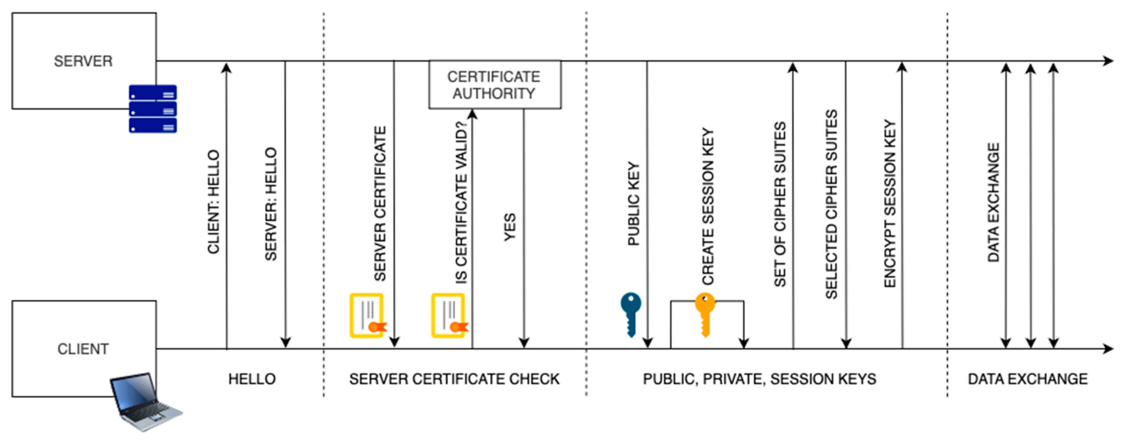
The cyber security includes several elements to protect the system and the data. One of the main elements is encryption using cryptographic algorithms, hash functions and protocols. This is used in the SSL and database for secure transmission and storage of data. This will ensure the protection of information and its integrity. It allows operation over HTTPS (Hypertext Transfer Protocol Secure) using key encryption, authentication and integrity components. HTTPS is based on data encryption. This ensures the confidentiality of data during transmission. This cryptographic layer protects information, even if it is intercepted. Guaranteeing data integrity is another foundation of HTTPS. It guarantees that the information arriving at its destination has not been subject to unauthorized changes. Cryptographic hash functions are responsible for this. Authentication is another foundation of HTTPS. HTTPS provides reliable authentication mechanisms. This is achieved through the use of digital certificates, which are cryptographic credentials issued by trusted certification authorities (CA) that confirm the identity of the server. That is why in the interface for users and for physiotherapists, SSL certificate is used.
HTTPS works as shown in Figure 16. The interaction between the client (user’s browser) and the server begins with a handshake. The client initiates a handshake by sending a “Client Hello” message to the server. This message indicates the client’s intent to establish a secure connection. In response to the client’s hello, the server sends a “Server Hello” message. The server also sends its digital certificate to the client. The client, having received the Server certificate, proceeds to verify the authenticity of the certificate and includes confirmation that it was issued by a trusted certificate authority. This verification is critical to establishing trust in the identity of the server. After passing the verification, the client extracts the server’s public key from the certificate. This public key is an integral component for the subsequent encryption and decryption processes. A session key is then created, which will be used by the client and server and will be the basis for encrypting and decrypting data during the session. During the key exchange, the client and server agree on a common cipher suite. This suite covers the cryptographic algorithms and protocols that will be used for encryption during the session. The agreement ensures compatibility and security. After the key exchange, the client and server can begin exchanging data. When exchanging information between a client and a server, the data are transmitted in encrypted form. The sending side encrypts the data, and the receiving side decrypts the data. AES-256 is used as the encryption algorithm. This is a symmetric encryption algorithm, the advanced encryption standard (AES), with a 256-bit key, which provides strong data encryption and ensures resistance to hacking attempts by modern computer systems. This encryption algorithm is used in the MySQL database for secure data storage and is also used for secure data transmission between the browser and the server.
For hosting, VPS hosting (virtual private server) was selected. This type of hosting provides full access and control over the server and installation of additional software and scripts. This type of hosting includes more CPU cores and more RAM, which directly affect the speed of the web interface and data processing. Improved server security allows for daily automatic scanning for malware. Protection against DDoS attacks and an advanced firewall provide additional system protection. Constant automatic server monitoring allows us to fully control it and receive alerts in the event of non-standard situations.
Cryptographic algorithms, hash functions, protocols and firewalls reliably protect the web interface from unauthorized access and data interception. All data between the client and the server are transmitted in encrypted form over a secure communication channel. Automatic backup to the cloud allows us to have a copy of the system and be able to restore it quickly, in case of unforeseen situations.

2.4. Testing Layout

Laboratory experiments were supervised by one of the authors. The aim of the experiments was to check the functionality of all parts of the prototype and its integration with the web interface. A separate task was to test the prototype in terms of user friendliness. The testing was conducted based on a designed experimental protocol.
The conceptual design of a testing layout is shown in Figure 17a, consisting of two platforms placed on the wrist and arm, the control unit and the web interface. The wrist platform, as (1), includes an IMU sensor for measuring the user’s forearm movement. The data are transmitted to the control unit. The arm platform, as (2), includes two servomotors, DYNAMIXEL AX-12A, for performing the flexion–extension movement of the elbow joint. The arm platform house with two servomotors is attached using the shoulder support, as (3), to conveniently and securely wear on a user’s arm. Control unit (4) includes elements for controlling the device, data acquisition and data elaboration. The Wi-Fi module allows connection to the web interface, using a WebSocket with SSL protocol. The data of assisted motion exercises are saved to the Micro SD Card and to the web interface for post-processing. Figure 17b shows the experimental setup that is arranged with a laptop for comfortable use of the web interface and the display of data in real time.

2.5. Cost Analysis

Table 2 shows the cost analysis of the components for the design of the L-CADEL v.5 prototype. The total cost of the prototype is less than 200 EUR, making it affordable to potential elderly users. The most expensive component is the DYNAMIXEL AX-12A servomotor [34]. The remaining components do not exceed 50 EUR in total.

3. Results

A L-CADEL.v5 prototype has been validated in the LARM2 laboratory of the University of Rome Tor Vergata. Several tests have been carried out on seven volunteers, with the aim to validate the design’s feasibility with proper features and to characterize the operation performance in proper motion assistance. All seven volunteers had satisfactory elbow mobility without any history of traumatic injuries. The age group of participants was 30–40 years. During testing, volunteers appreciated the ease of use of the device, thanks to its intuitive controls and the naturalness of the movements. Furthermore, according to the designed protocol, in addition to the consensus and data, participants reported comfort during cyclic exercises, indicating proper kinematic synchronization and the absence of arm discomfort. The sequence of five snapshots in Figure 18 illustrates an elbow flexion–extension exercise performed by a volunteer using the L-CADEL v5 device.
According to the designed experimental protocol in [32], the initial volunteer posture is arranged by sitting in front of the table, and the hand is on the table, as shown in Figure 19a. The user performs three repetitions of elbow flexion/extension movement three times with a natural speed of about 30 s/cycle. The device operates with no specific closed-loop control, in addition to an open-loop servomotor regulation. An IMU sensor [36] is attached to the user’s wrist to measure the forearm angle. During exercise, the device continuously reads this angle. There are two angle limits: one corresponds to the maximum flexion (90°) and the other to the maximum extension (0°). When the angle measured by the IMU reaches the upper limit (90°), it is interpreted as the end of the flexion phase, and the direction of rotation of the servomotors automatically reverses, beginning the extension phase. Similarly, when the angle decreases to the lower limit (0°), the system reverses the direction of rotation again, transitioning to flexion. This operating principle allows the device to continuously cycle between these two limit positions that can nevertheless be properly prescribed before the exercise, according to the user’s conditions and needs. The user-oriented features of this operation method make the device suitable for repeated movements between fixed limits without the need to adjust intermediate states and with minimal computation.
In Figure 18a, at the initial position, the user’s left arm is fully extended and the forearm rests on the table with the palm facing up. The arm platform is securely fastened with a shoulder support strap. The IMU sensor located in the wrist platform marks the starting point of the movement as 0 degrees. In Figure 18b, the user starts to bend the elbow, raising the forearm at an angle of approximately 45 degrees; the wrist is slightly turned out and the fingers are relaxed. In Figure 18c, the arm reaches full flexion, the forearm is almost vertical and the palm is facing the user’s face. At this point, the value of the IMU sensor located on the user’s wrist reaches 90 degrees. This is the starting point for the command to change the direction of rotation for the servomotors: that is, the calculation of the trajectory of movement based on the data of the IMU sensor located on the user’s wrist. As soon as the desired point is reached, a command is given to change the direction of rotation of the servomotors: 0 degrees for full extension and 90 degrees for full flexion. Figure 18d captures the lowering phase, when the forearm is again half-extended, which mirrors the position in Figure 19b, but in reverse movements. Finally, in Figure 18e, the arm returns to the initial fully extended position, completing the movement cycle. In all images, the user remains in a sitting position. The wrist platform and the arm platform of the device are fixed on the user’s wrist and arm, respectively, which confirms their stability and functionality during exercise. The L-CADEL v5 device is sufficiently flexible to accommodate individual user differences. If the START/STOP positions of the flexion–extension movement do not correspond to those shown in Figure 18, this does not significantly affect the planned range of motion and the accuracy of data recording. The design and data-processing algorithms allow the range of angular movements to be adapted to the anatomical and functional characteristics of a specific user before the exercises.
The design of the device and software allow for a change in the operating mode, providing both passive and active movement. In passive mode, elbow joint movements are completely controlled by the drive, without the user’s muscle involvement, reducing stress on the joint. In active mode, the device partially supports the user’s movements by stimulating muscle activity and improving coordination, allowing for a gradual increase in the functional activity of the limb during training. A load mode is also available, in which the limb is subjected to an additional external load (e.g., 5 N), and the device adapts the servomotors to maintain a predetermined range of motion.
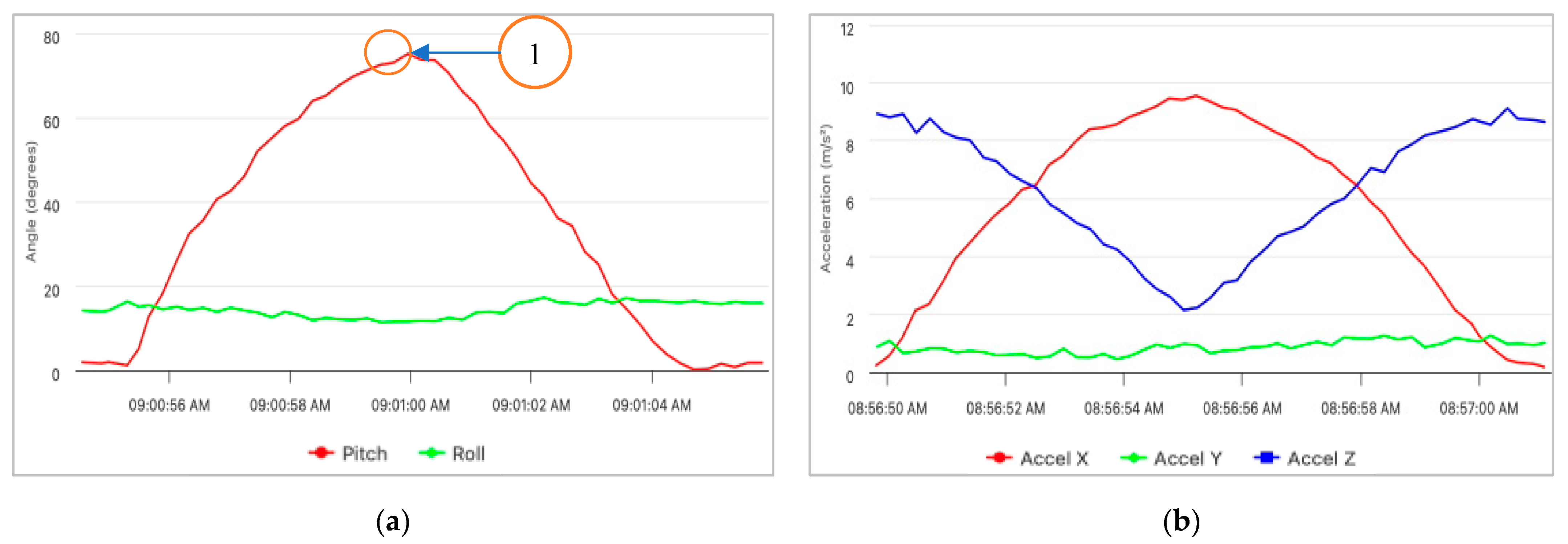
Figure 19 shows the result of real-time data visualization in the web interface. Using the Wi-Fi module and the client–server model, the microcontroller located in the control unit transmits data in JSON format to the WebSocket. Using the main elements of the web interface and the JavaScript libraries, the data are displayed in a graphical format with small latency. Figure 19a shows the acquired data for the angles. The pitch angle is shown in red and the roll angle is shown in green. The reference frame is as in Figure 4a and Figure 18a, with the pitch angle as the rotation around the Y-axis and the roll angle as the rotation around the X-axis. The figure shows one flexion–extension cycle. Full flexion is shown in the center under circled number 1 in Figure 19a. The pitch angle shows the normal movement of the user’s arm in the sagittal plane. The roll angle shows that the user’s arm moves from side to side during the exercise. The calculation of the angles is performed on the web interface side in real time. Figure 19b presents the acceleration components of the IMU sensor. Ax represents the acceleration in the sagittal plane in the horizontal direction. This component shows the strongest fluctuations, reflecting the flexion–extension movement of the elbow.
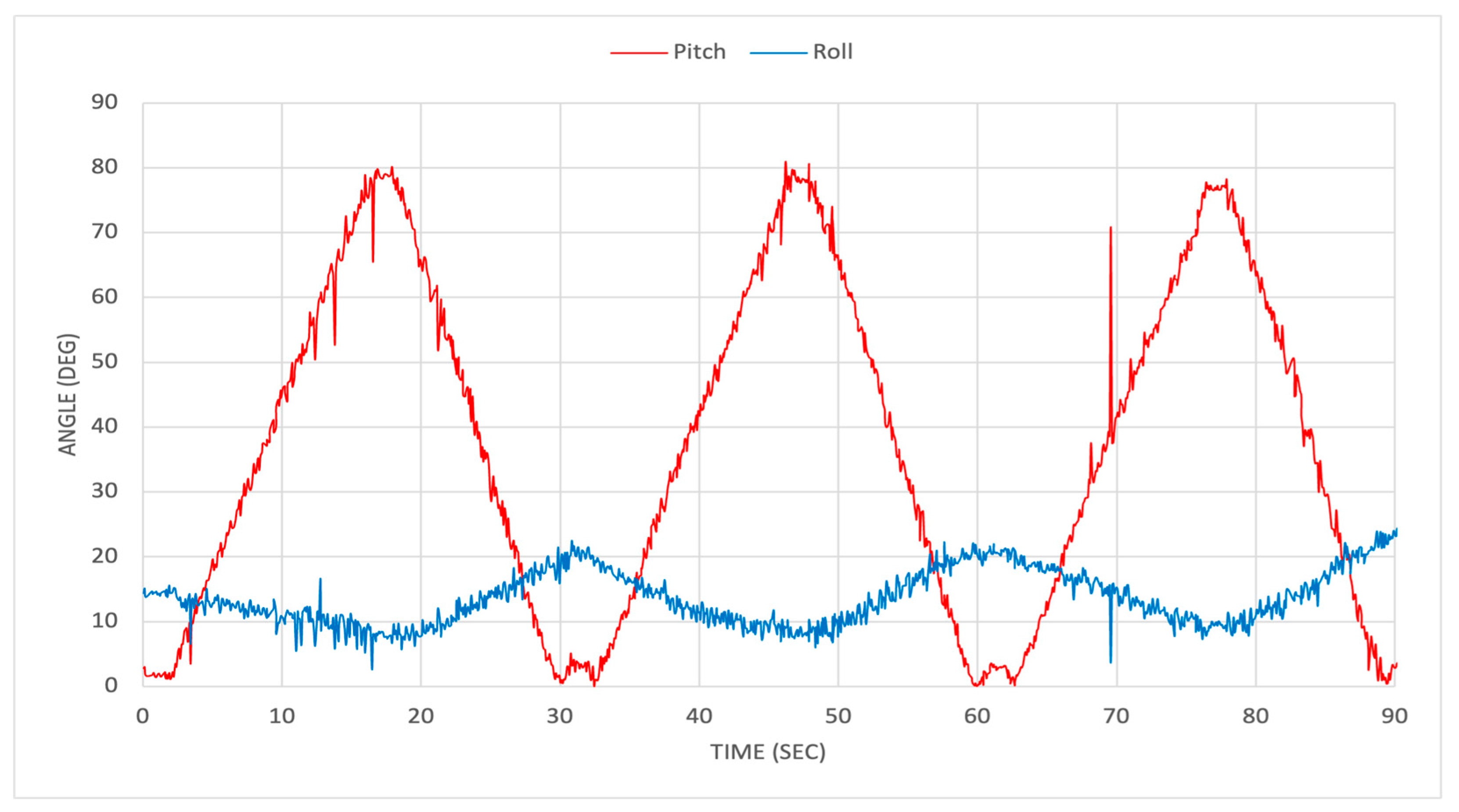
Figure 20 shows the pitch and roll angles while a user performs three repetitions of the elbow’s flexion–extension movement at a natural speed of about 30 s per cycle. They are calculated based on the acceleration components of the IMU sensor. The IMU sampling rate is set as 100 Hz without any filtering methods. The goal of this approach is to preserve the original data structure for evaluating the performance of detecting the response as coming from the human motion and tissues. However, the inclusion of adaptive filters in future versions of the device can reduce the noise due to sensor design and to provide more precise motion control in real time.
The pitch angle values range from 19.35 to 68.90 degrees, calculated by
P i t c h = a t a n 2 a x a x 2 + a z 2 ,
where ax, ay and az are the accelerometer components of the IMU sensor located on the user’s wrist.
As for the roll angle, the expected values should be almost constant, indicating that the movement occurs only in the sagittal plane. However, during the experiment, we obtain a roll angle value that ranges from 11.20 to 24.89 degrees. This indicates that the user’s forearm moves from side to side during the exercise. The roll angle is calculated by
R o l l = a t a n 2 a x a y 2 + a z 2 ,
where ax, ay and az are the accelerometer components of the IMU sensor located on the user’s wrist.
Due to human anatomy, the roll angle value is not constant and indicates the user’s forearm movement out of the sagittal plane. However, the values of the angles represent a smooth and efficient operation of the device during the three exercise cycles. Noise in the angle values may be caused by slight movement of the tested platforms, because some of them may be fixed on the user’s clothing. Anatomical features of the user, a slight tremor during the exercise or mechanical errors in cable connections may also be the cause of noise.
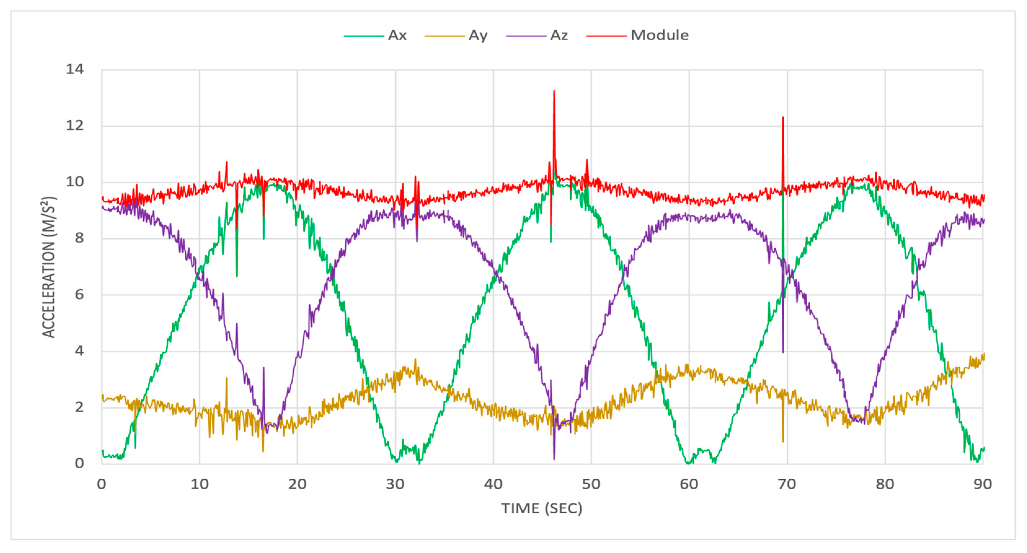
Figure 21 shows the acceleration components of the IMU sensor located on the user’s wrist. Small noises in the values may be caused by user fatigue or cable tension errors. The ax and az components represent the acceleration in the sagittal plane in horizontal and vertical directions, respectively. The ax and az components have values in the range from 0 g to 9.88 m/s2 and from 2.33 g to 8.98 m/s2, respectively. They correspond to the cyclic motion during forearm flexion/extension and indicate periodic changes in the horizontal and vertical positions. There is similar dynamics in all three repetitions because the servo-rotation speed is constant, and the rotation change is performed automatically as based on the pitch angle calculation. The value of the ay component is not constant in the range from 2.34 to 4.12 m/s2. This indicates that the user’s wrist movement does not only occur in the sagittal plane. The user’s wrist moves from side to side during the exercise. The module of the acceleration vector is calculated by
| a | = a x 2 + a y 2 + a z 2 ,
where ax, ay and az are the accelerometer components of the IMU sensor located on the user’s wrist.
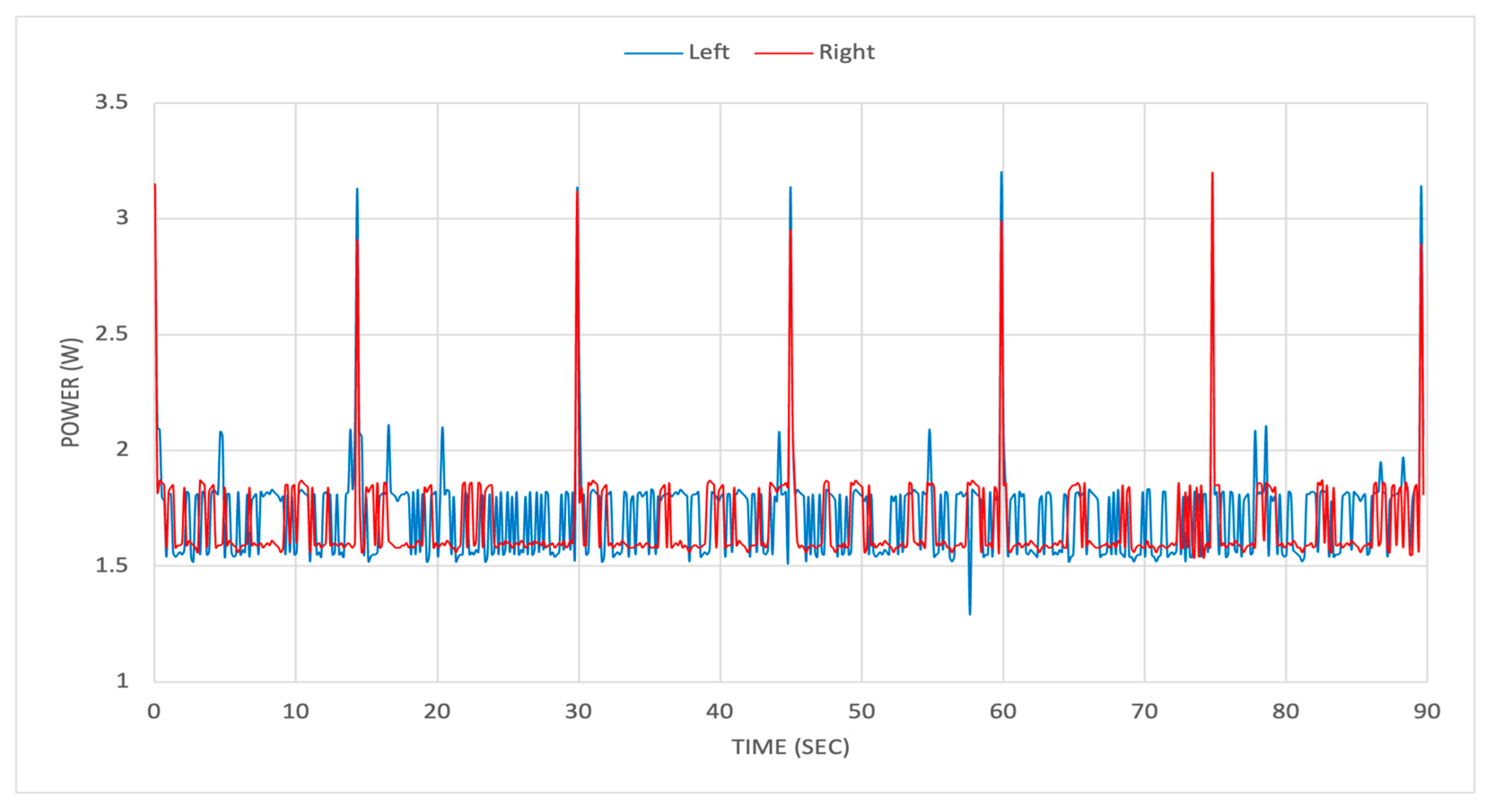
Figure 22 shows the power consumption data from the two Dynamixel AX-12A servomotors. The servomotors show the same dynamics during flexion and extension of the elbow joint in the range of 1.5–1.8 W. The spikes in the values indicate a change in the rotation of the Dynamixel servomotors. The plot shows the minimal differences between the two servomotors during three cycles of a flexion–extension exercise. This may be an indicator of satisfactory operation of two servomotors in parallel, with the power source of a 9 V battery.

4. Discussion

The L-CADEL.v5 device is an effective design for the motion exercise of the elbow joint. Thanks to two servomotors located on the arm platform, the flexion–extension movement of the elbow joint is performed in the sagittal plane. Changing the programming part allows us to control the change in the rotation of the servomotors automatically, based on the IMU sensor data. The IMU is located on the wrist platform to track acceleration, orientation and angular rates with a more compact solution, weighing about 20 g. Thanks to the nylon strap, it is convenient to attach the wrist platform to the user’s wrist without additional help. Also, it can be used even on the user’s clothes. The arm platform is designed to be lighter and more compact, because it only includes the necessary elements. Two Dynamixel AX-12A servomotors are located on the sides of the platform and are responsible for the flexion–extension movement of the elbow joint. The weight of the platform has become several times lower compared to previous versions and is about 160 g. The shoulder support and plastic base with a stainless steel buckle help to securely attach the platform on the user’s arm. This form of fixation on the platform allows us to adapt it to the anatomical features of the user and allows the user to avoid displacement of the platform during an exercise. The control unit includes the main elements for controlling the device and transmitting data in real time to the display and web interface. The Wi-Fi module allows the device to connect to the web interface and send data in real time to the WebSocket, using the SSL protocol to protect data. The developed web interface helps a user to control the device and to receive a graphical display of data in real time. A supervising physiotherapist receives the results of the user’s exercise in graphical form, with the ability to download figures in different formats. Exercise data are saved on a Micro SD Card in *.txt format, as well as in an external MySQL database web interface for post-processing. The lab testing was a short-term activity involving a limited number of device cycles, referring to exercise sessions like typical motion therapy. Long-term durability and reliability issues were not addressed, since the paper’s aim is to show the design features and tested proof-of-concept feasibility. Critical aspects for home-use devices, such as material wear, long-term servo-performance under repeated cyclic loads and overall design durability will require further activity. Future work will be planned to include comprehensive durability testing with proper operating cycles, as well as an analysis of the key component wear and of the long-time operation performance of the device within a significant clinical testing campaign, with a proper number of volunteers. Such an extended testing activity will assess the device’s operational reliability and identify recommendations for increasing its service life and safety during long-term use. Functionality is also expected to be expanded to include supination/pronation movement. Voice control is also planned to enhance the device’s usability. These improvements are aimed at providing intuitive user interaction and enhancing safety, including the ability to activate an emergency stop mode in non-standard situations.

5. Conclusions

The development and consistent improvement of the L-CADEL cable-driven device have shown that the chosen concept is technically feasible and promising for use in clinical elbow motion assistance. Compact cable-driven mechanisms can provide the necessary range of motion, sufficient positioning accuracy and a safe level of interaction with users.
Experimental tests of L-CADEL v5 have demonstrated satisfactory results, both in terms of functional characteristics and ergonomic parameters. The main elements of the device have been improved and updated in several versions, up to the presented v5. In particular, the redesigned wrist platform and arm platform have increased the user’s comfort level during the exercises, with better load distribution and a reduced risk of local pressure on soft tissues. These changes also simplified the process of attaching the platform to the user’s arm and wrist, which is an important aspect for its possible use outside of a clinical setting. The sensors used demonstrated the consistency, reliability and accuracy of the device’s operation. The control unit allows for increased user comfort while controlling the device, checking system elements and adjusting the cable tension before starting the exercise. The recorded data are used to objectively evaluate progress and to adapt exercise modes during and after exercise sessions. The designed web interface can be a convenient and clear interface for managing the assisting device and monitoring training sessions through a visual display of data received from the sensors in real time. Physiotherapists can use it as a reliable tool for remote monitoring and analysis, with the ability to work with a data archive and detailed metrics. This will reduce the load on the medical staff and will make the rehabilitation process more accessible and convenient for users when performing prescribed exercises at home under the constant virtual control of the physiotherapist. From a data security point of view, the transfer is carried out via a secure SSL protocol and the data itself is stored in an external database in encrypted form. This prevents unauthorized access and data leakage. The new design integrates proper exercise programming and control; motion exercises are monitored with data visualization for proper understanding by users and physiotherapists through the display unit and web interface. Future work is planned with clinical tests and further improvements of the control algorithms to ensure better personalized device operation in motion-assisted exercises. Thus, L-CADEL v5 may have the potential to be implemented into practice, both in clinical settings and in use at home.

Author Contributions

Conceptualization, M.C. and S.K.; methodology, M.C.; software, S.K.; validation, M.C. and S.K.; formal analysis, M.C. and S.K.; investigation, M.C. and S.K.; resources, M.C.; data curation, S.K.; writing—original draft preparation, M.C. and S.K.; writing—review and editing, M.C. and S.K.; visualization, S.K.; supervision, M.C.; project administration, M.C.; funding acquisition, M.C. All authors have read and agreed to the published version of the manuscript.

Funding

This research received no external funding.

Institutional Review Board Statement

The study was conducted in accordance with the Declaration of Helsinki and approved by the Institutional Ethics Committee of Policlinico di Tor Vergata, Rome, with protocol code RS. 197.22 on 15 November 2022.

Informed Consent Statement

Informed consent was obtained from all subjects involved in the study.

Data Availability Statement

Data are unavailable due to privacy restrictions linked to the volunteers of the testing activity.

Conflicts of Interest

The authors declare no conflicts of interest.

References

  1. Martin, S.; Sanchez, E. Anatomy and Biomechanics of the Elbow Joint. Semin. Musculoskelet. Radiol. 2013, 17, 429–436. [Google Scholar] [CrossRef]
  2. Alamdari, A.; Krovi, V. Robotic Physical Exercise and System (ROPES): A Cable-Driven Robotic Rehabilitation System for Lower-Extremity Motor Therapy. In Proceedings of the Volume 5A: 39th Mechanisms and Robotics Conference, V05AT08A032. Boston, MA, USA, 2–5 August 2015. [Google Scholar] [CrossRef]
  3. Minetto, M.A.; Giannini, A.; McConnell, R.; Busso, C.; Torre, G.; Massazza, G. Common Musculoskeletal Disorders in the Elderly: The Star Triad. J. Clin. Med. 2020, 9, 1216. [Google Scholar] [CrossRef]
  4. Fagerström, C.; Borglin, G. Mobility, functional ability and health-related quality of life among people of 60 years or older. Aging Clin. Exp. Res. 2010, 22, 387–394. [Google Scholar] [CrossRef]
  5. Almeida, G.G.; Afonso, P.D. Shoulder, arm, and elbow injuries in soccer players. Skelet. Radiol. 2025, 54, 731–741. [Google Scholar] [CrossRef] [PubMed]
  6. Bullock, G.S.; Thigpen, C.A.; Zhao, H.; Devaney, L.; Kline, D.; Noonan, T.J.; Kissenberth, M.J.; Shanley, E. Neck range of motion prognostic factors in association with shoulder and elbow injuries in professional baseball pitchers. J. Shoulder Elb. Surg. 2025, 34, 421–429. [Google Scholar] [CrossRef] [PubMed]
  7. Khalid, M. Sports-related elbow injuries. InnovAiT: Education and Inspiration for General Practice. InnovAiT Educ. Inspir. Gen. Pract. 2025, 18, 425–432. [Google Scholar] [CrossRef]
  8. Lopiz, Y.; Ciller, G.; Ponz-Lueza, V.; Echevarria, M.; Donadeu, S.; Bartrina, A.; García-Fernandez, C.; Marco, F. Fracture patterns, outcomes, and complications of terrible triad injury in elderly patients. J. Shoulder Elb. Surg. 2025, 34, 1098–1104. [Google Scholar] [CrossRef] [PubMed]
  9. Kozin, S.H. Congenital Differences About the Elbow. Hand Clin. 2009, 25, 277–291. [Google Scholar] [CrossRef]
  10. Ogino, T.; Ishii, S.; Sugimoto, Y. Congenital Anomalies of the Elbow Joint: Clinical Features and Classification. Congenit. Anom. 1995, 35, 447–454. [Google Scholar] [CrossRef]
  11. Zusman, M. Mechanisms of Musculoskeletal Physiotherapy. Phys. Ther. Rev. 2004, 9, 39–49. [Google Scholar] [CrossRef]
  12. Lephart, S.M.; Henry, T.J. Functional Rehabilitation for the Upper and Lower Extremity. Orthop. Clin. N. Am. 1995, 26, 579–592. [Google Scholar] [CrossRef]
  13. Petkov, P.; Nedyalkova-Petkova, D.; Vladeva, E.; Panayotova-Ovcharova, L. The Effects of a Physiotherapeutic Complex in Patient with Post-Traumatic Stiff Elbow. J. IMAB—Annu. Proceeding (Sci. Pap.) 2025, 3, 6013–6017. [Google Scholar] [CrossRef]
  14. Donati, D.; Aroni, S.; Tedeschi, R.; Sartini, S.; Farì, G.; Ricci, V.; Vita, F.; Tarallo, L. Exploring the impact of rehabilitation on post-surgical recovery in elbow fracture patients: A cohort study. Musculoskelet. Surg. 2024, 109, 33–39. [Google Scholar] [CrossRef]
  15. Frykberg, G.E.; Vasa, R. Neuroplasticity in action post-stroke: Challenges for physiotherapists. Eur. J. Physiother. 2015, 17, 56–65. [Google Scholar] [CrossRef]
  16. Sørensen, S.L.; Poulsen, I. Patients’ and physiotherapists’ experiences with robotic technologies for lower extremity rehabilitation following spinal cord injury: A reflexive thematic analysis. Disabil. Rehabil. 2025, 1–14. [Google Scholar] [CrossRef]
  17. Leslom, A.N.D.; Alyami, H.H.A.; Al Salom, M.A.M.; Zabarah, S.H.S.; Alyami, H.M.O.; Al Alshehi, A.S.; Alahmari, K.M.A.; Alalhareth, H.D.N.; Almakrami, H.A.M.; Al Rashah, Y.A.S. Advancements in Physiotherapy: The Role of Medical Devices in Enhancing Rehabilitation Outcomes—A Comprehensive Review. J. Ecohumanism 2024, 3, 1735–1741. [Google Scholar] [CrossRef]
  18. Ceccarelli, M. Challenges in service robot devices for elderly motion assistance. Robotica 2024, 42, 4186–4199. [Google Scholar] [CrossRef]
  19. Nicora, G.; Parimbelli, E.; Mauro, M.C.; Falchini, F.; Germanotta, M.; Fasano, A.; Sgandurra, G.; Beani, E.; Gruppioni, E.; Bugané, F.; et al. Healthcare practitioners and robotic-assisted rehabilitation: Understanding needs and barriers. J. Neuroeng. Rehabil. 2025, 22, 78. [Google Scholar] [CrossRef]
  20. Garcia-Gonzalez, A.; Fuentes-Aguilar, R.Q.; Salgado, I.; Chairez, I. A review on the application of autonomous and intelligent robotic devices in medical rehabilitation. J. Braz. Soc. Mech. Sci. Eng. 2022, 44, 393. [Google Scholar] [CrossRef]
  21. Sadeghnejad, S.; Abadi, V.S.E.; Jafari, B. Rehabilitation robotics: History, applications, and recent advances. In Medical and Healthcare Robotics; Elsevier: Amsterdam, The Netherlands, 2023; pp. 63–85. [Google Scholar] [CrossRef]
  22. Molteni, F.; Gasperini, G.; Cannaviello, G.; Guanziroli, E. Exoskeleton and End-Effector Robots for Upper and Lower Limbs Rehabilitation: Narrative Review. Phys. Med. Rehabil. 2018, 10 (Suppl. S2), S174–S188. [Google Scholar] [CrossRef] [PubMed]
  23. Sanjuan, J.D.; Castillo, A.D.; Padilla, M.A.; Quintero, M.C.; Gutierrez, E.E.; Sampayo, I.P.; Hernandez, J.R.; Rahman, M.H. Cable Driven Exoskeleton for Upper-Limb Rehabilitation: A Design Review. Robot. Auton. Syst. 2020, 126, 103445. [Google Scholar] [CrossRef]
  24. Palazzi, E.; Luzi, L.; Dimo, E.; Meneghetti, M.; Vicario, R.; Luzia, R.F.; Vertechy, R.; Calanca, A. An Affordable Upper-Limb Exoskeleton Concept for Rehabilitation Applications. Technologies 2022, 10, 22. [Google Scholar] [CrossRef]
  25. Dalla Gasperina, S.; Roveda, L.; Pedrocchi, A.; Braghin, F.; Gandolla, M. Review on Patient-Cooperative Control Strategies for Upper-Limb Rehabilitation Exoskeletons. Front. Robot. AI 2021, 8, 745018. [Google Scholar] [CrossRef] [PubMed]
  26. Demirsoy, M.S.; Naser, Y.H.E.; Sarıkaya, M.S.; Peker, N.Y.; Kutlu, M. Development of Elbow Rehabilitation Device with Iterative Learning Control and Internet of Things. Turk. J. Eng. 2024, 8, 370–379. [Google Scholar] [CrossRef]
  27. Woodward, R.; Shefelbine, S.; Vaidyanathan, R. Pervasive Motion Tracking and Muscle Activity Monitor. In Proceedings of the 2014 IEEE 27th International Symposium on Computer-Based Medical Systems, New York, NY, USA, 27–29 May 2014; pp. 421–426. [Google Scholar] [CrossRef]
  28. Kadivar, Z.; Beck, C.E.; Rovekamp, R.N.; O’Malley, M.K. Single Limb Cable Driven Wearable Robotic Device for Upper Ex-tremity Movement Support after Traumatic Brain Injury. J. Rehabil. Assist. Technol. Eng. 2021, 8, 205566832110024. [Google Scholar] [CrossRef]
  29. Kotov, S.; Ceccarelli, M.; Russo, M. Design Problems and Requirements for Assisting Devices. In New Trends in Mechanism and Machine Science; Rosati, G., Gasparetto, A., Ceccarelli, M., Eds.; EuCoMeS: Padua, Italy; Springer: Cham, Switzerland, 2024; Volume 165. [Google Scholar] [CrossRef]
  30. Ceccarelli, M.; Ferrara, L.; Petuya, V. Design of a Cable-Driven Device for Elbow Rehabilitation and Exercise. In Interdisciplinary Applications of Kinematics; Kecskeméthy, A., Flores, F.G., Carrera, E., Elias, D.A., Eds.; Springer International Publishing: Cham, Switzerland, 2019; Volume 71, pp. 61–68. [Google Scholar] [CrossRef]
  31. Ceccarelli, M.; Riabtsev, M.; Fort, A.; Russo, M.; Laribi, M.A.; Urizar, M. Design and Experimental Characterization of L-CADEL v2, an Assistive Device for Elbow Motion. Sensors 2021, 21, 5149. [Google Scholar] [CrossRef]
  32. Ceccarelli, M.; Kotov, S.; Ofonaike, E.; Russo, M. Test Results and Considerations for Design Improvements of L-CADEL v.3 Elbow-Assisting Device. Machines 2024, 12, 808. [Google Scholar] [CrossRef]
  33. Grosu, S.; De Rijcke, L.; Grosu, V.; Geeroms, J.; Vanderboght, B.; Lefeber, D.; Rodriguez-Guerrero, C. Driving robotic exoskeletons using cable-based transmissions: A qualitative analysis and overview. Appl. Mech. Rev. 2018, 70, 060801. [Google Scholar] [CrossRef]
  34. ROBOTIS. Dynamixel e-Manual for AX12a. 2025. Available online: https://emanual.robotis.com/docs/en/dxl/ax/ax-12a/ (accessed on 20 September 2025).
  35. Espressif Systems. ESP32-WROOM-32 (ESP-WROOM-32) Datasheet. 2025. Available online: https://www.mouser.com/datasheet/2/891/esp-wroom-32_datasheet_en-1223836.pdf (accessed on 20 September 2025).
  36. Nextion. Nextion Datasheet for TFT Display NX4832T035 3.5-Inch. 2025. Available online: https://nextion.tech/datasheets/nx4832t035/ (accessed on 12 September 2025).
  37. InvenSense Inc. MPU-6000/MPU-6050 Register Map and Descriptions. 2025. Available online: https://invensense.tdk.com/wp-content/uploads/2015/02/MPU-6000-Datasheet1.pdf (accessed on 18 September 2025).
  38. AliExpress. Shoulders Support. 2025. Available online: https://it.aliexpress.com/item/1005008373345445.html (accessed on 9 September 2025).
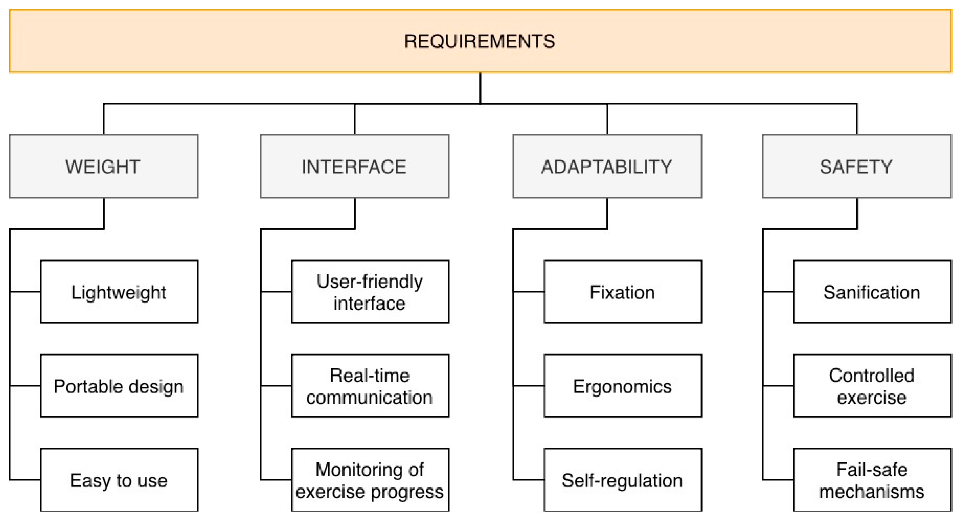
Figure 1. Main requirements for assisting device L-CADEL v5.
Designs 09 00126 g001
Figure 2. Conceptual design for L-CADEL v5 with connection to the web interface.
Designs 09 00126 g002
Figure 3. Conceptual design of the wrist platform for L-CADEL v.5.
Designs 09 00126 g003
Figure 4. The mechanical design of the wrist platform for L-CADEL v.5: (a) 3D CAD model and (b) prototype attached to a wrist.
Designs 09 00126 g004
Figure 5. Arm platform for L-CADEL v.5: (a) conceptual design; (b) circuit design.
Designs 09 00126 g005
Figure 6. The mechanical design of the arm platform for L-CADEL v.5: (a) 3D CAD model and (b) assembly prototype (1, 2: cables with hooks; 3, 4: covers of pulleys; 5: PCB board).
Designs 09 00126 g006
Figure 7. Shoulder support of the arm platform for L-CADEL v.5: (a) strap frame; (b) plastic base with lock and (c) stainless steel buckle with back patch.
Designs 09 00126 g007
Figure 8. Wearing the arm platform for L-CADEL v.5 on the user’s arm: (a) plastic base fixed on the tape of the shoulder support strap; (b) the process of attaching a steel buckle to a plastic base and (c) prototype attached to the user’s arm.
Designs 09 00126 g008
Figure 9. Control unit for L-CADEL v.5: (a) conceptual design; (b) 3D CAD model with instrumented cover and (c) PCB board.
Designs 09 00126 g009
Figure 10. Circuit design of control unit for L-CADEL v.5.
Designs 09 00126 g010
Figure 11. Scheme of connection Dynamixel servomotor to microcontroller, as in Figure 10.
Designs 09 00126 g011
Figure 12. Windows of the display interface of the control unit for L-CADEL v.5: (a) check elements of the system; (b) setting setup; (c) catalog of exercises; (d) exercise with data in real-time and (e) Wi-Fi network.
Designs 09 00126 g012
Figure 13. The designed web interface: (a) main elements and (b) structure scheme.
Designs 09 00126 g013
Figure 14. The designed web interface for users: (a) main elements and (b) client–server model.
Designs 09 00126 g014
Figure 15. The designed web interface for physiotherapists: (a) main elements; (b) scheme for plotting a figure.
Designs 09 00126 g015
Figure 16. HTTPS communication between client and server.
Designs 09 00126 g016
Figure 17. Testing layout with L-CADEL v5 prototype: (a) conceptual design and (b) lab setup (1: wrist platform; 2: arm platform; 3: shoulder support strap; 4: control unit and 5: laptop for web interface).
Designs 09 00126 g017
Figure 18. Snapshots of flexion–extension exercise by a volunteer for elbow testing device L-CADEL v5: (a) initial position (full extension); (b) half of the trajectory of flexion; (c) full flexion; (d) half of the trajectory of extension and (e) final position (full extension).
Designs 09 00126 g018
Figure 19. Acquired data during a test with L-CADEL.v5 prototype, as in Figure 19, displayed in the web interface in terms of: (a) pitch and roll angles and (b) acceleration components from IMU sensor.
Designs 09 00126 g019
Figure 20. Acquired data during a test with L-CADEL.v5 prototype, as in Figure 19, in terms of pitch and roll angles.
Designs 09 00126 g020
Figure 21. Acquired data during a test with L-CADEL.v5 prototype, as in Figure 19, in terms of acceleration components ax, ay, az and module.
Designs 09 00126 g021
Figure 22. Acquired data during a test with L-CADEL.v5 prototype, as in Figure 19, in terms of power consumption.
Designs 09 00126 g022
Table 1. Evolution of L-CADEL versions.
Characteristics/
Version
V1V2V3V4V5
Year/
location
2016/Cassino2019/Rome2020/Padova2024/Rome2025/Rome
Number of
platforms
33323
Number of
microcontrollers
22211
Number of
actuators
43222
Number of
cables
42222
Weight of
platforms
2.5 kg1.0 kg0.8 kg0.5 kg0.2 kg
Main improvementsOriginal
design [30]
Inflatable
interface with elbow-guided
cable [31]
Lightweight rings
and actuators [32]
Full autonomy,
two platforms,
one controller,
save data in SD
Lightweight rings,
Dymanixel AX-12A,
Wi-Fi communication
with web interface
Table 2. Cost analysis for components used for development of the L-CADEL v.5 prototype.
ComponentsQuantityUnit Cost (EUR)Total (EUR)
Microcontroller [35]110.0010.00
TFT Display 3.5 [36]110.0010.00
DYNAMIXEL AX-12A [34]275.00150.00
IMU sensor MPU 6050 [37]12.002.00
Shoulder support [38]14.004.00
Strap 20 mm wide12.002.00
Rechargeable 9 V Battery13.003.00
TOTAL180 EUR
Disclaimer/Publisher’s Note: The statements, opinions and data contained in all publications are solely those of the individual author(s) and contributor(s) and not of MDPI and/or the editor(s). MDPI and/or the editor(s) disclaim responsibility for any injury to people or property resulting from any ideas, methods, instructions or products referred to in the content.