Abstract
Because of its numerous advantages, 3D printing is widely employed for a variety of purposes. The mechanical characteristics of 3D-printed items are quite important. 3D-printed polylactic acid (PLA) is a common thermoplastic polymer due to its excellent characteristics and affordable cost. Because of its enhanced characteristics, polyethylene terephthalate glycol (PETG) has recently received a lot of attention. Despite PETG’s potential appeal in the 3D-printing field, little research has been conducted to explore its qualities, such as the impacts of raster angle on elasticity, which could lead to the development of more accurate guidelines for inspection and assessment. In this regard, this study examines the mechanical characteristics of polylactic acid (PLA) and polyethylene terephthalate glycol (PETG) 3D-printing specimens with different raster angles. Test specimens with raster angles of 15° and 30° were printed, and the stress–strain responses were recorded and compared with the simulated profiles generated using ANSYS software. The results showed that the raster angle significantly affected the mechanical properties of both types of materials. The simulated profile matched well with the experimental profile only in the case of PLA printed with a raster angle of 15°. These findings imply that extra effort should be made to ensure that the raster angle is tailored to yield the optimal mechanical properties of 3D-printed products.
1. Introduction
The process of additive manufacturing (AM), commonly known as 3D printing, has grown in popularity over the last decade due to its adaptability in generating a wide range of items with complicated geometries and unique mechanical qualities at a cheap cost. The development in the availability of 3D printers and the affordability of printing materials has fueled the rise in the use of 3D printing in recent years [1]. It is a technology that allows for the fabrication of parts with complicated geometry by creating them layer by layer on an optimized platform using computer-aided manufacturing and design. This technology is capable of printing almost any material (e.g., biological materials, polymers, ceramics, alloys and metals, etc.), allowing for a diverse range of products in engineering applications such as aerospace, civil engineering, biomedical, and automotive sectors [1,2,3]. One critical aspect that influences the performance of 3D-printed objects is their mechanical properties [4]. However, there is still a limited understanding of how different 3D-printing parameters affect these mechanical properties [5,6,7].
One of the reasons for the complexity in studying the mechanical properties of 3D-printed objects is the presence of complex microstructures. Due to the layer-by-layer nature of the additive manufacturing process, these objects often exhibit intrinsic anisotropic mechanical behavior. Anisotropy means that the mechanical properties can vary depending on the direction in which the object is tested. Additionally, numerous process factors, such as printing speed, temperature, and material composition, further influence the resulting mechanical properties. To overcome these challenges and gain insights into the structural performance of 3D-printed objects, computational modeling techniques are commonly employed [8]. In this regard, a finite element analysis (FEA) is used as a tool; it represents a powerful computational modeling approach used to simulate the mechanical behavior of complex structures, including those produced through additive manufacturing. This tool can be used in 3D-printing parameters, for which the raster angle is regarded as one of the 3D-printing parameters; it has been identified as a critical variable affecting the mechanical properties of printed objects [9,10,11]. The raster angle refers to the orientation of the printed layers with respect to the direction of printing. By changing the raster angle, the distribution of stresses and strains within the printed object can be altered, leading to variations in its mechanical behavior.
In the context of examining the mechanical properties of 3D-printed objects, two commonly used filament materials are polylactic acid (PLA) and polyethylene terephthalate glycol (PETG). PLA is a thermoplastic material known for its high tensile strength and stiffness [12,13]. PETG is another prominent filament material used in 3D printing [14]. Understanding the mechanical response of these materials after 3D printing at various raster angles is crucial for assessing their usability in different applications [15,16]. A previous study has demonstrated that the raster direction, thickness of layers, and temperature of the nozzle are the primary process parameters determining mechanical qualities [17,18]. It was also discovered that, additional to the previously discussed printing variables, the color of the filament, infill type, building orientation, and printing direction all have a significant impact on the tensile properties of PLA parts [19,20]. In this regard, therefore, it is noted that there are few recent studies that provided a study of the mechanical properties, especially for 3D-printed objects using PLA or PETG. Hanon, M.M. et al. [21] investigated the influence of the raster angle on the mechanical properties of 3D-printed objects using PLA and PETG. They focused on several key features of the 3D-printed standard tensile test samples, including stiffness, strength, and ultimate tensile strength. They aimed to understand how the raster angle affected these properties for both materials. Additionally, they performed FEA simulations to compare the simulated response with the experimental results [21]. Cocovi-Solberg, D.J. et al. [22] presented a measuring and analysis of the mechanical properties, including stiffness, strength, and ultimate tensile strength by conducting experimental tests on the 3D-printed samples. These tests were conducted at different raster angles to investigate the influence of orientation on the mechanical behavior of the printed objects. The data obtained from the experiments provided insights into the material’s response and helped establish correlations between the raster angle and mechanical properties. Several suggested models are proposed to replicate the geometry and material properties. In this regard, Abbot, D. et al. [23] developed finite element models that replicated the geometry and material properties of the printed samples. These models were used to simulate the mechanical response of objects under various loading conditions. By varying the raster angle in the simulation, this study studied and analyzed how the mechanical properties changed. Comparing the simulated responses with the experimental results allowed for the validation and refinement of the computational models. Due to the demonstration of the effectiveness of the recently developed integration approaches, numerical scenarios involving elastic fracturing using extended finite element approaches are presented and proven to be effective [24].
Another study gave valuable information on the influence of the raster angle on the mechanical properties of 3D-printed objects using PLA and PETG. The results indicated that the raster angle played a significant role in determining the stiffness, strength, and ultimate tensile strength (UTS) of the printed samples. The FEA simulations demonstrated good agreement with the experimental data, reinforcing the accuracy and reliability of the computational models [16]. Galeja, M. et al. [25] contributed to the study of the effect of different 3D-printing parameters, especially the raster angle, on the mechanical properties of 3D-printed objects. For example, by selecting an appropriate raster angle, it may be possible to enhance the strength and stiffness of printed objects in desired directions, making them more suitable for applications where mechanical performance is critical. Due to the importance of studying the different raster angle, especially due to its effect on the mechanical properties of three dimensional printing, Skhandesh, S. et al. [26] studied the effects of raster angle on the mechanical properties, which were investigated in seven orientations θ: 0°, 15°, 30°, 45°, 60°, 75°, and 90°. This study used commercially available SCFR-ABS and a consumer-grade FFF 3D printer; specimens of fracture toughness, flexure, and tensile were manufactured. This study concluded that the change in θ from 0° to 15° reduced tensile strength and flexural strength. Another study examined and contrasted the mechanical characteristics of PETG with those of PLA and ABS, two well-known FDM materials. To examine the impact of five distinct raster angle orientations on mechanical qualities, a total of 75 tensile tests were conducted. The findings of this inquiry will be used to make suggestions for using PETG material in 3D printing that is suitable for the intended design and application. This could lead to more precise reference data for prospective manufacturing technology applications [27]. E. Soleyman. et al. [28] proposed a new shape memory polymer (SMP) for the first, which exhibits high controlled self-coiling and stress-shaped memory behaviors in 3D printable PETG thermoplastic constructions. The outcomes demonstrated that the first printed layer contains the majority of the PETG’s pre-strain caused by printing. The wall impact experiment showed that raising the wall size weakens the shape transformation associated with the infill pattern. In addition, another study was presented to precisely resolve the underlying fourth-order complex differential equations (PDE) in linear elastic fracture mechanism (LEFM) issues, and a reliable Bezier-based multi-step technique was developed. The study’s findings revealed that GnPs with the highest aspect ratio are best for enhancing the plate’s elastic characteristics and may be preventing the spread of edge cracks [29].
Starting with recent research information, which is frequently marred by ambiguity concerning the influence of specific process parameters on the mechanical characteristics [19,30], additionally, most recent research has presented poor results on the effects of raster angle on the elasticity of 3D-printed polylactic acid and polyethylene terephthalate glycol. So, the field remains open for more research studies on this point because additive manufacturing has revolutionized various industries, offering new possibilities for rapid prototyping and functional applications. Additionally, studying the mechanical properties of 3D-printed objects significantly impacts their functional behavior and overall performance. However, the influence of different 3D-printing parameters on these properties, including the raster angle, is still not fully understood. In this regard, this study presents computational modeling using finite element analysis, combined with experimental testing, provides an effective approach to evaluate the structural performance of 3D-printed objects. In addition, it presents an examination of the effect of the raster angle on the mechanical properties, such as stiffness, strength, and ultimate tensile strength, that contribute to the understanding of material behavior and facilitate the optimization of printing parameters for specific applications.
2. Methodology
Using the universal test machine (UTM) as in Figure 1a, according to the requirements of the American Society for Materials and Testing standard, the tensile specimens were developed, processed, and printed in a flat dogbone shape. The shapes were examined in accordance with the Test Procedures for Tensile Properties of Plastics (ASTM D638) [31], a standard for plastic specimens. To investigate the influence of the raster angle on the mechanical properties of 3D-printed objects, standard tensile test samples were fabricated using a 3D printer. The generic type of filament fiber in 3D printing (PLA) is used in this study. The materials chosen for this study were polylactic acid (PLA) and polyethylene terephthalate glycol (PETG). The printing angles selected were 15° and 30°.
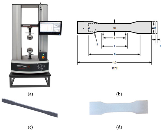
Figure 1.
(a) Universal test machine, (b) dimensions and shape of test sample, (c) the SolidWorks dogbone sample, and (d) the dogbone sample in CURA.
The dimensions of the test samples were determined based on the requirements of the standard tensile test. These dimensions, including length, width, and thickness. It is important to ensure that the samples meet the specifications of the standard test to ensure accurate and comparable results.
To evaluate the mechanical properties of the printed samples, the ANSYS program was employed. ANSYS is widely used finite element analysis (FEA) software that allows for the simulation of mechanical behavior in complex structures. The use of the ANSYS program in this study allowed for a comprehensive analysis of the mechanical properties of the 3D-printed samples. It provided a means to predict and visualize the behavior of the samples under different loading conditions, enabling a deeper understanding of the influence of the raster angle on their performance. The program uses numerical methods to solve the governing equations and predict the response of the structure to external loads. Using the ANSYS program, simulation curves for the tensile test samples were generated. These simulation curves represented the expected mechanical behavior of the printed samples under different loading conditions. By varying the raster angle in the simulations, the effect of this parameter on the mechanical properties of the objects was studied. Using software for finite element analysis, the simulation was carried out. The same steps are used in all finite element analyses. The software used for FEA (finite element analysis) is called ANSYS Workbench Explicit. The CAD (computer-aided design) model, which is prepared for analysis and broken-down during splicing (differentiating into smaller pieces), is an important aspect of FEM. The calibration test simulation is carried out in order to compare the findings of the simulation and experiment in order to validate the simulation results.
The simulation curves provided valuable insights into how the mechanical properties, such as stiffness, strength, and ultimate tensile strength, varied with the printing angles of 15° and 30°. By comparing the simulation results with the experimental data obtained from testing the fabricated samples, the accuracy of the computational models can be validated.
Dynamic explicit/implicit in Ansys with a fixed support on the bottom of the sample as a boundary condition and another boundary condition with a displacement support on the top of the PLA and PETG samples were used.
In this study, dogbone tensile test samples were used to evaluate the mechanical properties of the 3D-printed objects. The dogbone geometry, specified by the ASTM D638 standard [31], was employed for its well-established design and suitability for measuring the tensile characteristics of both reinforced and unreinforced polymers [32]. When tested under specific preparation, humidity, temperature, and testing machine speed conditions, typical dumbbell-shaped test specimens used in ASTM D638 can be used to determine the tensile strength of both reinforced and unreinforced plastic. The procedures using ASTM D638 are as follows:-
- Each specimen’s length and thickness should be measured to the nearest 0.025 mm (0.001 in.);
- Put the sample in the test machine’s grips while being careful to line up their long axes with an imaginary line connecting the grips’ connection points to the machine;
- Turn on the machine, noting the specimen’s load-extension curve, the load and extension at the yield point (if one exists), and the pressure and extension at the point of rupture;
- Screw on the extension indication;
- Sett the testing speed to the appropriate rate and start the machine;
- Record the specimen’s load-extension curve and extension at the yield point.
The dogbone geometry features shoulder sections at both ends of the sample, connected by a narrower gauge section. The shoulders are wider than the gauge section, resulting in a stress concentration in the middle when the sample is subjected to tensile forces. This stress concentration amplifies the likelihood of sample rupture, making it a favorable configuration for determining the ultimate tensile strength of the material.
During the tensile test, the sample is clamped at the shoulders, and an axial force is applied to the gauge section until it fractures. When the sample ruptures in the middle of the gauge section, it indicates that the material has reached its ultimate tensile strength. However, if the failure occurs at one of the ends or in the grip region, it suggests that improper loading or preexisting flaws in the material may be responsible for the failure.
By utilizing the dogbone geometry, this testing methodology ensures the highest probability of failure due to the ultimate tensile load. ASTM D638 type I is the most widely adopted standard for measuring the tensile properties of both reinforced and unreinforced polymers. It provides guidelines for sample dimensions, specimen preparation, testing conditions, and result calculations [32].
Figure 1 and Figure 2 depict the dimensions and shapes of the 3D-printed test specimens used in the study. The specimens are 4 mm thick with an 85 mm gauge length. Figure 1 depicts more geometries and measurements. Figure 1 and Figure 2 illustrate the specific geometry of the dogbone samples, including the overall length, shoulder width, gauge length, and thickness. Adhering to the ASTM D638 standard and using a dogbone design enables the reliable and consistent testing of the mechanical properties of the 3D-printed objects. Printing parameters can be tabulated as a wall, and the top and bottom thicknesses are 2 and 0.8 mm, respectively (See Table 1). The tabulated dimensional parameters are 13 mm for W—width and 57 mm for L—length of the narrow section. Overall, width and length are 19 and 165 mm, respectively, according to Table 2.
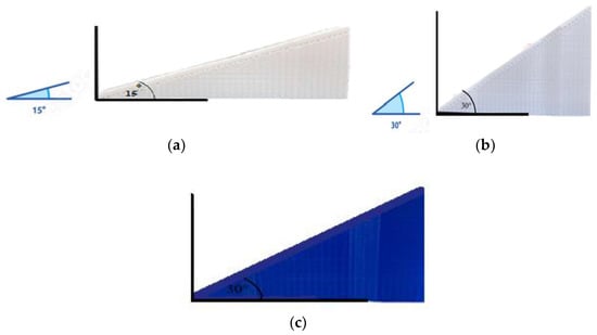
Figure 2.
(a) Dogbone sample 15 degree for PLA/PETG, (b) dogbone sample 30 degree for PETG, and (c) dogbone sample 30 degree for PLA.

Table 1.
Printing parameters.
Table 2.
Printing dimensional parameters.
By employing the dogbone tensile test samples, this study aimed to evaluate the mechanical behavior of the 3D-printed objects under tensile loading. The standardized geometry and testing procedure allow for meaningful comparisons and provide valuable insights into the material’s tensile strength, stiffness, and other mechanical properties. The elastic modulus calculated in this study uses the slope approach.
3. Results and Discussion
3.1. Experimental Results of PLA
In this study, the mechanical properties of PLA filaments were thoroughly investigated, with a focus on the impact of different printing angles on these properties. Stress-relieving heat treatment was used to establish a uniform temperature distribution during the printing process. Initially, it was found that PLA filaments exhibited high strength but limited ductility, as evidenced by the data presented in Table 3. To address this limitation, the effects of printing angles of 15° and 30° on the ductility of PLA can be explored. The data presented in Table 3 are the best sample measured. As shown in this table, the densities (g/cm3) were 1.24, 1.24, 1.28, and 1.28; the elasticities (MPa) were 191.23, 111.66, 56.17, and 52.9; and the maximum tensile strengths (MPa) were 25.53, 5.73, 4.484, and 8.39, for PLA 15°, PLA 30°, PETG 15°, and PETG 30°, respectively.
Table 3.
Mechanical properties for PLA and PETG samples.
Upon conducting the tensile tests, several key observations were made. The sample printed at a 15° angle exhibited reduced stiffness compared to the original material. This indicates that printing at this angle led to a more pliable structure, which is advantageous in applications requiring flexibility. Additionally, the 15° print angle resulted in the improved strength and higher elasticity of the PLA material. The enhanced strength implies a greater ability to withstand applied loads, while the increased elasticity suggests improved deformability under stress.
In contrast, the PLA samples printed at a 30° angle exhibited a distinct mechanical behavior. Notably, the material displayed higher elasticity and flexibility, which led to failure occurring before reaching the yield point. This is illustrated by the linear stress–strain profile observed throughout the entire range in Figure 3. The 30° print angle enhanced the PLA’s ability to deform without permanent damage, indicating its suitability for applications where flexibility and resilience are desired.
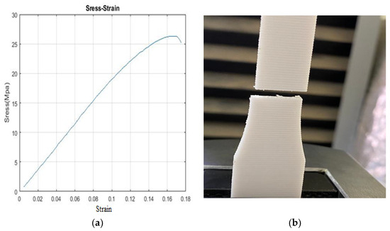
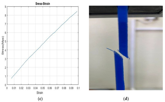
Figure 3.
Mechanical properties of the 3D-printed specimen: (a) stress–strain profile for PLA 15°, (b) photograph of a failed 3D-printed PLA 15° specimen sample, (c) stress–strain profile for PLA 30°, and (d) photograph of a failed 3D-printed PLA 30° specimen.
The results emphasize the significant influence of print angle on the mechanical properties of PLA. By altering the angle, it is possible to tailor the material’s stiffness, elasticity, strength, and ductility to meet specific application requirements. These findings provide valuable insights for optimizing the 3D-printing process and achieving desired mechanical properties in PLA-based objects.
It is important to note that the study’s outcomes are focused specifically on PLA filaments and their response to different printing angles. While PLA is a widely used material, other factors such as filament composition, printing parameters, and post-processing techniques may also impact the final mechanical properties of 3D-printed objects. Further research is needed to explore these aspects and expand our understanding of how different materials and printing conditions interact to influence the mechanical behavior of printed objects.
Overall, the findings underscore the potential of utilizing various printing angles as a means of tailoring the mechanical properties of 3D-printed PLA objects. This knowledge can guide the design and fabrication of PLA-based components in diverse fields, including biomedicine, aerospace, and consumer goods, where specific mechanical characteristics are crucial for optimal performance.
3.2. Simulation Results of PLA
The ANSYS program has been used to simulate the stress–strain response of the dogbone specimens and compare the experimental results with the simulation curves. Regarding the interface ANSYS tensile test for meshing, and element size of 0.0009 was used to obtain adequate meshing; for boundary conditions, explicit dynamics were used by employing fixed support and the steps of using subroutines in ANSYS. This analysis aimed to investigate the relationship between the printing angle and the mechanical behavior of the samples.
Figure 4 presents the experimental curves for each sample, which closely aligned with the simulation curves associated with their respective printing angles. This close match between the experimental and simulated responses allowed one to obtain a clear understanding of how different printing angles affected the mechanical properties of the samples. Notably, a significant difference was observed when the printing angle was varied.
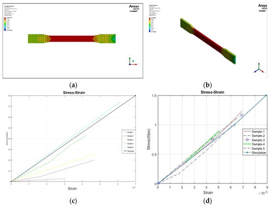
Figure 4.
(a) Simulation for PLA, (b) simulation for PLA (3D), (c) stress–strain results chart of PLA−15° experimental/simulation, and (d) stress–strain results chart of PLA−30° experimental/simulation.
For the PLA samples printed at a 15° angle, notable improvements in mechanical properties were observed. These improvements included enhanced ductility, flexibility, and strength [28]. Moreover, the experimental results of these samples closely resembled the simulation curve, indicating good agreement between the experimental and simulated responses, with the exception of sample 2. This suggests that the mechanical properties of PLA printed at a 15° angle were predictable and consistent with the predictions from the simulation.
In contrast, the PLA samples printed at a 30° angle exhibited a reduction in certain mechanical properties, particularly in terms of ductility. These samples were more brittle and showed a noticeable decrease in strength and elasticity. However, it is important to note that the experimental results for these samples were not entirely valid as only two of them matched the simulation curve [29]. This discrepancy between the experimental and simulated results suggests a deviation from the expected behavior, potentially due to other influencing factors or variations in the printing process.
The findings derived from the comparison between the experimental and simulated results further highlight the significance of the printing angle in influencing the mechanical properties of PLA samples. The PLA printed at a 15° angle demonstrated improved performance, whereas the 30° printing angle led to a reduction in certain mechanical properties. These results provide valuable insights into how adjusting the printing angle can affect the final mechanical behavior of 3D-printed PLA objects, underscoring the importance of considering this parameter when aiming to achieve desired material properties.
It is important to acknowledge that the experimental and simulated results presented in this study focused specifically on PLA samples and their response to different printing angles. Other factors such as filament composition, printing parameters, and post-processing techniques could also impact the final mechanical properties of 3D-printed objects. Therefore, it is crucial to conduct further research to explore these factors and gain a comprehensive understanding of their influence on the mechanical behavior of printed objects.
The findings from this study provide valuable insights into the relationship between the printing angle and the mechanical properties in PLA samples. By adjusting the printing angle, it is possible to tailor the mechanical behavior of 3D-printed PLA objects to meet specific application requirements. These insights contribute to the optimization of the 3D-printing process and the production of PLA-based components with desired mechanical characteristics in various fields, including biomedicine, aerospace, and consumer goods.
3.3. Experimental Results of PETG
The mechanical properties of the PETG filament materials were compared with PLA in this study, and it was found that PETG exhibited greater strength [30]. The experimental results for the two different printing angles, 15° and 30°, were analyzed to understand their impact on the mechanical properties of PETG. Figure 5 illustrates the findings, showing improvements in the mechanical properties of the samples printed at a 30° angle.
Figure 5.
Mechanical properties of the 3D-printed specimen: (a) stress–strain profile for PETG 15°, (b) photograph of a failed 3D-printed PETG 15° specimen sample, (c) stress–strain profile for PETG 30°, and (d) photograph of a failed 3D-printed PETG 30° specimen.
The PETG samples printed at a 30° angle demonstrated higher strength than those printed at a 15° angle. Additionally, there was a slight increase in stiffness and a reduction in ductility and flexibility for the 30° samples. This indicates that the printing angle significantly influenced the mechanical behavior of PETG, affecting its strength, stiffness, ductility, and flexibility. The samples printed at a 30° angle exhibited improved the overall mechanical performance.
On the other hand, the experimental results for the PETG samples printed at a 15° angle indicated slightly increased ductility and elasticity compared to the 30° samples. This suggests that a lower printing angle can lead to enhanced ductility and elasticity in PETG. However, it is important to note that the improvements in these properties were not as significant as the gains observed in strength and stiffness for the samples printed at a 30° angle.
These findings provide valuable insights into how adjusting the printing angle can optimize the mechanical properties of 3D-printed PETG objects for different applications. By selecting an appropriate printing angle, it is possible to enhance the strength and stiffness of PETG, which may be desirable in applications where structural integrity is crucial. However, if improved ductility and flexibility are the main requirements, a lower printing angle such as 15° may be more suitable.
It is important to consider that other factors, such as filament composition, printing parameters, and post-processing techniques, can also influence the mechanical properties of 3D-printed PETG objects. Therefore, further research is needed to investigate the combined effects of these factors along with the printing angle to fully understand their impact on the mechanical behavior of PETG.
The insights gained from this study provide guidance for optimizing the 3D-printing process and producing PETG-based components with tailored mechanical properties. This knowledge can be valuable in various industries, including automotive, aerospace, and consumer goods, where PETG’s strength and other mechanical characteristics play a crucial role in the performance and durability of printed objects.
3.4. Simulation Results of PETG
The sample printed at a 15° angle demonstrated a slight decrease in stiffness and ductility compared to the original material. However, it is important to acknowledge that the experimental results for this particular sample were not entirely reliable as only one sample closely aligned with the simulation curve, while the remaining samples exhibited significant deviations, as depicted in Figure 6.
Figure 6.
(a) Simulation for PETG, (b) simulation for PETG (3D), (c) stress–strain results chart of PETG −15° experimental/simulation, and (d) stress–strain results chart of PETG −30° experimental/simulation.
Despite the limitations in the experimental results, it is still possible to observe some trends in the mechanical properties of the sample printed at a 15° angle. The findings indicate that this printing angle resulted in improvements in strength and stiffness compared to the original material. This suggests that altering the printing angle can have a discernible impact on enhancing the mechanical properties of the printed samples.
Additionally, there were reductions in ductility and flexibility observed for the sample printed at a 15° angle. These changes in mechanical behavior indicate that the printing angle can influence the material’s response to applied loads and its ability to deform without fracturing. By modifying the printing angle, it is possible to achieve different combinations of mechanical properties that align with the requirements of specific applications.
However, it is crucial to acknowledge the limitations of the experimental results as the majority of the samples printed at a 15° angle deviated significantly from the simulated profile. This discrepancy between the experimental and simulated responses suggests potential factors influencing the mechanical behavior that were not accounted for or variations in the printing process.
To gain a comprehensive understanding of the impact of the 15° printing angle on the mechanical behavior of the printed objects, further investigation and analysis are warranted. It is necessary to conduct a more extensive experimental study with a larger sample size to obtain reliable and statistically significant results. Moreover, additional factors such as printing parameters, material composition, and post-processing techniques should be considered to elucidate their contributions to the observed mechanical properties.
By conducting thorough investigations and addressing the limitations, authors can refine their understanding of the influence of the 15° printing angle and potentially optimize the printing parameters to achieve desired mechanical properties in future 3D-printed objects. This knowledge can pave the way for the development of tailored materials and structures with improved mechanical performance for various applications. The results in Figure 4 and Figure 6, which indicate the simulation of PETG and PLA, were based on the difference in the raster angle.
4. Conclusions
The aim of this research is to complement previous research in the field of 3D printers; therefore, this research has presented the effects of raster angle on the elasticity of 3D-printed polylactic acid and polyethylene terephthalate glycol. These printing angles were 15° and 30°. Accordingly, this study has provided valuable insights into the significant impact of the raster angle on the mechanical properties of 3D-printed PLA and PETG materials. By manipulating the printing angles to 15° and 30° for PLA and PETG, respectively, notable improvements were observed in the mechanical characteristics of these materials using the simulated profiles generated using ANSYS software. This study concluded that
- The specimens are 60% solid, which is the infill for the rest of the infilling; this is the primary reason for anisotropy.
- For PLA, the samples printed at a 15° angle exhibited enhancements in strength, elasticity, and flexibility, while experiencing a slight reduction in stiffness compared to the original material. These findings suggest that the 15° printing angle optimized the mechanical properties of PLA, making it more suitable for applications where increased strength and flexibility are desired.
- In the case of PETG, the samples printed at a 30° angle showed improvements in strength, elasticity, and flexibility. However, there was a reduction in ductility compared to the original material. These findings suggest that the 30° printing angle optimized the mechanical properties of PETG, making it more suitable for applications where increased strength and flexibility are desirable.
Generally, this study emphasizes the criticality of carefully optimizing 3D-printing parameters, particularly the raster angle, to achieve the desired mechanical properties of printed PLA and PETG objects. These findings highlight the complexity of the 3D-printing process and underscore the need for further research to fully comprehend and control the mechanical behavior of printed materials. Such insights are essential for guiding the design and fabrication of 3D-printed objects across diverse fields, including biomedicine, aerospace, and automotive engineering, where tailored mechanical properties are of utmost importance.
Continued investigations into the effects of printing parameters, material compositions, and post-processing techniques will contribute to a deeper understanding of the relationships between 3D-printing parameters and mechanical behavior. This knowledge can further facilitate the development of advanced 3D-printing strategies, enabling the production of customized objects with optimized mechanical properties to meet the specific requirements of various applications.
This study examines the mechanical characteristics of polylactic acid (PLA) and polyethylene terephthalate glycol (PETG) 3D-printing specimens with 15° and 30° raster angles only. This allows the field to study the mechanical characteristics of polylactic acid (PLA) and polyethylene terephthalate glycol (PETG) 3D-printing specimens at other different angles.
Supplementary Materials
The following supporting information can be downloaded at: https://www.mdpi.com/article/10.3390/designs7050112/s1, Figure S1: The steps of using subroutines in ANSYS.
Funding
This research received no external funding.
Institutional Review Board Statement
Not applicable.
Data Availability Statement
Data is contained within the article or Supplementary Materials. The datasets used during the current study are available from the corresponding author on reasonable request.
Acknowledgments
The author would like to thank the Deanship of Scientific Research, Qassim University for funding the publication fee of this project.
Conflicts of Interest
The author declares no conflict of interest. The funders had no role in the design of the study; in the collection, analyses, or interpretation of data; in the writing of the manuscript; or in the decision to publish the results.
References
- Albadrani, M.A. Failure Prediction in 3D Printed Kevlar/Glass Fiber-Reinforced Nylon Structures with a Hole and Different Fiber Orientations. Polymers 2022, 14, 4464. [Google Scholar] [CrossRef] [PubMed]
- Mohanavel, V.; Ashraff Ali, K.S.; Ranganathan, K.; Allen Jeffrey, J.; Ravikumar, M.M.; Rajkumar, S. The roles and applications of additive manufacturing in the aerospace and automobile sector. Mater. Today Proc. 2021, 47, 405–409. [Google Scholar] [CrossRef]
- Rahmatabadi, D.; Aberoumand, M.; Soltanmohammadi, K.; Soleyman, E.; Ghasemi, I.; Baniassadi, M.; Abrinia, K.; Zolfagharian, A.; Bodaghi, M.; Baghani, M. A New Strategy for Achieving Shape Memory Effects in 4D Printed Two-Layer Composite Structures. Polymers 2022, 14, 5446. [Google Scholar] [CrossRef] [PubMed]
- Rahmatabadi, D.; Soltanmohammadi, K.; Aberoumand, M.; Soleyman, E.; Ghasemi, I.; Baniassadi, M.; Abrinia, K.; Bodaghi, M.; Baghani, M. Development of Pure Poly Vinyl Chloride (PVC) with Excellent 3D Printability and Macro- and Micro-Structural Properties. Macromol. Mater. Eng. 2023, 308, 2200568. [Google Scholar] [CrossRef]
- Abeykoon, C.; Sri-Amphorn, P.; Fernando, A. Optimization of fused deposition modeling parameters for improved PLA and ABS 3D printed structures. Int. J. Lightweight Mater. Manuf. 2020, 3, 284–297. [Google Scholar] [CrossRef]
- Schwartz, J.J.; Hamel, J.; Ekstrom, T.; Ndagang, L.; Boydston, A.J. Not all PLA filaments are created equal: An experimental investigation. Rapid Prototyp. J. 2020, 26, 1263–1276. [Google Scholar] [CrossRef]
- Lee, D.; Wu, G.-Y. Parameters Affecting the Mechanical Properties of Three-Dimensional (3D) Printed Carbon Fiber-Reinforced Polylactide Composites. Polymers 2020, 12, 2456. [Google Scholar] [CrossRef]
- Rahmatabadi, D.; Soltanmohammadi, K.; Pahlavani, M.; Aberoumand, M.; Soleyman, E.; Ghasemi, I.; Baniassadi, M.; Abrinia, K.; Bodaghi, M.; Baghani, M. Shape memory performance assessment of FDM 3D printed PLA-TPU composites by Box-Behnken response surface methodology. Int. J. Adv. Manuf. Technol. 2023, 127, 935–950. [Google Scholar] [CrossRef]
- Ezeh, O.H.; Susmel, L. Fatigue strength of additively manufactured polylactide (PLA): Effect of raster angle and non-zero mean stresses. Int. J. Fatigue 2019, 126, 319–326. [Google Scholar] [CrossRef]
- Rajpurohit, S.R.; Dave, H.K. Flexural strength of fused filament fabricated (FFF) PLA parts on an open-source 3D printer. Adv. Manuf. 2018, 6, 430–441. [Google Scholar] [CrossRef]
- Gonabadi, H.; Chen, Y.; Yadav, A.; Bull, S. Investigation of the effect of raster angle, build orientation, and infill density on the elastic response of 3D printed parts using finite element microstructural modeling and homogenization techniques. Int. J. Adv. Manuf. Technol. 2021, 118, 1485–1510. [Google Scholar] [CrossRef]
- Lyu, Y.; Chen, Y.; Lin, Z.; Zhang, J.; Shi, X. Manipulating phase structure of biodegradable PLA/PBAT system: Effects on dynamic rheological responses and 3D printing. Compos. Sci. Technol. 2020, 200, 108399. [Google Scholar] [CrossRef]
- Yonezawa, A.; Yamada, A. Deterioration of the mechanical properties of FFF 3d-printed PLA structures. Inventions 2020, 6, 1. [Google Scholar] [CrossRef]
- Ajay Kumar, M.; Khan, M.S.; Mishra, S.B. Effect of machine parameters on strength and hardness of FDM printed carbon fiber reinforced PETG thermoplastics. Mater. Today Proc. 2020, 27, 975–983. [Google Scholar] [CrossRef]
- Yao, T.; Deng, Z.; Zhang, K.; Li, S. A method to predict the ultimate tensile strength of 3D printing polylactic acid (PLA) materials with different printing orientations. Compos. Part. B Eng. 2019, 163, 393–402. [Google Scholar] [CrossRef]
- Hsueh, M.H.; Lai, C.J.; Chung, C.F.; Wang, S.H.; Huang, W.C.; Pan, C.Y.; Zeng, Y.S.; Hsieh, C.H. Effect of Printing Parameters on the Tensile Properties of 3D-Printed Polylactic Acid (PLA) Based on Fused Deposition Modeling. Polymers 2021, 13, 2387. [Google Scholar] [CrossRef] [PubMed]
- Linul, E.; Marsavina, L.; Stoia, D.I. Mode I and II fracture toughness investigation of Laser-Sintered Polyamide. Theor. Appl. Fract. Mech. 2020, 106, 102497. [Google Scholar] [CrossRef]
- Stoia, D.I.; Marsavina, L.; Linul, E. Mode I fracture toughness of polyamide and alumide samples obtained by Selective Laser Sintering additive process. Polymers 2020, 12, 640. [Google Scholar] [CrossRef]
- Kiendl, J.; Gao, C. Controlling toughness and strength of FDM 3D-printed PLA components through the raster layup. Compos. Part B 2020, 180, 107562. [Google Scholar] [CrossRef]
- Yao, T.; Ye, J.; Deng, Z.; Zhang, K.; Ma, Y.; Ouyang, H. Tensile failure strength and separation angle of FDM 3D printing PLA material: Experimental and theoretical analyses. Compos. Part B 2020, 188, 107894. [Google Scholar] [CrossRef]
- Hanon, M.M.; Marczis, R.; Zsidai, L. Anisotropy evaluation of different raster directions, spatial orientations, and fill percentage of 3D printed PETG tensile test specimens. In Key Engineering Materials; Trans Tech Publ.: Schwyz, Switzerland, 2019. [Google Scholar]
- Cocovi-Solberg, D.J.; Worsfold, P.J.; Miró, M. Opportunities for 3D printed millifluidic platforms incorporating on-line sample handling and separation. TrAC Trends Anal. Chem. 2018, 108, 13–22. [Google Scholar] [CrossRef]
- Abbot, D.W.; Kallon, D.V.; Anghel, C.; Dube, P. Finite element analysis of 3D printed model via compression tests. Procedia Manuf. 2019, 35, 164–173. [Google Scholar] [CrossRef]
- Mousavi, S.E.; Sukumar, N. Generalized Gaussian quadrature rules for discontinuities and crack singularities in the extended finite element method. Comput. Methods Appl. Mech. Eng. 2010, 199, 3237–3249. [Google Scholar] [CrossRef]
- Galeja, M.; Hejna, A.; Kosmela, P.; Kulawik, A. Static and dynamic mechanical properties of 3D printed ABS as a function of raster angle. Materials 2020, 13, 297. [Google Scholar] [CrossRef] [PubMed]
- Skhandesh, S.; Ozgur, K. Effect of raster angle on mechanical properties of 3D printed short carbon fiber reinforced acrylonitrile butadiene styrene. Compos. Commun. 2022, 32, 101163. [Google Scholar]
- Sepahi, M.; Abusalma, H.; Jovanovic, V.; Eisazadeh, H. Mechanical Properties of 3D-Printed Parts Made of Polyethylene Terephthalate Glycol. J. Mater. Eng. Perform. 2021, 30, 6851–6861. [Google Scholar] [CrossRef]
- Soleyman, E.; Aberoumand, M.; Rahmatabadi, D.; Soltanmohammadi, K.; Ghasemi, I.; Baniassadi, M.; Abrinia, K.; Baghani, M. Assessment of controllable shape transformation, potential applications, and tensile shape memory properties of 3D printed PETG. J. Mater. Res. Technol. 2022, 18, 4201–4215. [Google Scholar] [CrossRef]
- Kabir, H.; Aghdam, M.M. A generalized 2D Bézier-based solution for stress analysis of notched epoxy resin plates reinforced with graphene nanoplatelets. Thin-Walled Struct. 2021, 169, 108484. [Google Scholar] [CrossRef]
- Heidari-Rarani, M.; Ezati, N.; Sadeghi, P.; Badrossamay, M.R. Optimization of FDM process parameters for tensile properties of polylactic acid specimens using Taguchi design of experiment method. J. Thermoplast. Compos. Mater. 2020, 35, 2435–2452. [Google Scholar] [CrossRef]
- Lachica, L. Making Dogbone Tensile Test Samples; TestResources: Shakopee, MN, USA, 2013. [Google Scholar]
- ASTM D638; Standard Test Method for Tensile Properties of Plastics. ASTM: West Conshohocken, PA, USA, 2022.
Disclaimer/Publisher’s Note: The statements, opinions and data contained in all publications are solely those of the individual author(s) and contributor(s) and not of MDPI and/or the editor(s). MDPI and/or the editor(s) disclaim responsibility for any injury to people or property resulting from any ideas, methods, instructions or products referred to in the content. |
© 2023 by the author. Licensee MDPI, Basel, Switzerland. This article is an open access article distributed under the terms and conditions of the Creative Commons Attribution (CC BY) license (https://creativecommons.org/licenses/by/4.0/).