Abstract
Smart charging management systems for electric vehicles (SCMSs) enable the effective management of electric vehicle (EV) charging processes using smart technologies. Numerous SCMS technologies have been available for different stakeholders, e.g., EV drivers, charging station managers, and car manufacturers. Despite the ever-increasing interest in SCMSs, the literature lacks in reusable, standardised architecture design that reduces the effort for the development of quality SCMSs. In this paper, we propose a reference architecture (RA) for SCMSs. Our RA design is based on our comprehensive domain analysis that encompasses the analysis of the existing literature and commercial technologies which have been supported by our survey on EV drivers. In our RA, we provide four different viewpoints. The context viewpoint classifies the potential stakeholders and their roles and responsibilities. The module viewpoint defines the software implementation units and their modules that can be used for implementing any SCMSs. The component and connector viewpoint defines the executing parts of any SCMSs and their organisations into layers. The allocation viewpoint defines how the executable components can be mapped into the physical devices. We validated our RA design via prototyping and surveying to measure the RA’s applicability in real-world scenarios and usability for stakeholders.
1. Introduction
Digital transformation leads a wide range of industries (e.g., automotive, manufacturing, logistics, and healthcare) to integrate smart solutions in their business activities for enhancing their business quality while optimising their resource consumption [1,2]. Thanks to smart digital technologies, industries can maximise their operational efficiency and release high-quality and sustainable products.
Many industries that have not been digitalised in the past (e.g., agriculture, education, transport and logistics, automotive, avionics, healthcare, and retail) are, nowadays, computerised and use diverse tools, techniques, and platforms through which they can automate their businesses and better achieve their goals [3,4]. The healthcare industry uses digital technologies for, e.g., remote consultations, AI-based diagnosis and treatment, wearable devices, and robotic surgery [5]. The manufacturing industry uses smart factories, digital twins, and predictive maintenance [6]. The agriculture industry uses precision farming, AI-based crop management, and robotics for farming [7]. The automotive industry uses connected vehicles, electric vehicles, autonomous driving, digital showrooms and sales, advanced driver-assistant systems, smart mobility, and in-car entertainment systems [8].
Digital transformation has gained an ever-increasing importance for the automotive industry in particular. Nowadays, over 50% of car manufacturing costs is due to digital technologies such as digital infotainment, battery management, and advanced driver assistance systems. The current trend for the automotive industry leads to cars that are electrified, autonomous, shared, and updated yearly, all of which require the application of innovative technologies. According to McKinsey’s Automotive Software and Electronics Benchmark, the total growth of automotive software and electronics is expected to exceed USD 462 billion by 2030. The advanced, innovative technologies here include (i) digital twins and AI technologies for the car conceptual design [9], (ii) smart systems for autonomous cars [10], (iii) smart car manufacturing processes [11], (iv) smart optimisations of the logistics and sales processes [12,13], and (v) other smart solutions for the automotive industry (e.g., smart systems for electric vehicle management, smart mobility, and infotainment systems) [14,15,16].
The rise of electric vehicles (EVs) has accelerated digital transformation in the automotive industry. Diverse smart systems have been developed to manage EVs effectively, such as battery management systems [17], energy management systems [18], charging management [19], and charging station management [20]. Additionally, EV technologies integrate with the existing software systems that control cars, any smart home technologies, and IoT technologies (e.g., sensors, cameras, etc.).
EV charging has been shown great interest by tool vendors. Numerous smart charging management systems (SCMSs) are available commercially, which automate the charging management processes and facilitate the decision-making processes with the use of advanced technologies such as artificial intelligence, big data analytics, internet of things, and cloud computing. SCMSs provide various facilities including charging monitoring, charging station management, charging station reservation, navigation to the charging station, online charging payment, administration, energy management, and smart home integration. SCMSs can be used by multiple different stakeholders, including EV drivers, charging station providers, administrators, energy providers, property managers, and even EV manufacturers, who perform various operations for their specific goals and interact with each other.
Given various complex features and multiple interacting stakeholders, SCMSs are inherently complex systems. Thus, it is highly crucial to follow an architecture-centric development approach for SCMSs to manage their complexity. With software architectures, different concerns for the development of SCMSs (e.g., stakeholders’ interactions with the system, system’s integration with the environment, logical structure, mapping logical components to physical elements, and the development structure) can be handled separately and the principal design decisions that are essential for meeting the system-level goals (e.g., performance, scalability, and reusability) can easily be addressed from different points of view. With software architecture-centric development, high-quality SCMSs can be developed with minimised time and budget in a way that can easily be maintained.
Our analysis reveals that while numerous SCMSs are available commercially (the list of commercial SCMS tools that we analysed for understanding their capabilities are reachable via: https://zenodo.org/records/15808275, accessed on 1 November 2025), the literature lacks generic and reusable architecture descriptions for SCMSs. As discussed in Section 2, the existing studies in the literature focus on (i) the user experience in EV smart charging, (ii) integration of electrical grids to EV charging, (iii) the optimisation algorithms for EV charging, (iv) the applications of advanced technologies (e.g., data analytics) for EV smart charging, (v) analytical studies on understanding the trends and challenges, and (vi) any tool demonstrations. However, the literature does not aid in understanding SCMSs from an architecture perspective, which includes (i) the stakeholders who can be involved in SCMSs and their roles and relationships with an SCMS, (ii) the mandatory and optional features for SCMSs, and (iii) the optimal structuring of SCMSs from different points of view that meet the desired features. Thus, this could make it difficult for tool vendors to estimate the project cost and develop high-quality SCMSs with minimum costs. Developers may not easily understand the big picture of their SCMSs which can increase their development costs, and researchers may not easily determine the technical challenges and conduct relevant researches. Lastly, end users (e.g., drivers, charging station managers, property managers, and energy providers) may not easily evaluate the quality of the SCMSs that they use in terms of the features supported (e.g., dynamic pricing, charging monitoring, etc.).
The purpose of this paper is to define and validate a reusable reference architecture (RA) that systematically represents the common structure, variability, and architectural concerns of SCMSs. In this paper, we proposed an RA that represents the generic and reusable design of software architectures for the SCMS product family. Our RA design describes all possible features that any SCMS can possess which are further decomposed into sub-features and categorised as being mandatory and optional. Our RA design for SCMSs supports four different viewpoints each of which deals with a different concern, which are the context viewpoint, module viewpoint, component and connector viewpoint, and allocation viewpoint. The context viewpoint describes stakeholders (e.g., driver, charging station managers, sensors, developers, etc.), their operational roles, their status (i.e., being optional or mandatory), and their relationships with an SCMS. The module viewpoint describes the software development units and their modules (e.g., software class, package, or a function) which can be implemented for achieving a cohesive set of SCMS features. The component and connector viewpoint describes the run-time software components that compose any executing SCMS and the component interactions (i.e., connectors). The allocation viewpoint describes the physical components in which the software components reside and their physical interactions. We believe that our RA design will be useful for many stakeholders who are involved in the EV charging management processes. Indeed, software development companies can use our RA design to plan their projects accurately and develop high-quality SCMSs in a way that reduces their time and cost. Software developers can use our RA design to understand the generic architectural design decisions that they can reuse in their specific SCMS solutions. Tool vendors for SCMSs can identify to what extent their tools support the mandatory and optional features of SCMSs. Lastly, researchers can understand the research challenges on the enabling technologies for SCMSs and conduct relevant research.
Our proposed RA essentially represents an engineering solution rather than an informal guide. Indeed, the RA defines a concrete set of architectural constructs that can be directly realised in system development. The RA introduces explicitly defined architectural viewpoints, elements, and their relationships that structure and constrain architectural decisions, rather than merely suggesting best practices. This enables the systematic configuration and reuse of application architectures for different SCMS implementations. While the RA also supports stakeholders by making architectural responsibilities, system boundaries, and interaction structures explicit, its primary contribution lies in providing a formal and reusable design artefact that actively governs system construction.
The remainder of this paper is organized as follows. Section 2 discusses related work on SCMSs and any relevant RA frameworks. Section 3 presents the research questions, followed by the research methodology in Section 4. Section 5 provides the domain analysis, while Section 6 introduces the proposed RA for SCMSs. Section 7 evaluates our RA through prototyping and surveys. Finally, Section 8 discusses the results, implications, and limitations of the study.
2. Related Work
The literature includes several studies about EV charging. Those studies are concerned with diverse aspects of EV charging which include the EV charging infrastructure and communication protocols, energy management, driver behaviours, and Internet of Things (IoT) with EV charging and architecture frameworks.
The studies on the EV charging infrastructure and communication protocols can be categorised as (i) the design of EV charging infrastructures [21,22,23], (ii) EV charging technologies [19,24,25], (iii) the quality aspects of EV communication protocols (e.g., performance, interoperability, and security) [26,27,28], and (iv) the policy and standards for the EV charging communication protocols [29,30,31].
The energy management for EV charging involves different perspectives such as the EV charging optimisation [32,33,34], renewable energy integration [35,36], and energy efficiency [37,38].
Drivers’ charging behaviour is another interesting research area which focuses on understanding the factors that affect the charging preferences. Many studies propose diverse patterns for the drivers’ behaviours regarding the charging management processes such as the factors that can change when drivers prefer to charge their EVs [39,40], and the factors that can change drivers’ preferences on the station locations [41,42].
Integrating IoT with EV charging is a highly popular technique, which leads to the development of a high-quality EV charging system that can collect data from various sources and integrate with many other systems, and meets system-level quality requirements (e.g., reliability, security, performance, scalability, and usability). The literature includes diverse studies on the IoT integration, such as (i) the IoT-based architecture design for EV charging systems [43,44,45], (ii) the application of security protocols for EV charging systems [46,47], (iii) the application of advanced data analytics techniques for managing big data in EV charging systems [48,49].
Concerning the architecture frameworks, the literature includes several studies that proposed architecture frameworks for diverse problems of EV charging. These include (i) a framework for the EV charging network [50], (ii) a framework for planning the charging infrastructure [51], and (iii) a framework for the facilitated communications of the charging station information with EVs so as to enable the optimised selection of charging stations [52].
While several studies address different concerns about EV charging, the literature lacks an architectural study that provides the generic, reusable descriptions of software architectures for SCMSs which can aid in the analysis, design, and implementation of high-quality SCMS solutions. On the other hand, the literature includes several RA studies on different types of systems including farm information systems [53], health information systems [54], satellite control systems [55], digital twin systems [56], manufacturing systems [57], and workflow management systems [58]. Therefore, given the ever-increasing advancements on the development of SCMS technologies, we considered this a crucial gap in the literature.
3. Research Questions
In this study, we aimed to investigate four main research questions (RQs) that are introduced as follows.
RQ1: Is it possible to analyse the EV charging domain so as to determine the common and varying features?
In this RQ, we intended to identify (i) the essential functional features that any SCMS must possess, (ii) any functionalities that can be customisable and change depending on the specific SCMS solutions, and (iii) non-functional, quality features (e.g., security) that are crucial for SCMSs. We discuss our methodology for identifying and analysing the functional and quality features in Section 5.
RQ2: Is it possible to determine the stakeholders who interact with SCMSs and their responsibilities?
To ensure that our RA design satisfies the needs of stakeholders involved in the SCMS product lifecycle, we aimed in this RQ to identify different types of stakeholders. One should note that understanding the needs of stakeholders is highly critical for the analysis, design and implementation of successful software systems [59,60]. A stakeholder can either be a human, data source, or any external systems to be integrated with and any stakeholders can be considered essential or optional for SCMSs. We discuss the potential stakeholders that we identified for SCMSs in Section 6.1.
RQ3: Is it possible to minimise the complexity of our RA design for SCMSs?
Minimising the complexity of our RA design is crucial for stakeholders who need to use our RA design for several purposes such as SCMS development, tool evaluation, and research into the technical challenges with EV charging [61,62]. Therefore, in this RQ, we aimed to propose a multiple-viewpoints RA design that separates RA concerns from each other: (i) context, (ii) module, (iii) component and connector, and (iv) allocation. We discuss the RA viewpoints in Section 6.
RQ4: Is it possible to validate our RA design for usability and applicability?
Validating our RA design for SCMSs is crucial in measuring the quality of our RA for different stakeholders. To this end, we considered two different approaches which are prototyping and surveying. In our prototype-based evaluation, we aimed to evaluate the applicability of our RA design in real-world problems by designing and implementing an application architecture (AA) with the systematic reuse of our RA. In our survey-based evaluation, we aimed to evaluate the perspectives of different stakeholders including EV drivers, charging station managers, and developers on our RA’s suitability for managing the product lifecycle of SCMSs. We discuss our prototyping and surveying evaluations in Section 7.
4. Research Methodology
This study adopts a structured, design-oriented research methodology based on well-established design science principles that are widely used in software engineering research [63]. Thus, we documented all the analysis, design, and evaluation steps of our RA study in a transparent and reproducible manner. The methodological flow is illustrated in Figure 1, which shows the analysis, architectural design and realisation, and validation activities and their produced artifacts. The methodology started with a systematic investigation of the EV charging management domain, showing evidence from the academic literature, existing SCMS solutions, and stakeholder perspectives. The resulting domain knowledge has been followed by the architectural design phase, where a multi-viewpoint RA has been constructed. The proposed RA has been validated through architectural realisation and stakeholder-oriented evaluation.
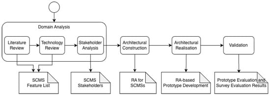
Figure 1.
The research method for our RA design.
4.1. Domain-Oriented Analysis
The first methodological phase focuses on identifying the key functional, quality, and stakeholder-related characteristics of the SCMS domain. We carried out the domain analysis by examining multiple, heterogeneous sources of information. We analysed the scientific publications to identify conceptual models, optimisation strategies, and quality concerns discussed in the research community. Additionally, we analysed the commercial SCMS solutions to identify commonly supported capabilities, any aspects that can be configured for different contexts, and any operational limitations.
We analysed each source independently to reduce bias during feature identification. The extracted concepts were systematically abstracted into domain features and stakeholder roles. Recurring concepts across multiple sources were generalised into higher-level features, while conflicting observations were eliminated. Features were finally classified as mandatory or optional based on their relevance across usage scenarios. Through this analysis, the study addresses RQ1 in Section 3 by revealing common and variable SCMS features, and RQ2 by identifying stakeholders and their roles within the domain.
4.2. Architectural Construction
The second phase translates the results of the domain analysis into architectural models. Architectural decisions focused on supporting feature variability, enabling reuse, and separating architectural concerns to manage system complexity. Rather than addressing specific technologies or architectural styles, we defined the RA at a high level, which emphasises component responsibilities, interactions, and dependencies.
To control architectural complexity, we based our RA on multiple viewpoints, each addressing a specific concern such as system boundaries, structural organisation, runtime interactions, or deployment considerations. This phase directly addresses RQ3 in Section 3 by demonstrating how architectural complexity can be managed through explicit separation of concerns and viewpoint-based design.
4.3. Architectural Realisation
To examine to what extent the proposed RA can be effectively applied in practice, a prototype system was developed. The prototype represents an AA derived from our RA. Only a subset of features (i.e., those classified as mandatory) were implemented to demonstrate how the RA can be instantiated under realistic constraints.
During implementation, the selected domain features were implemented using the architectural components defined in the RA. This allowed us to assess whether our RA effectively guided the architectural design decisions and supported the development of a concrete SCMS. This phase addresses RQ4 in Section 3 by demonstrating practical applicability.
4.4. Validation Approach
To validate the usability and practical applicability of our RA, we conducted two complementary strategies: architectural realisation and stakeholder-oriented evaluation. Architectural realisation evaluates whether our RA can effectively guide the design and implementation of a concrete AA. This evaluation focuses on the clarity of architectural viewpoints, traceability between domain features and architectural elements, and the feasibility of applying the RA in a real development setting. Stakeholder-oriented evaluation collects feedback from developers, charging station managers, and EV drivers to evaluate the usability of the RA. Therefore, the validation phase directly addresses RQ4 in Section 3 by evaluating the usability and applicability of the proposed RA in realistic contexts.
5. Domain Analysis
Before designing an RA for SCMSs, we focused on analysing the charging management domain for EVs. To this end, we firstly analysed the literature to determine any papers that are concerned with EVs’ charging management. We scanned through Google Scholar and well-known publisher sites (e.g., Elsevier, IEEE, and ACM) and found out 100+ papers that can be categorised as (i) the planning, design, optimisation, and simulation of charging and charging station infrastructures [64,65,66], (ii) integration with electrical grids [67,68,69], (iii) energy management [70,71], (iv) the enabling technologies for EV charging management [16,19,72], (v) the analysis of driver behaviours [73,74,75], and (vi) future directions [20,76,77]. We examined each paper thoroughly and determined any concerns that are discussed in those papers and can be considered as a functionality or quality requirement for an SCMS. We also identified any stakeholders who have been involved in the analysis, design, implementation, and operation phases of SCMSs. Besides our literature analysis, we conducted a comprehensive analysis of the existing technologies for EV charging management. To this end, we searched on Google for any existing technologies via such keywords as “smart EV charging management”, “EV charging management applications”, “smart systems for EV charging”, “mobile apps for EV charging”, “AI-based EV management”, “car charging app”, “EV management app”, etc. Thus, we managed to find the details of more than 100 different SCMSs over their websites. Having gone through their websites, we examined the technology features, stakeholder descriptions, different types of solutions, pricing packages, and any other resources (e.g., white papers, case studies, videos, user manuals, demos, and blogs).
Our analysis of the literature and existing technologies aids in collecting a large set of features that can be supported by SCMSs, their decompositions into sub-features, and their status (i.e., mandatory and optional). Moreover, the analysis results aid us in determining the potential stakeholders involved in the SCMS product lifecycle.
To validate the identified list of features and stakeholders, we conducted a survey among 69 EV drivers. We reached the participants via our personal contacts, social media (e.g., LinkedIn), relevant forums, and contact information of the existing technologies. Our survey helped us understand (i) to what extent EV drivers use the existing SCMSs, (ii) drivers’ main motivations for using SCMSs, (iii) the features that are more important for EV drivers, (iv) the top-used commercial tools for EV charging management, and lastly, (v) drivers’ challenges on using SCMSs. Using our survey results (the details of the survey for validating the SCMS features can be reached via the following link: https://zenodo.org/records/15335438, accessed on 1 November 2025), we were able to revise our feature set. Indeed, we added new features that are essential for EV drivers but not included in our initial feature set, removed any features from our initial feature set that are not so important for EV drivers, and adjusted the status of the features with regard to EV drivers’ level of interest (i.e., mandatory or optional). Lastly, note that this survey was conducted solely to perform feature refinement and was not part of our RA evaluation discussed in Section 7.
Having determined the features for SCMSs, we intended to identify the stakeholders involved in the operations of those features. We benefited from our research materials (i.e., the collected papers, similar technologies, and survey results) and identified (i) any types of users who use SCMSs for some purposes, (ii) any stakeholders who contribute to the SCMS development lifecycle, (iii) any data sources that share data with SCMSs, and (iv) any external systems that can either provide data to SCMSs or require data from SCMSs. Table 1 shows the stakeholders that we determined from our domain analysis. The driver here is the main stakeholder who performs tasks such as locating the nearest charging station, making an online reservation and payment, and navigating to the station. The administrator is responsible for maintaining an SCMS, implementing changes and tracking, and monitoring SCMS operations to detect and correct any issues. The charging station manager tracks and monitors charging stations in real time, detects any issues, and plans for maintenance to optimise charging stations. The energy provider monitors the electricity demands from charging stations and manages the electricity usage by means of, e.g., load balancing between stations, dynamic pricing, and electrical grid optimisation. The property manager monitors the performance of charging stations, plans for operational maintenance, and demands extra stations depending on the usage frequencies. The EV manufacturer focuses on the integration with in-car infotainment systems and using data from SCMSs for monitoring battery health and energy usage. The developer is responsible for analysing, designing, and implementing SCMSs in accordance with the system requirements. The data analyst manages data analytics processes including structuring of the data to be collected, and selecting optimum (i) data sources and (ii) data transmission techniques and technologies. Data sources such as sensors and cameras provide any relevant data with an SCMS such as data about the occupancies of charging stations. An external system represents any technology or ecosystem that is integrated with an SCMS so as to meet any functional or quality requirements such as payment processor and in-vehicle infotainment systems. Figure 2 illustrates one of the key interaction flows between those stakeholders, showing their role and responsibilities in handling SCMS functionalities.

Table 1.
The stakeholders involved in SCMSs and their goals.
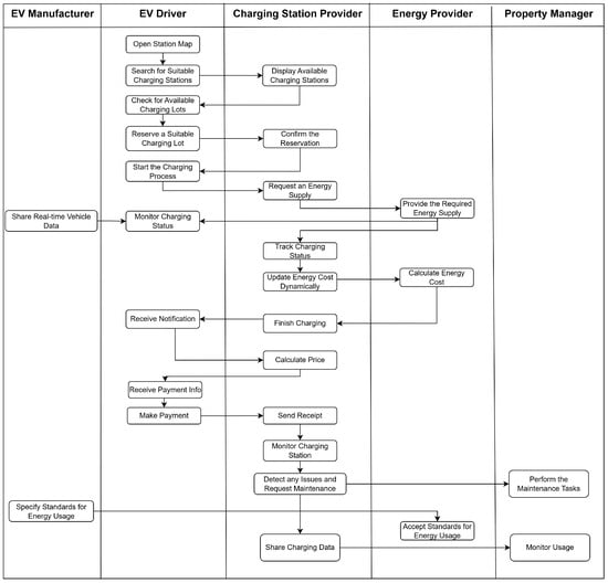
Figure 2.
The interaction diagram for the SCMS stakeholders.
We used the Feature-Oriented Domain Analysis (FODA) method so as to analyse and model the SCMS features [78]. Thus, we came up with a feature model that consists of the features for the SCMS product family where a feature represents either an SCMS functionality or a quality characteristic. Each feature has a status which is either optional or mandatory. An optional feature does not have to be possessed by each SCMS product, while a mandatory feature must always be possessed by every SCMS product. A feature model can be specified in a hierarchical way (i.e., tree-like structure), and thus, each feature can be specified in terms of sub-features that can be either optional or mandatory. Additionally, for any feature, its sub-features can be related with an “OR” relationship, which indicates that the feature must be represented with at least one of the related sub-features. Figure 3 gives the feature model for the SCMS product family. The charging monitoring feature supports the real-time monitoring of EV charging processes for tracking the charging performance and managing the charging cost. The charging monitoring feature consists of a set of mandatory sub-features which are (i) the real-time monitoring, (ii) initiating and controlling charging sessions remotely, (iii) the automated delivery of notifications and alerts, (iv) managing records of session histories, and (v) tracking energy usage. Notifications and alerts is the only optional feature here. The charging station management feature optimises EV charging operations for different stakeholders such as EV drivers and charging station managers. The charging station management feature consists of several sub-features: (i) diagnostics for the quick detection of problems (e.g., connectivity issues), (ii) error reporting for notifying users about any errors occurring, (iii) maintenance for scheduling any repair operations, (iv) loyalty (or rewards) for offering discounts to frequent members, (v) charging statements for giving detailed information about the charging sessions, (vi) monitoring and control for the real-time management of charging sessions, (vii) localisation for locating the nearest charging stations, (viii) energy management for the efficient use of energy, (ix) an environmental impact summary for reporting the environmental benefits, and (x) load balancing for distributing the electrical power among multiple chargers. Note that while the charging statement and monitoring and control are the mandatory sub-features, the rest of the sub-features are optional. The EV driver profile feature supports drivers to improve their EV driving and charging experiences. The EV driver profile includes a set of sub-features which are (i) account management (e.g., managing personal information), (ii) preferences and notifications (e.g., notifications about charging status), (iii) driver statistics (e.g., charging history), (iv) vehicle management for the users to improve their EV charging processes, and (v) driver and vehicle analytics for receiving useful recommendations upon the analysis of charging data. The mandatory sub-features for the EV driver profile are driver statistics and account management. The reservation feature supports the online pre-booking for any available charging lots. The reservation feature consists of several sub-features: (i) scheduled charging, (ii) charging preferences, (iii) cancellation, (iv) priority access, and (v) real-time availability. The scheduled charging and cancellation sub-features are mandatory. The navigation feature supports EV drivers who need to be guided to the charging lots by the quickest way possible. The navigation feature has the following sub-features: (i) route planning and viewer, (ii) route recommendation, (iii) route optimisation, (iv) dynamic routing, and (v) offline navigation. Route planning and viewer is the only mandatory sub-feature for navigation. The map feature enables searching for charging stations and interacting with them. The map feature includes the following sub-features: (i) station filtering, (ii) station availability, (iii) a station locator, (iv) an offline map, (v) nearby amenities, (vi) station details, and (vii) a station review. Here, the station availability, station locator, and station details sub-features are mandatory. The payment feature supports the payment activities for EV charging services and consists of a set of sub-features: (i) multi-platform payment (e.g., in-car, mobile app, and web), (ii) dynamic pricing based on different factors such as the period of day, electricity rates, and location, (iii) payment options (e.g., credit card, digital wallets, and monthly payment plans), (iv) auto-pay for automated payment, (v) billing, (vi) discount, and (vii) refund. While the dynamic pricing and discount sub-features are optional, the rest of the sub-features for payment are mandatory. The administration feature supports the effective operations of administrative tasks such as the real-time monitoring of charging performance, generating useful reports, managing users and many other aspects (e.g., fleet, tariffs, and pricing), and system maintenance. Thus, the sub-features here consist of (i) monitoring, (ii) reporting, (iii) maintenance and updates, (iv) notifications and alerts, (v) fleet management, (vi) charging station registration and configuration, (vii) billing and pricing management, (viii) user management, (ix) user support, and (x) tariff management. The monitoring and user management sub-features are mandatory. The data management feature supports the collection, storage, processing, analysis, and presentation of data in the SCMS product lifecycle. The data management feature has an OR relationship with a set of sub-features, which asserts that at least one sub-feature must always be satisfied by any SCMSs. The sub-features here are (i) data acquisition, (ii) data storage, (iii) data processing, (iv) decision making, and (v) data visualisation. The security feature supports the protection of any data that are possessed by an SCMS and users against any threats. The security feature has an OR relationship with a set of sub-features which are (i) availability (i.e., the services being always available), (ii) integrity (i.e., ensuring the correctness, completeness, and consistency of data), and lastly, (iii) confidentiality (i.e., ensuring the data are not accessed by unauthorised users). The smart home integration feature supports the integration with smart home technologies to enable interactions between home devices and an SCMS. The smart home integration feature has an OR relationship with a set of sub-features which are (i) home ecosystem integration (e.g., smart devices, software applications, and smart platforms), (ii) monitoring and control of the charging status via smart home technologies, (iii) energy management for minimising energy costs with the use of home energy sources, and (iv) reporting for understanding how much the energy cost is reduced via the use of home energy. Lastly, the energy management feature supports the optimised use of energy sources for EV charging. The energy management feature has an OR relationship with a set of sub-features which are (i) load balancing, (ii) optimisation, (iii) renewable energy integration, (iv) monitoring and control, (v) building ecosystem integration, and (vi) tariff management. Note that the energy management sub-feature of the charging station management feature is concerned with the energy usage at the station level, while the energy management feature is concerned with managing energy sources at a system level.
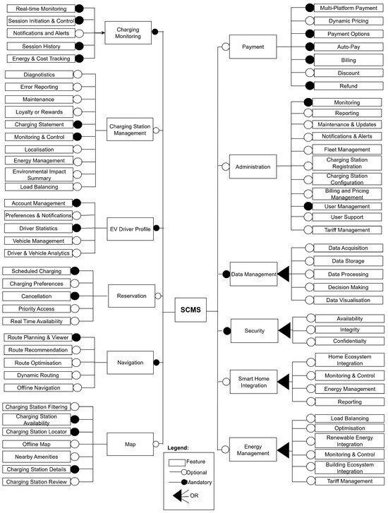
Figure 3.
The feature model for SCMSs.
6. Reference Architecture (RA) Design for SCMSs
To design our RA for SCMSs, we considered the architecture viewpoints modelling approach so as to manage the complexity of software architectures in terms of separate viewpoints, each of which addresses a distinct concern for the architecture-centric development of software systems [79]. Any viewpoint essentially consists of (i) a clear name, (ii) a concern to be addressed, and (iii) a notation set for specifying abstract models with regard to the corresponding concern(s).
Our RA design for SCMSs is based on the architecture viewpoints that have been proposed by Clements et al.’s seminal work on software architecture viewpoints [80]. Clements et al. focused on the needs of stakeholders from an architectural documentation and addressed what an architect actually needs in their processes of architecture documentation. According to Clements et al., an architecture document for any system to be developed must consider (i) the structuring of the software development units, (ii) the structuring of the executing components, and (iii) the physical structuring and mapping of the executing components to the physical components. Therefore, we proposed four different viewpoints, each of which addresses a specific concern on the development of SCMSs. These viewpoints are the context, module, component and connector, and allocation viewpoints. Each viewpoint promotes the decomposition of an SCMS from a particular perspective and a set of reusable elements that can be used for specifying the architecture of any SCMSs under certain rules and constraints.
6.1. Context Viewpoint
Figure 4 depicts the context viewpoint for SCMSs, which describes the stakeholders, and their roles and responsibilities for the development and operation of SCMSs. A stakeholder can be either mandatory or optional. The mandatory stakeholders are essential and their existence does not change from one SCMS to another. The optional stakeholders do not have to exist for every SCMS and their existence depends on the specific requirements of SCMSs. The EV driver, administrator, charging station manager, and developer are the mandatory stakeholders, while the rest of the stakeholders given in Figure 4 are optional.
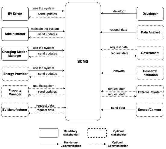
Figure 4.
The context viewpoint model for SCMSs.
As also depicted in Figure 4, stakeholders’ interactions with SCMSs can either be optional or mandatory and each stakeholder can be involved in one-way or two-way interactions. For instance, stakeholders such as the EV driver, administrator, charging station manager, and energy provider are involved in two-way interactions with SCMSs. While those stakeholders always interact with an SCMS, an SCMS may send any updates back to the stakeholders optionally.
6.2. Module Viewpoint
Figure 5 depicts the module viewpoint for SCMSs, which describes the software implementation units that can be used for developing an SCMS. In the module viewpoint definition, we considered a distinct software implementation unit for each feature given in Figure 3 and each implementation unit consists of a distinct software module for implementing a specific sub-feature of the associated feature. Note that a software module can be either a software class, a procedure, interface, namespace, or software library.
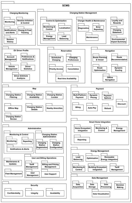
Figure 5.
The module viewpoint model for SCMSs.
The charging monitoring unit represents the functionalities for the real-time monitoring of charging processes, which are used by many stakeholders such as EV drivers, charging station managers, administrators, energy providers, and property managers. The charging monitoring unit consists of five software modules: (i) monitoring, (ii) session initiation and control, (iii) notifications and alerts, (iv) session history, and (v) energy and cost tracking. The charging station management unit represents the functionalities that are used by many stakeholders including EV drivers, charging station managers, administrators, energy providers, and property managers for the optimisation of EV charging operations. The charging station management unit consists of five software modules: (i) control and optimisation, (ii) charger health and maintenance, (iii) loyalty and rewards, (iv) charging statement, and (v) environmental impact summary. Control and optimisation is further decomposed into four sub-modules, which are (i) monitoring and control, (ii) localisation, (iii) energy management, and (iv) load balancing. Likewise, charger health and maintenance is decomposed as (i) diagnostics, (ii) error reporting, and (iii) maintenance. The EV driver profile unit represents the functionalities that are used by EV drivers for managing their charging processes. The EV driver profile unit consists of five modules which are (i) account management, (ii) preferences and notifications, (iii) vehicle management, (iv) driver statistics, and (v) driver and vehicle analytics. The reservation unit represents the functionalities that are used by drivers and charging station managers for managing the reservation processes of charging lots. The reservation unit consists of five modules which are (i) scheduled charging, (ii) charging preferences, (iii) priority access, (iv) cancellation, and (v) real-time availability. The navigation unit represents the functionalities that are used by drivers to guide them to the reserved charging lots. The navigation unit consists of five modules which are (i) route planning and viewer, (ii) route recommendation, (iii) route optimisation, (iv) dynamic routing, and (v) offline navigation. The map unit represents the functionalities that are used by drivers and charging station managers to utilise information from the street maps of charging stations. The map unit consists of seven modules which are (i) charging station filtering, (ii) charging station availability, (iii) charging station locator, (iv) offline map, (v) charging station details, (vi) nearby amenities, and (vii) charging station review. The payment unit represents the functionalities that are used by drivers, charging station managers, and administrators for managing the payment processes. The payment unit consists of seven modules which are (i) multi-platform payment, (ii) dynamic pricing, (iii) payment options, (iv) billing, (v) auto-pay, (vi) refund, and (vii) discount. The administration unit represents the functionalities that are used by the administrators for performing the administrative tasks about the operations of SCMSs. The administration unit consists of five modules which are (i) monitoring and control, (ii) charging station administration, (iii) maintenance and updates, (iv) fleet management, and (v) user and billing operations. Monitoring and control is decomposed into sub-modules which are (i) monitoring, (ii) reporting, and (iii) notifications and alerts. Charging station management is decomposed into the charging station registration and charging station configuration sub-modules. Likewise, the user and billing operations module is further decomposed into the (i) tariff management, (ii) billing and pricing management, (iii) user management, and (iv) user support. The smart home integration unit represents the functionalities that are used by drivers for the integration with smart home devices. The smart home integration unit consists of four different modules which are (i) home ecosystem integration, (ii) monitoring and control, (iii) energy management, and (iv) reporting. The energy management unit represents the functionalities that are used by energy providers for the optimised use of energy sources for EV charging. The energy management unit consists of six different modules which are (i) load balancing, (ii) optimisation, (iii) renewable energy integration, (iv) monitoring and control, (v) building ecosystem integration, and (vi) tariff management. The security unit represents any services for securing the data that are collected, stored, analysed, and transmitted for diverse operations of SCMSs. The security unit consists of three modules which are (i) confidentiality, (ii) integrity, and (iii) availability. The data management unit is responsible for the data analytics operations which include collecting data from data sources and storing them, and processing and analysing data for making smart decisions that can be used by other software units and their modules. The data management unit consists of five modules which are (i) data acquisition, (ii) data storage, (iii) data processing, (iv) decision making, and (v) data visualisation.
6.3. Component and Connector Viewpoint
From this viewpoint, we defined the components and connectors that can be re-used for specifying the runtime structure of SCMSs. Components represent the main computation units, each of which has a specific responsibility that contributes to the main goal of SCMSs. Connectors represent the communication and coordination mechanisms among the components that can either be simple communication links or complex protocols of interaction. To organise the components and connectors, we applied the layered architecture style which promotes the related components to be grouped into distinct layers that can communicate under strict interaction rules [81]. In the layered architecture style, each layer represents a set of components that address the same concern (e.g., user-interface presentation, security, business logic, and data management). Layers are ideally organised in a hierarchical manner (i.e., top-down). Components within any layer may provide services to the components within other layers that are located at higher levels in the hierarchy and may request services of the components within the lower-level layers.
To determine the layers and components for the SCMS product family, we utilised our module viewpoint that is discussed in Section 6.2. For our component and connector viewpoint, we considered a distinct component that can operate each software unit in the module viewpoint and further identified any missing components that are not represented with any of the software units (e.g., user interface components). Figure 6 depicts the component and connector viewpoint for SCMSs. The top layer here is the presentation layer which groups together the components that handle user interactions and present any useful information to users. The components of the presentation layer each represent a specific user interface type (i.e., web, mobile, and desktop) and users perform any functionalities by interacting with the associated user interfaces depending on their access rights. When users interact with SCMSs, the corresponding component(s) of the presentation layer request the appropriate services of the appropriate component(s) from the business logic layer. The business logic layer includes a distinct component for each main software unit whose goal is to perform the corresponding computations. The business logic components are (i) payment, (ii) map, (iii) reservation, (iv) EV driver profile, (v) administration, (vi) navigation, (vii) charging monitoring, (viii) energy management, (ix) smart home integration, and (x) charging station management. Upon receiving requests from the presentation layer, the business logic components perform their computations which may require some data to be accessed, changed, or created. Therefore, the business logic components request services from the data management layer components (i.e., the bottom layer) which are responsible for acquiring data from data sources, storing those data, processing and analysing data, and visualising the data analysis results. Lastly, the security layer operates the security software unit from the module viewpoint definition and provides services to all other layers for secure data access and communications. The security layer includes a distinct component for each software module of the security software unit and each security component addresses a particular aspect of data security (i.e., confidentiality, integrity, and availability).
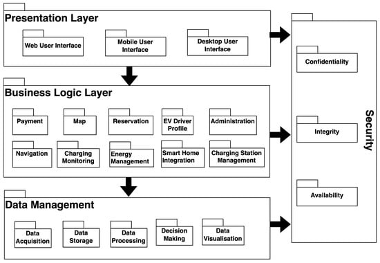
Figure 6.
The component and connector viewpoint model for SCMSs.
6.4. Allocation Viewpoint
The allocation viewpoint is concerned with mapping software components to physical and virtual devices, such as servers, to meet the system-level goals (e.g., system performance, resource consumption, and reliability).
In Figure 7, the allocation viewpoint for the SCMS product family is depicted. In the allocation viewpoint, we applied the distributed client–server architecture style [82], which promotes the physical organisation of SCMSs into client and server devices that interact with each other in a distributed manner. We considered four types of components for the allocation viewpoint, which are (i) client, (ii) server, (iii) data source, and (iv) external system.
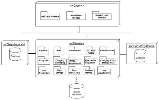
Figure 7.
The allocation viewpoint model for SCMSs.
A client component here executes a software component from the presentation layer of the component and connector viewpoint discussed in Section 6.3. A presentation layer component can be a web, mobile, or desktop user interface. Client components can run on any user devices such as smartphones, laptops, in-car systems, and kiosk machines.
A server component here executes a set of components from the business logic layer of the component and connector viewpoint discussed in Section 6.3. These components can be charging monitoring, navigation, payment, charging station management, energy management, etc. Additionally, the server component is further supposed to execute all software components of the data management layer.
Server components can operate on a centralised physical device or cloud-based virtual server. Stakeholders (e.g., developers and charging station managers) can choose the best deployment option depending on their quality expectations, e.g., performance, scalability, security, and project budgets.
Besides clients and servers, any data sources and external systems can be involved in the physical architectures of SCMSs. A data source is an external component which can provide data to a server so that the business logic components (e.g., navigation, charging station management, and charging monitoring) which are allocated in a server can perform their functionalities. Data sources can be (i) sensors and cameras, (ii) databases, or (iii) APIs (e.g., the APIs for the charging stations, maps, weather services, and energy providers).
In the allocation viewpoint, the final component type is the external system which can introduce new features for SCMSs such as load balancer, smart home integration system, charging station management system, and energy management system.
While the component and connector viewpoint includes a security layer in Figure 6, we did not include the security layer components in any of the devices. It should be noted that we consider security a cross-cutting concern for the allocation viewpoint and therefore believe that security components should be addressed in terms of a set of behavioural rules, constraints, and interaction protocols that need to be satisfied by the software and physical components.
The components of the allocation viewpoint depicted in Figure 7 can interact with each other under certain rules and protocols. Clients send requests to servers and servers send back responses. The communication protocols between clients and servers can be HTTP or HTTPs. Servers can interact with their databases to store and access any data under certain communication protocols (e.g., HTTPs and TCP/IP). Servers can interact with external systems and data sources so as to request some data under such protocols as HTTPs.
7. Evaluation
To validate our RA design for SCMSs comprehensively, we performed two types of evaluations which are prototyping and surveying. In our prototype-based evaluation, we designed and implemented an SCMS case study in accordance with our RA and conducted interviews among the developers who developed the SCMS prototype to measure the applicability of our RA design in a real-world scenario. In our survey-based evaluation, we conducted a survey among stakeholders, including charging station managers, developers, and EV drivers, to measure the usability of our RA.
7.1. Prototype-Based Evaluation
7.1.1. Case Study
In our prototype development, we considered the EV charging problems in Istanbul, Türkiye, where the number of EV charging stations have been constantly increasing. As discussed in Section 5, EV drivers in Istanbul suffer from several issues. To better understand the problem, we conducted a survey among 69 EV drivers which led to interesting findings about EV drivers’ motivations and challenges (the details of the survey can be reached via the following link: https://zenodo.org/records/15335438, accessed on 1 November 2025). EV drivers’ main motivations include (i) determining the nearest charging stations and the real-time monitoring of their availabilities, (ii) comparing the price information of different stations, (iii) trip planning and route optimisation, and (iv) remote monitoring of charging progress. EV drivers’ main challenges include (i) technical issues (e.g., crashing applications, poor connectivity, compatibility issues, and software bugs), (ii) poor user interface/design, (iii) slow loading times, (iv) lack of integration with external systems (e.g., payment processors), and (v) incorrect, inaccurate, and outdated information (e.g., inaccurate station information, incorrect battery health information, and wrong charging speed).
Upon analysing the survey results, we further conducted one-to-one interviews with EV drivers who have been easily accessible. Thus, we identified the functional and quality requirements for the desired SCMS to be used by EV drivers in Istanbul. We prioritised the requirements depending on our context and defined our goal of developing an SCMS that enables EV drivers to (i) locate the charging stations that best suit their needs, (ii) make remote reservations, and (iii) receive smart recommendations for post-parking processes. Moreover, the desired SCMS can be used by charging station managers who can design their charging stations via a user-friendly editor and monitor the usage of their charging stations.
7.1.2. Developing an SCMS Prototype
We aimed to analyse, design, and implement an SCMS product for the use case discussed in Section 7.1.1. To this end, we worked together with the members of our software engineering research group (SERG website: serg.yeditepe.edu.tr). We selected six developers who have been among the top-ranked senior undergraduate students and worked as part-time developers in well-known software development companies. Initially, we conducted a meeting with the developers (in the rest of the paper, we refer to the students who were involved in the SCMS prototype development as developers) and discussed our RA design. In this meeting, we introduced the use of our RA for SCMSs and discussed the feature model along with viewpoint definitions. Then, we answered the developers’ questions and ensured that the students clearly understood the RA design. After ensuring that the developers were clear about the RA viewpoints, we conducted another meeting to inform the developers about the SCMS requirements that we have collected as discussed in Section 7.1.1. In this meeting, we discussed the requirements on a whiteboard thoroughly and answered the developers’ questions. We concluded our meeting upon ensuring that the developers fully understood the requirements.
After the meetings, the developers were given 10 weeks to develop an SCMS prototype by using the RA design. Initially, the developers focused on our RA’s feature model and identified the features that are essential and those that can be omitted in their prototype version due to the limited amount of time and other resources (e.g., hardware and technical expertise). Figure 8 depicts the features and their sub-features that the developers decided to consider for their prototype.
Figure 8.
The feature model for the SCMS prototype.
Upon specifying the feature model, the developers proceeded with the AA specification of their SCMS prototype by re-using our RA design. That is, the developers re-used the RA viewpoint definition models and specified their specific view models that meet the needs of their case study. Firstly, the developers focused on establishing the boundary of their prototype in terms of the stakeholders and their roles and responsibilities. To this end, the developers used RA’s context viewpoint and specified the context view model in Figure 9 which depicts six main stakeholders who are involved in the development and operating phases of the SCMS prototype. Those are the EV driver, administrator, charging station manager, developer, research institution, and external system (i.e., Google Maps). After determining the context, the developers used our RA’s module viewpoint to determine the software units to be developed for the SCMS prototype. The developers specified the module view model that is depicted in Figure 10 and decided on the software units and their modules for the SCMS prototype. Next, the developers focused on organising the software development units into the executing parts of their SCMS. To this end, the developers used RA’s component and connector viewpoint and specified the view model depicted in Figure 11. Note that the developers re-used a subset of the software development units defined in RA’s module viewpoint, and therefore, a subset of the components in RA’s component and connector viewpoint. Lastly, the developers used our RA’s allocation viewpoint to make decisions when allocating the executing software components into the physical components and specified the allocation view model depicted in Figure 12. Thus, in the SCMS prototype, each client device includes the mobile user interface component and the server includes all the business logic components (e.g., map, navigation, reservation, EV profile, etc.) and the data management components. Moreover, the server device communicates with an external system that provides the map and navigation data via the Google Maps API.
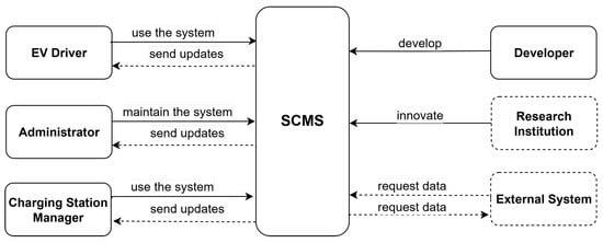
Figure 9.
The context view model for the SCMS prototype.
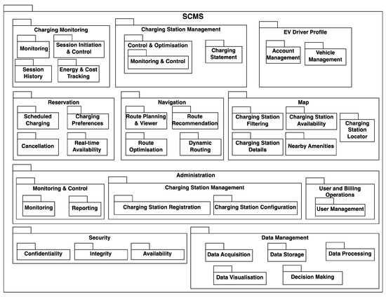
Figure 10.
The module view model for the SCMS prototype.
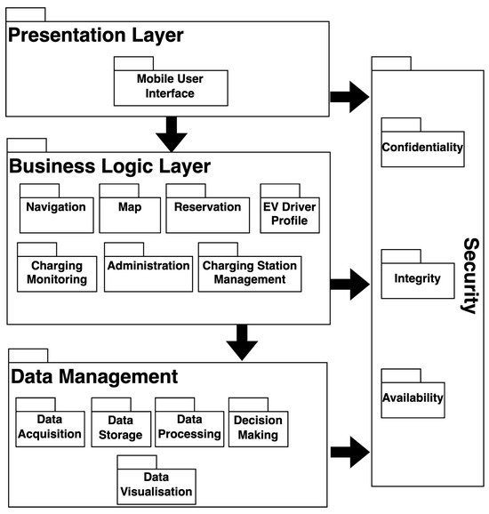
Figure 11.
The component and connector view model for the SCMS prototype.
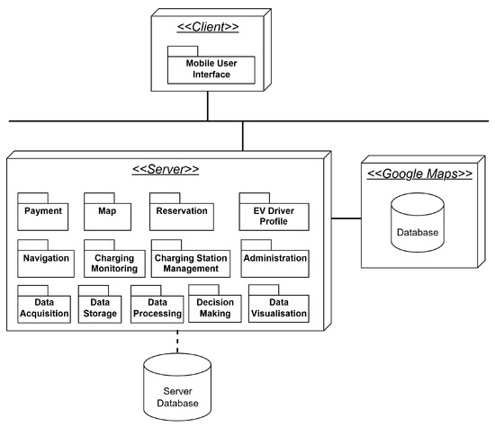
Figure 12.
The allocation view model for the SCMS prototype.
The developers documented their RA-based, multiple-viewpoints SCMS architecture, which is discussed above, over 3 weeks. Having finalised the architecture, the developers spent approximately one week selecting appropriate technologies to be used including the programming technologies, software libraries, database systems, frontend frameworks, and communication protocols. Then, the developers implemented their SCMS product over six weeks by strictly following the architectural decisions. Figure 13 depicts the key user interfaces from the SCMS product that the developers implemented successfully.
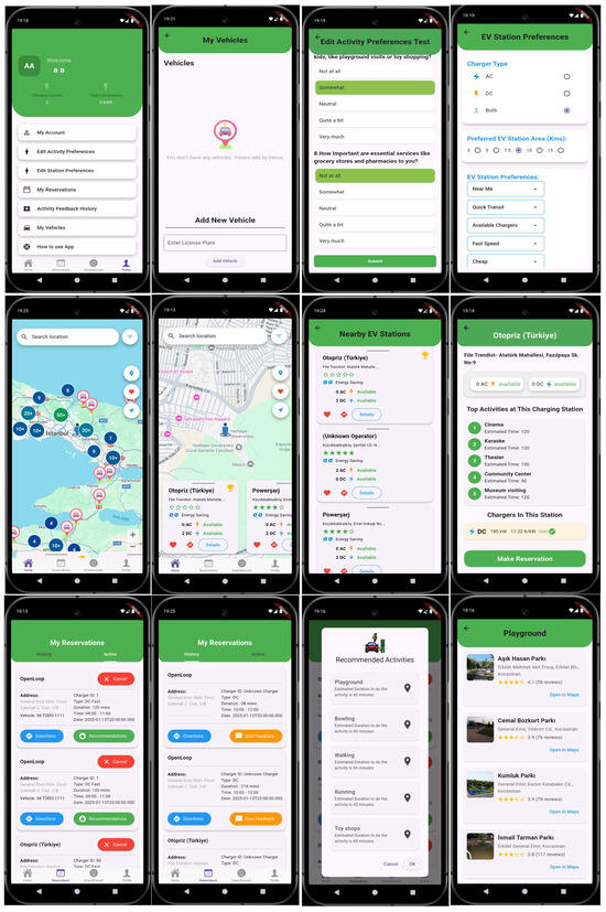
Figure 13.
The user interfaces of the SCMS prototype.
7.1.3. Measuring Our RA’s Applicability in Real-World Scenarios
After the developers implemented their SCMS product, we conducted interviews with the developers to understand their perspectives on the applicability of our RA in real-world scenarios.
To design the interview questions, we utilised our past experiences [83,84,85] and examined several related surveys. We also reviewed guidelines on survey design and interviewing techniques [86,87]. Thus, we ended up with four key questions for evaluating the RA applicability. We further performed a pilot study with key stakeholders including EV drivers, developers, researchers, and surveying experts and improved our questions in accordance with their feedback.
To conduct our interview, we organised a two-hour meeting with the developers. We recorded the developers’ responses for each question. After an initial interview, we analysed the responses given for each question to come up with a common perspective. Then, we conducted another interview with the developers to ensure that the identified common perspective for each question was complete, correct, and consistent for each developer.
In our first question, we sought to learn to what extent our RA design was easy to learn and use. According to the developers, our RA design was easy to understand given its cleanly separated viewpoints, each of which has a precisely defined role and responsibilities. The developers also found the notation set of each RA viewpoint easy to learn and use, which essentially derives from the well-known, de-facto UML modelling language [88]. Moreover, the traceability between the RA elements and viewpoints (e.g., moving from the feature model to the module viewpoint model and the component and connector model to the allocation model) was found to be straightforward and easy to follow.
In our second question, we focused on to what extent our RA design was capable of guiding the developers in their requirements gathering and the rest of the SCMS development processes. The developers stated that the feature model for our RA design was sufficient for them to identify all necessary features and sub-features for their specific SCMS. Indeed, the developers did not find it necessary to introduce any new features apart from those given in our feature model. The developers agreed that our RA design is certainly a valuable guide in making early design decisions for any SCMSs, which promotes the identification of stakeholders, grouping software implementation units, organising system components into layers, and mapping components with physical units. While security is the only quality property considered in our RA design, the developers were all aware that other crucial quality properties (e.g., performance, fault tolerance, and reliability) can be tackled with a detailed design that follows the high-level design using our RA.
In our third question, we focused on understanding to what extent our RA design aids developers in understanding the principles of RA design and the enabling techniques (e.g., model-based engineering and product-line engineering). According to the developers, our RA design let them realise the importance of developing a product family rather than a single product which can significantly contribute to re-usability and maintainability while reducing costs and increasing quality. Moreover, our RA design made the developers experiment with many critical techniques including architecture-centric software development, requirements traceability, code generation from architectural models, and optimal system partitioning.
In our fourth question, we intended to understand the developers’ experiences when implementing an SCMS product using our RA design. The developers were able to implement their SCMS product in a way that satisfies their RA viewpoint models. The developers indicated that adopting our RA design significantly improved their development performance as it highly reduced the effort needed for analysing the SCMS features, establishing system boundaries, determining the mappings between logical and physical components, and maintaining the system when errors were detected. Concerning the challenges, the developers faced some issues that are not directly addressed in our RA design. For instance, structuring components in each layer further required the adoption of a microservices architectural style, while the component interactions required an event-driven style both of which were not included in our RA. Moreover, the developers addressed the need for manual transformation of models into code as no code generator was provided for the automated generation of skeleton code from the viewpoint models.
7.2. Survey-Based Evaluation
As part of the evaluation phase, we conducted a survey to assess the clarity, usability, and practical relevance of our RA. It should be noted that this survey is distinct from the earlier survey reported in the domain analysis discussion in Section 5, which focused on validating SCMS features from an EV driver perspective. The evaluation survey here targets a broader set of stakeholders and specifically addresses how well our RA supports architectural understanding and early design decisions.
7.2.1. Survey Design and Execution
To design our survey, we used our past surveying experiences in diverse fields and problem domains [83,89,90] and well-known survey guidelines [86,87].
Our survey consists of 22 different questions which are depicted in Table 2. The survey questions were organised into distinct categories based on our RA viewpoints. Upon learning the participants’ profile information (i.e., their role in relation to any SCMSs), we asked questions to learn the participants’ opinions on the feature model that our RA is based on. Following that, we asked questions to learn the participants’ opinions about each RA viewpoint definition. Lastly, we concluded with a set of general questions. For simplicity purposes, we designed most of the questions with a single-answer choice. We used the Likert scale for the single-answer questions for precision. That is, rather than providing “Yes” and “No” answer types, we provide more precise answer lists such as “Not at all”, “Somewhat”, “Moderately”, “Mostly”, and “Completely”. A few of the questions require free-text answers which force the participants to type their answers freely.
We conducted our survey online via Google form in May–August 2025. Our survey targeted individuals with technical expertise in any relevant fields including EV management systems, energy management, and charging infrastructures. To spread the survey, we initially used our personal contacts from past relevant projects. Furthermore, we shared our survey link via social media, such as LinkedIn, and sent the survey link to the tool vendors who offer smart transportation products. Thus, we reached 33 participants from diverse roles (the survey questions and raw data for the survey responses can be accessed via the following link: https://zenodo.org/records/16016810, accessed on 1 November 2025).
7.2.2. Analysis of Survey Results
In this section, we discuss the results of our survey in terms of the question categories: profile question, feature model questions, and the RA viewpoint-related questions. While the participants provided valuable feedback about RA’s feature model and viewpoint definitions and suggested some changes (e.g., adding new features, combining existing software units, adding new stakeholders, etc.), we did not perform those changes in our RA. The main goal of our survey is to evaluate our RA design rather than revising it. Therefore, any suggested improvements have been left as future work.
Concerning Q1, most of the participants were EV drivers (54%) and developers (29%). The rest of the participants include charging station managers, energy systems managers, researchers, and system administrators. Note that our survey targeted participants with technical expertise who can understand the reference architecture concepts and any related techniques and technologies.
Table 2.
The survey questions for evaluating our RA.
Table 2.
The survey questions for evaluating our RA.
| Category | Questions | Single Answ. | Free Text |
|---|---|---|---|
| Profile | 1- What is your primary role in relation to SCMS? | X | |
| Feature Model | 2- Does the feature model cover all necessary features for an effective SCMS? | X | |
| 3- Are there any missing features in the feature model that you think should be included? | X | ||
| 4- Which feature category do you think is the most underrepresented in the current feature model? | X | ||
| 5- Does the feature model appropriately distinguish between mandatory, optional, and OR features? | X | ||
| 6- Are there any features in the model that seem unnecessary or overly complex for a practical SCMS implementation? | X | ||
| Context | 7- Does the context viewpoint clearly define the boundaries of an SCMS? | X | |
| 8- Are the interactions between an SCMS and external entities adequately represented? | X | ||
| 9- Does the context viewpoint effectively capture the roles and responsibilities of all relevant stakeholders? | X | ||
| 10- Are there any stakeholders missing from the context viewpoint that should be included? | X | ||
| Module | 11- Are the modules logically organized and comprehensive for an SCMS ? | X | |
| 12- Does the module viewpoint adequately address the functional requirements of an SCMS? | X | ||
| 13- Are there any modules that seem redundant or could be combined for better clarity? | X | ||
| 14- Is the granularity of the modules appropriate (e.g., are they too broad or too specific)? | X | ||
| C&C | 15- Are the components clearly defined and appropriate for an SCMS? | X | |
| 16- Do the connectors between components effectively support the system’s runtime behaviour? | X | ||
| Allocation | 17- Does the allocation viewpoint clearly map software components to hardware resources? | X | |
| 18- Is the allocation of components to deployment environments practical and efficient for an SCMS? | X | ||
| General | 19- How clear and understandable is the overall RA design for an SCMS? | X | |
| 20- How usable do you find the RA design for implementing an SCMS? | X | ||
| 21- Does the RA design comprehensively address the needs of an SCMS? | X | ||
| 22- How applicable is the RA design to real-world SCMS deployment scenarios? | X |
Concerning Q2–Q6, most of the participants believe that our feature model covers all necessary features. However, a few participants indicated some features and sub-features that can be further added in the feature model. According to the participants, security is the most underrepresented feature in our feature model and can be extended with sub-features related to cybersecurity. The charging monitoring feature can be extended with the manufacturer brand recognition sub-feature which can aid in identifying the manufacturer and facilitate the charging process accordingly. The data management feature can be extended with the predictive maintenance sub-feature for monitoring software/hardware performance and scheduling maintenance. The charging station management can be extended with the user feedback management sub-feature for managing reviews, comments, and issue reports about charging stations. Finally, an emergency feature can be added for managing emergency situations such as power outages and natural disasters. Additionally, the features including administration, payment, and smart home integration were found to be relatively complex.
Concerning Q7–Q10, the majority of the participants found the context viewpoint definitions clear and easy to understand in terms of the boundaries of any SCMSs including different types of stakeholders, their classifications, roles, and responsibilities. The participants were satisfied with the definitions of stakeholder interactions with SCMSs and the clarity of the role specifications. Some participants suggested adding new stakeholders, including maintenance engineer, grid operator, mobile network provider, and third-party charging service provider.
Concerning Q11–Q14, most participants believe that the module viewpoint gives a logical comprehensive organisation of the software units for any SCMSs. The participants further indicated that the software units and their modules sufficiently address the functional features given in the feature model. Moreover, most of the participants were satisfied with the granularity of the development units and their modules. One participant proposed composing navigation and map units into a single unit called “Routing & Location”. Moreover, two participants reported confusion arising from the use of the term Energy Management at different abstraction levels, where it appears both as a system-level feature and as a context-specific sub-feature. It should be noted that this overlap was considered a nomenclature issue rather than a functional deficiency. Lastly, two participants suggested considering monitoring and control as a separate software unit that could cross-cut multiple software units including administration, charging monitoring, and charging station management.
Concerning Q15–Q16, most participants agreed that the component and connector viewpoint definition is appropriate for the run-time organisation of SCMSs. That is, the participants were pleased with the component and connector types proposed and their layered structures.
Concerning Q17–Q18, the majority found the allocation viewpoint definition satisfactory in its guidance for mapping the software components into physical units. The physical devices, the software components that they operate, and their physical connections were found to be clear.
Concerning Q19–Q22, the majority of the participants found our RA design to be clear and understandable so that it can easily be used as guidance by developers when analysing their SCMS requirements, designing high-level solutions, and making decisions for the effective implementation of SCMSs. Moreover, the participants agreed that our RA design is successful in addressing the high-level requirements for developing SCMSs given its manageable structures. Finally, the participants were pleased with the RA’s applicability in real-world deployment scenarios given its support for multiple viewpoint modelling that can easily be re-used and adapted.
8. Discussion
8.1. Summary of Findings
RAs play an important role in supporting software development activities, and especially structuring architectural knowledge within a given problem domain. By addressing common architectural concerns, recurring design decisions, and variability points, RAs enable stakeholders to analyse system requirements and complexity, and plan long-term system evolutions. Despite many RAs being proposed for several industrial domains, the architectural knowledge for SCMSs has remained weak and largely implicit. We believe that this is a significant gap considering the rapid growth of EVs and the increasing need for scalable, interoperable, and adaptable charging management solutions. From a scientific perspective, this paper addresses this gap in the literature by systematically formalising the SCMS domain. This has been achieved through a comprehensive feature model that represents common and variable system capabilities, followed by a set of reusable architectural viewpoints, each of which addresses a distinct architectural concern.
To achieve this scientific objective, we developed our RA in a way that satisfies a set of clearly-defined RQs as discussed in Section 3. Each RQ addresses a distinct aspect of architectural knowledge, ranging from domain commonality and variability to stakeholder roles, architectural structuring, and empirical validation. Accordingly, this section first discusses how the proposed RA addresses each RQ and then elaborates on broader implications, including applicability across contexts, architectural scope, and stakeholder usage.
To meet RQ1, we conducted a comprehensive analysis of the existing literature and technologies to determine any similar approaches and commercial (or free) tools for EV management. Indeed, we have gone through more than 100 papers and 100 different technologies about EV management. This helped us determine several different features for SCMSs, evaluate which of those features are optional and mandatory, and organise the features into sub-features cohesively. We further validated our feature model through a comprehensive survey in which 65 EV drivers participated. By doing so, we were able to eliminate any redundancies, resolve any ambiguities, and add any missing features.
After finalising the feature model, we focussed on RQ2 and worked on identifying the stakeholders involved in the product lifecycle processes for SCMSs. To this end, the results of our analysis efforts improved on the existing literature and available technologies conducted for RQ1. Thus, we determined all potential stakeholders for an SCMS, defined their roles and responsibilities, categorised them as mandatory or optional, and defined their communication details (i.e., their status and one-way or two-way communication).
To address RQ3, we proposed the division of our RA design into four viewpoints, which are context, module, component and connector, and physical. By doing so, the complexity of SCMS architectures can be managed by separating different concerns that each have, different scopes, goals, and architectural elements, represented with a distinct notation set. The context viewpoint aids in modelling the mandatory and optional stakeholders for an SCMS, and their roles and relationships in the SCMS. The module viewpoint aids in modelling the software development units that need to be implemented for an SCMS and the modules that compose the units. The component and connector viewpoint aids in modelling the executing parts of the system (i.e., components) and their interaction details (i.e., connectors). Lastly, the allocation viewpoint aids in modelling the physical components that compose the physical structure of an SCMS and the software components that each physical component encapsulates.
To address RQ4, we validated our RA design for SCMSs by means of prototyping and surveying. Our prototype-based evaluation focused on a case study that is based on the EV charging problems observed in Istanbul, Türkiye. We worked together with a set of developers who developed an SCMS through the systematic re-use of our RA design. The developers specified an AA from our RA design and transformed their AAs into code manually. The interviews conducted with the developers revealed many interesting findings. The developers agreed that our RA design is an important guide that can lead the developers in the effective development of SCMSs through the entire software development lifecycle. The developers also confirmed that our RA design made them learn the enabling techniques and technologies for the architecture-centric software development. Lastly, our RA design significantly reduces the time and effort needed for developing SCMSs, as confirmed by the developers. In our survey-based evaluation, we conducted a survey among 33 stakeholders including EV drivers, developers, and charging station managers. The survey reveals that our RA has been found to be structured and comprehensive. The participants agreed that our feature model includes all necessary features that are adequately structured into sub-features while suggesting new additional features such as predictive maintenance, cybersecurity, manufacturer recognition, and emergency situation handling. The context viewpoint has been found adequate by its stakeholders and for their roles, while suggesting a few additional stakeholders such as maintenance engineers and grid operators. Likewise, the participants were pleased with the module viewpoints which adequately cover the necessary software units and their modules while suggesting some improvements such as extracting modules as a unit that cross-cuts many units and merging some units. The component and connector and allocation viewpoints have been found to be easy to use and adequate for the modelling of run-time components of SCMSs and their mapping into physical units.
Although the prototype-based evaluation was conducted using a case study from Istanbul, our RA is essentially intended to support diverse regulatory environments and pricing ecosystems. This is explicitly reflected in the feature model and the architectural viewpoints. Core features such as charging monitoring, reservation, navigation, data management, and security are independent of local regulations and are therefore universally applicable across SCMS deployments. In contrast, features related to payment, tariff management, billing, and energy management encapsulate pricing rules and regulatory constraints within well-defined modules and components. At the architectural level, these concerns are isolated within the module and component and connector viewpoints, allowing country-specific policies to be introduced through configuration, extension, or integration with external systems without affecting the overall architectural structure. Thus, while the Istanbul case study provides a concrete instantiation, the RA itself is intended to remain applicable across different national regulations, market rules, and infrastructure conditions.
Our RA design can be useful for a wide range of stakeholders. Developers can use our RA design to reduce the effort required for managing the SCMS development processes. Indeed, our RA provides pre-defined viewpoint models that can easily be re-used for the specifications of AAs. Charging station managers can use our RA design as a standardised blueprint for learning the compatible hardware and software systems needed for the cost-effective development, deployment, and maintenance of charging infrastructure systems. EV drivers can also benefit from our RA design indirectly. That is, EV drivers will be more productive and effective as the high-quality SCMS products based on our RA can optimise EV drivers’ charging costs (e.g., station locator and dynamic pricing) and improve their charging experiences (e.g., AI-based personalised recommendations). Moreover, tool vendors can use our RA design to develop interoperable systems (e.g., energy management systems and billing systems) in a way that can easily be integrated with SCMSs. Lastly, our RA design can trigger researchers to propose research projects that focus on novel and innovative techniques and technologies which can make SCMSs more effective and productive.
Finally, our RA should not be considered a universal procedure that can be applied uniformly across all SCMS contexts. Instead, our RA defines a high-level architectural structure and a set of reusable abstractions that guide architectural analysis and design while allowing systematic adaptation to domain-specific requirements, regulatory constraints, and technological choices. Concrete SCMS solutions are expected to specialize and configure our RA.
8.2. Threats to Validity
In this section, we discuss any threats to the validity of our RA design study. We focused on the construct, and internal and external threats which are discussed in the rest of this section [91].
8.2.1. Construct Validity
The construct validity is to do with to what extent any research can measure its research goals in a precise way.
To minimise any construct validity threats, we established research questions (RQs) for our RA design which show the main intents of our study (see Section 3). We designed our RA in such a way that meets those RQs and provides architectural guidance for the SCMS product family which can easily be understood and re-used. To maximise the understandability of our RA design and facilitate its evaluation, we followed a multiple-viewpoints approach and used Clements et al.’s well-known work on architecture viewpoints [80]. That is, we divided our RA design into the context, module, component and connector, and allocation viewpoints. To enhance precision, each viewpoint definition is further based on the optimal partitioning of large units into a cohesive set of sub-units that are loosely coupled and supported with a clear modelling notation set.
A potential construct validity threat is to do with the terminology consistency within the feature model. In particular, the use of the term Energy Management at multiple abstraction levels (i.e., both as a system-level feature and as a context-specific sub-feature) led to confusion among some survey participants (see Section 7.2.2). Although these elements address different scopes and responsibilities, the shared naming may cause ambiguities here. It should be noted that this threat does not indicate a functional overlap but rather a risk of confusion caused by using the same term at different abstraction levels. Future revisions of the feature model may mitigate this issue by adopting more explicit naming conventions that better reflect the scope and intent of each feature and their sub-features.
8.2.2. Internal Validity
The internal validity is to do with any unknown variables that are not considered by research but may unexpectedly affect the results of the research.
To minimise any biases, we conducted a detailed analysis of the problem domain as discussed in Section 5. That is, we analysed a wide range of papers from the literature that focus on different aspects of EV management. We also analysed more than one hundred different SCMS technologies that are commercially available. By doing so, we managed to determine the potential tool features that can be supported by any SCMSs and any stakeholders involved in the SCMS product lifecycle. We further conducted a comprehensive survey among EV drivers to enhance the precision of our feature set and stakeholders and finalise their structuring and categorisation.
Moreover, we adopted the same design methodology that has been followed by many other studies which proposed RAs for different domains, e.g., [54,92,93,94,95]. That is, all those works based their RAs on Clements et al.’s seminal work on the architecture viewpoints [80], as is the case with our RA.
Another potential internal validity threat derives from the predominantly qualitative nature of our RA evaluation discussed in Section 7. While our prototype-based and survey-based evaluations provide valuable insights into architectural applicability and usability, our study does not include quantitative indicators such as development time reduction, productivity gains, or measurable reuse levels. The lack of such metrics may be considered as a limitation in the objective assessment of the usefulness of our RA. However, collecting reliable quantitative metrics would require controlled comparisons with alternative SCMS implementations or long-term observation of industrial deployments, which were beyond the scope of our study. Thus, we consider the quantitative evaluation as our future work.
8.2.3. External Validity
The external validity is to do with the applicability of our RA design for different contexts of SCMSs such as different EV types, different infrastructures, multiple stakeholders, and different technologies.
To demonstrate the general applicability of our RA, we followed two evaluation approaches, prototyping and surveying, as discussed in Section 7. In the prototype-based evaluation, we applied our RA to designing the AA of an SCMS derived from a case study in Istanbul, Türkiye, and measured our RA’s applicability in real-world scenarios. In the survey-based evaluation, we conducted a survey among 33 stakeholders, including EV drivers, charging station managers, and developers, so as to understand their perspectives and evaluate our RA’s usability.
A potential threat to external validity derives from the diversity of regulatory frameworks and pricing schemes governing EV charging infrastructures across different countries. Although our RA conceptually isolates regulation- and pricing-related concerns within specific features and architectural viewpoints (e.g., payment, administration, and energy management), our empirical evaluation was limited to a single regional context. As a result, our study does not actually show how different regulatory rules or pricing schemes would affect the realisation of our RA in other countries. While our RA is intended to support adaptability, the extent to which regulatory variability can be addressed without architectural changes remains an open question. Addressing this threat requires future empirical studies that use our RA under multiple regulatory conditions.
9. Conclusions
In this paper, we proposed an RA design for SCMSs that provides a high-level, reusable architecture documentation from multiple viewpoints for smart EV charging management systems. Our RA design has been derived from our comprehensive analysis of the EV charging management domain. We examined the academic literature and numerous different commercial technologies used globally. By doing so, we provided a survey-validated feature model that consists of all possible features and sub-features, categorised as optional or mandatory. We supported our feature model with a multiple-viewpoints architecture definition that consists of the context, module, component and connector, and allocation viewpoints. The context viewpoint defines the stakeholders, their roles and responsibilities, and their classifications as mandatory or optional. The module viewpoint defines the software implementation units and their organisation into modules which can be used for implementing the features given in the feature model. The component and connector viewpoint defines the run-time components that can compose any SCMSs at execution time and their interaction details (i.e., connectors) which are structures in accordance with the layered style. Lastly, the allocation viewpoint defines the mapping of the software components into physical devices.
We validated our RA design through the prototyping and surveying methods. In our prototype-based evaluation, we worked together with a set of developers and guided them to develop an SCMS prototype by systematically re-using our RA design. We further interviewed the developers to assess the applicability of our RA in real-world scenarios. In our survey-based evaluation, we conducted a survey among 33 stakeholders, who include EV developers, charging station managers, and developers, to assess our RA’s usability for different stakeholders.
We believe that our RA design will make a novel contribution to the literature which can be utilised by various stakeholders. Developers can reduce their efforts to develop high-quality SCMSs. Charging station managers can easily integrate their technologies with SCMSs. EV drivers can perform their charging processes more effectively. Tool vendors can identify the missing features of their SCMS tools and improve their architecture designs. Lastly, researchers can initiate novel, innovative projects that aim to improve the techniques and technologies which enable SCMSs.
In the future, we plan to develop a model-driven engineering toolset which can validate any SCMS architecture with regard to our RA design and generate code from validated SCMS architectures automatically. By doing so, the effort required for developing SCMSs can be considerably reduced and errors can be minimised. Moreover, we will conduct a comprehensive survey among diverse stakeholders to extend our feature model and viewpoint definitions, enhancing the modularity of our RA design (e.g., adopting new architecture styles), supporting additional quality properties (e.g., performance and fault tolerance), and adding new components for smart technologies (e.g., AI and edge computing).
Author Contributions
Conceptualization, M.O.; methodology, M.O.; software, M.O. and A.T.; validation, M.O. and A.T.; investigation, M.O. and A.T.; resources, M.O., A.T. and Y.T.T.; data curation, M.O., A.T. and Y.T.T.; writing—original draft preparation, M.O.; writing—review and editing, M.O. and A.T.; visualization, M.O., A.T. and Y.T.T.; supervision, M.O.; project administration, M.O. All authors have read and agreed to the published version of the manuscript.
Funding
This research received no external funding.
Data Availability Statement
The datasets generated and analysed during the current study are publicly available in the Zenodo repository at: https://zenodo.org/records/15808275 accessed on 1 November 2025, https://zenodo.org/records/15335438 accessed on 1 November 2025, and https://zenodo.org/records/16016810 accessed on 1 November 2025.
Conflicts of Interest
Author Alper Turunc was employed by the company DFDS, Istanbul, Türkiye. The remaining authors declare that the research was conducted in the absence of any commercial or financial relationships that could be construed as a potential conflict of interest.
References
- Kraus, S.; Jones, P.; Kailer, N.; Weinmann, A.; Chaparro-Banegas, N.; Roig-Tierno, N. Digital Transformation: An Overview of the Current State of the Art of Research. Sage Open 2021, 11, 21582440211047576. [Google Scholar] [CrossRef]
- Zaoui, F.; Souissi, N. Roadmap for digital transformation: A literature review. Procedia Comput. Sci. 2020, 175, 621–628. [Google Scholar] [CrossRef]
- Kutnjak, A.; Pihiri, I.; Furjan, M.T. Digital Transformation Case Studies Across Industries—Literature Review. In Proceedings of the 2019 42nd International Convention on Information and Communication Technology, Electronics and Microelectronics (MIPRO), Opatija, Croatia, 20–24 May 2019; pp. 1293–1298. [Google Scholar] [CrossRef]
- Berger, R. The Digital Transformation of Industry. The Study Commissioned by the Federation of German Industries (BDI), Munich. 2015. Available online: https://www.rolandberger.com/publications/publication_pdf/roland_berger_digital_transformation_of_industry_20150315.pdf (accessed on 1 June 2025).
- Kraus, S.; Schiavone, F.; Pluzhnikova, A.; Invernizzi, A.C. Digital transformation in healthcare: Analyzing the current state-of-research. J. Bus. Res. 2021, 123, 557–567. [Google Scholar] [CrossRef]
- Duraivelu, K. Digital transformation in manufacturing industry—A comprehensive insight. Mater. Today Proc. 2022, 68, 1825–1829. [Google Scholar] [CrossRef]
- Dayıoğlu, M.A.; Turker, U. Digital Transformation for Sustainable Future—Agriculture 4.0: A review. J. Agric. Sci. 2021, 27, 373–399. [Google Scholar] [CrossRef]
- Lopez-Vega, H.; Moodysson, J. Digital Transformation of the Automotive Industry: An Integrating Framework to Analyse Technological Novelty and Breadth. Ind. Innov. 2023, 30, 67–102. [Google Scholar] [CrossRef]
- Piromalis, D.; Kantaros, A. Digital Twins in the Automotive Industry: The Road toward Physical-Digital Convergence. Appl. Syst. Innov. 2022, 5, 65. [Google Scholar] [CrossRef]
- Hussain, R.; Zeadally, S. Autonomous Cars: Research Results, Issues, and Future Challenges. IEEE Commun. Surv. Tutor. 2019, 21, 1275–1313. [Google Scholar] [CrossRef]
- Mueller, C.; Mezhuyev, V. AI Models and Methods in Automotive Manufacturing: A Systematic Literature Review. In Recent Innovations in Artificial Intelligence and Smart Applications; Al-Emran, M., Shaalan, K., Eds.; Springer International Publishing: Cham, Switzerland, 2022; pp. 1–25. [Google Scholar] [CrossRef]
- Gaikwad, P.P.; Alhomaidi, E.; Gupta, S.; Perada, A.; Dande, M.P.; Muthukumar, E. Predictive Logistics Management of Car Sales Based on Machine Learning Algorithm for Supply Chain. In Proceedings of the 2024 Second International Conference Computational and Characterization Techniques in Engineering & Sciences (IC3TES), Lucknow, India, 15–16 November 2024; pp. 1–5. [Google Scholar] [CrossRef]
- Jayant, A.; Agarwal, A.; Gupta, V. Application of Machine Learning Technique for Demand Forecasting: A Case Study of the Manufacturing Industry. In Proceedings of the Advances in Production and Industrial Engineering; Pandey, P.M., Kumar, P., Sharma, V., Eds.; Springer: Singapore, 2021; pp. 403–421. [Google Scholar]
- Dimitrakopoulos, G.J.; Panagiotopoulos, I.E. In-Vehicle Infotainment Systems: Using Bayesian Networks to Model Cognitive Selection of Music Genres. IEEE Trans. Intell. Transp. Syst. 2021, 22, 6900–6909. [Google Scholar] [CrossRef]
- Faria, R.; Brito, L.; Baras, K.; Silva, J. Smart mobility: A survey. In Proceedings of the 2017 International Conference on Internet of Things for the Global Community (IoTGC), Funchal, Portugal, 10–13 July 2017; pp. 1–8. [Google Scholar] [CrossRef]
- Sadeghian, O.; Oshnoei, A.; Mohammadi-ivatloo, B.; Vahidinasab, V.; Anvari-Moghaddam, A. A comprehensive review on electric vehicles smart charging: Solutions, strategies, technologies, and challenges. J. Energy Storage 2022, 54, 105241. [Google Scholar] [CrossRef]
- Spoorthi, B.; Pradeepa, P. Review on Battery Management System in EV. In Proceedings of the 2022 International Conference on Intelligent Controller and Computing for Smart Power (ICICCSP), Hyderabad, India, 21–23 July 2022; pp. 1–4. [Google Scholar] [CrossRef]
- Teimoori, Z.; Yassine, A. A Review on Intelligent Energy Management Systems for Future Electric Vehicle Transportation. Sustainability 2022, 14, 14100. [Google Scholar] [CrossRef]
- Hemavathi, S.; Shinisha, A. A study on trends and developments in electric vehicle charging technologies. J. Energy Storage 2022, 52, 105013. [Google Scholar] [CrossRef]
- Pareek, S.; Sujil, A.; Ratra, S.; Kumar, R. Electric Vehicle Charging Station Challenges and Opportunities: A Future Perspective. In Proceedings of the 2020 International Conference on Emerging Trends in Communication, Control and Computing (ICONC3), Lakshmangarh, India, 21–22 February 2020; pp. 1–6. [Google Scholar] [CrossRef]
- Schmidt, M.; Zmuda-Trzebiatowski, P.; Kiciński, M.; Sawicki, P.; Lasak, K. Multiple-Criteria-Based Electric Vehicle Charging Infrastructure Design Problem. Energies 2021, 14, 3214. [Google Scholar] [CrossRef]
- Chen, T.; Zhang, X.P.; Wang, J.; Li, J.; Wu, C.; Hu, M.; Bian, H. A Review on Electric Vehicle Charging Infrastructure Development in the UK. J. Mod. Power Syst. Clean Energy 2020, 8, 193–205. [Google Scholar] [CrossRef]
- Deb, S.; Tammi, K.; Kalita, K.; Mahanta, P. Review of recent trends in charging infrastructure planning for electric vehicles. WIREs Energy Environ. 2018, 7, e306. [Google Scholar] [CrossRef]
- Ronanki, D.; Kelkar, A.; Williamson, S.S. Extreme Fast Charging Technology—Prospects to Enhance Sustainable Electric Transportation. Energies 2019, 12, 3721. [Google Scholar] [CrossRef]
- Veneri, O.; Ferraro, L.; Capasso, C.; Iannuzzi, D. Charging infrastructures for EV: Overview of technologies and issues. In Proceedings of the 2012 Electrical Systems for Aircraft, Railway and Ship Propulsion, Bologna, Italy, 16–18 October 2012; pp. 1–6. [Google Scholar] [CrossRef]
- Ahmed, M.A.; Kim, Y.C. Performance Analysis of Communication Networks for EV Charging Stations in Residential Grid. In Proceedings of the 6th ACM Symposium on Development and Analysis of Intelligent Vehicular Networks and Applications (DIVANet ’17), New York, NY, USA, 5 October 2017; pp. 63–70. [Google Scholar] [CrossRef]
- Karpenko, A.; Kinnunen, T.; Madhikermi, M.; Robert, J.; Främling, K.; Dave, B.; Nurminen, A. Data Exchange Interoperability in IoT Ecosystem for Smart Parking and EV Charging. Sensors 2018, 18, 4404. [Google Scholar] [CrossRef]
- Garofalaki, Z.; Kosmanos, D.; Moschoyiannis, S.; Kallergis, D.; Douligeris, C. Electric Vehicle Charging: A Survey on the Security Issues and Challenges of the Open Charge Point Protocol (OCPP). IEEE Commun. Surv. Tutor. 2022, 24, 1504–1533. [Google Scholar] [CrossRef]
- Kumar, G.; Mikkili, S. Advancements in EV international standards: Charging, safety and grid integration with challenges and impacts. Int. J. Green Energy 2024, 21, 2672–2698. [Google Scholar] [CrossRef]
- Tirunagari, S.; Gu, M.; Meegahapola, L. Reaping the Benefits of Smart Electric Vehicle Charging and Vehicle-to-Grid Technologies: Regulatory, Policy and Technical Aspects. IEEE Access 2022, 10, 114657–114672. [Google Scholar] [CrossRef]
- Chamberlain, K.; Al-Majeed, S. Standardisation of UK Electric Vehicle Charging Protocol, Payment and Charge Point Connection. World Electr. Veh. J. 2021, 12, 63. [Google Scholar] [CrossRef]
- Das, R.; Wang, Y.; Busawon, K.; Putrus, G.; Neaimeh, M. Real-time multi-objective optimisation for electric vehicle charging management. J. Clean. Prod. 2021, 292, 126066. [Google Scholar] [CrossRef]
- Korolko, N.; Sahinoglu, Z. Robust Optimization of EV Charging Schedules in Unregulated Electricity Markets. IEEE Trans. Smart Grid 2017, 8, 149–157. [Google Scholar] [CrossRef]
- Amjad, M.; Ahmad, A.; Rehmani, M.H.; Umer, T. A review of EVs charging: From the perspective of energy optimization, optimization approaches, and charging techniques. Transp. Res. Part Transp. Environ. 2018, 62, 386–417. [Google Scholar] [CrossRef]
- Barman, P.; Dutta, L.; Bordoloi, S.; Kalita, A.; Buragohain, P.; Bharali, S.; Azzopardi, B. Renewable energy integration with electric vehicle technology: A review of the existing smart charging approaches. Renew. Sustain. Energy Rev. 2023, 183, 113518. [Google Scholar] [CrossRef]
- Bhatti, A.R.; Salam, Z.; Abdul, M.J.B.; Yee, K.P. A comprehensive overview of electric vehicle charging using renewable energy. Int. J. Power Electron. Drive Syst. 2016, 7, 114. [Google Scholar] [CrossRef]
- Xu, T.; Long, Y.; Hu, X.; Li, S.; Tan, X.; Zhang, Q. Energy Efficiency Evaluation Strategy of Charging Station Based on Combination Weighting Method. In Proceedings of the 2024 IEEE Transportation Electrification Conference and Expo, Asia-Pacific (ITEC Asia-Pacific), Xi’an, China, 10–13 October 2024; pp. 454–459. [Google Scholar] [CrossRef]
- Genovese, A.; Ortenzi, F.; Villante, C. On the energy efficiency of quick DC vehicle battery charging. World Electr. Veh. J. 2015, 7, 570–576. [Google Scholar] [CrossRef]
- Li, X.; Zhang, Q.; Chibane, H.; Cavallucci, D.; Tang, X.; Zuo, J.; Song, H. Data-Driven Temporal Charging Patterns of Electric Vehicles in China. Energy Technol. 2021, 9, 2100421. [Google Scholar] [CrossRef]
- Bae, S.; Kwasinski, A. Spatial and Temporal Model of Electric Vehicle Charging Demand. IEEE Trans. Smart Grid 2012, 3, 394–403. [Google Scholar] [CrossRef]
- Bitencourt, L.; Abud, T.P.; Dias, B.H.; Borba, B.S.; Maciel, R.S.; Quirós-Tortós, J. Optimal location of EV charging stations in a neighborhood considering a multi-objective approach. Electr. Power Syst. Res. 2021, 199, 107391. [Google Scholar] [CrossRef]
- Gong, D.; Tang, M.; Buchmeister, B.; Zhang, H. Solving Location Problem for Electric Vehicle Charging Stations—A Sharing Charging Model. IEEE Access 2019, 7, 138391–138402. [Google Scholar] [CrossRef]
- Martins, J.P.; Ferreira, J.C.; Monteiro, V.; Afonso, J.A.; Afonso, J.L. IoT and Blockchain Paradigms for EV Charging System. Energies 2019, 12, 2987. [Google Scholar] [CrossRef]
- Chamola, V.; Sancheti, A.; Chakravarty, S.; Kumar, N.; Guizani, M. An IoT and Edge Computing Based Framework for Charge Scheduling and EV Selection in V2G Systems. IEEE Trans. Veh. Technol. 2020, 69, 10569–10580. [Google Scholar] [CrossRef]
- Mejjaouli, S.; Alnourani, S. Electric vehicles charging infrastructure framework using internet of things. J. Clean. Prod. 2024, 480, 144056. [Google Scholar] [CrossRef]
- ElKashlan, M.; Elsayed, M.S.; Jurcut, A.D.; Azer, M. A Machine Learning-Based Intrusion Detection System for IoT Electric Vehicle Charging Stations (EVCSs). Electronics 2023, 12, 1044. [Google Scholar] [CrossRef]
- ElKashlan, M.; Aslan, H.; Said Elsayed, M.; Jurcut, A.D.; Azer, M.A. Intrusion Detection for Electric Vehicle Charging Systems (EVCS). Algorithms 2023, 16, 75. [Google Scholar] [CrossRef]
- Lee, J.; Park, G.L.; Han, Y.; Yoo, S. Big data analysis for an electric vehicle charging infrastructure using open data and software. In Proceedings of the Eighth International Conference on Future Energy Systems (e-Energy ’17), New York, NY, USA, 17–20 June 2017; pp. 252–253. [Google Scholar] [CrossRef]
- Li, B.; Kisacikoglu, M.C.; Liu, C.; Singh, N.; Erol-Kantarci, M. Big Data Analytics for Electric Vehicle Integration in Green Smart Cities. IEEE Commun. Mag. 2017, 55, 19–25. [Google Scholar] [CrossRef]
- Sun, Y.; Hu, X.; Liu, X.; He, X.; Wang, K. A Software-Defined Green Framework for Hybrid EV-Charging Networks. IEEE Commun. Mag. 2017, 55, 62–69. [Google Scholar] [CrossRef]
- Torkey, A.; Abdelgawad, H. Framework for planning of EV charging infrastructure: Where should cities start? Transp. Policy 2022, 128, 193–208. [Google Scholar] [CrossRef]
- Cao, Y.; Wang, N.; Kamel, G.; Kim, Y.J. An Electric Vehicle Charging Management Scheme Based on Publish/Subscribe Communication Framework. IEEE Syst. J. 2017, 11, 1822–1835. [Google Scholar] [CrossRef]
- Tummers, J.; Kassahun, A.; Tekinerdogan, B. Reference architecture design for farm management information systems: A multi-case study approach. Precis. Agric. 2021, 22, 22–50. [Google Scholar] [CrossRef]
- Tummers, J.; Tobi, H.; Catal, C.; Tekinerdogan, B. Designing a reference architecture for health information systems. BMC Med. Inform. Decis. Mak. 2021, 21, 210. [Google Scholar] [CrossRef] [PubMed]
- Rohling, A.J.; Neto, V.V.G.; Ferreira, M.G.V.; Dos Santos, W.A.; Nakagawa, E.Y. A reference architecture for satellite control systems. Innov. Syst. Softw. Eng. 2019, 15, 139–153. [Google Scholar] [CrossRef]
- Tao, F.; Sun, X.; Cheng, J.; Zhu, Y.; Liu, W.; Wang, Y.; Xu, H.; Hu, T.; Liu, X.; Liu, T.; et al. makeTwin: A reference architecture for digital twin software platform. Chin. J. Aeronaut. 2024, 37, 1–18. [Google Scholar] [CrossRef]
- Van Brussel, H.; Wyns, J.; Valckenaers, P.; Bongaerts, L.; Peeters, P. Reference architecture for holonic manufacturing systems: PROSA. Comput. Ind. 1998, 37, 255–274. [Google Scholar] [CrossRef]
- Lin, C.; Lu, S.; Fei, X.; Chebotko, A.; Pai, D.; Lai, Z.; Fotouhi, F.; Hua, J. A Reference Architecture for Scientific Workflow Management Systems and the VIEW SOA Solution. IEEE Trans. Serv. Comput. 2009, 2, 79–92. [Google Scholar] [CrossRef]
- McManus, J. A stakeholder perspective within software engineering projects. In Proceedings of the 2004 IEEE International Engineering Management Conference (IEEE Cat. No.04CH37574), Singapore, 18–21 October 2004; Volume 2, pp. 880–884. [Google Scholar] [CrossRef]
- Sharp, H.; Finkelstein, A.; Galal, G. Stakeholder identification in the requirements engineering process. In Proceedings of the Tenth International Workshop on Database and Expert Systems Applications (DEXA 99), Florence, Italy, 3 September 1999; pp. 387–391. [Google Scholar] [CrossRef]
- Kemerer, C.F. Software complexity and software maintenance: A survey of empirical research. Ann. Softw. Eng. 1995, 1, 1–22. [Google Scholar] [CrossRef]
- Mens, T. On the Complexity of Software Systems. Computer 2012, 45, 79–81. [Google Scholar] [CrossRef]
- Wieringa, R.J. Design Science Methodology for Information Systems and Software Engineering; Springer: Heidelberg, Germany; New York, NY, USA; Dordrecht, The Netherlands; London, UK, 2014. [Google Scholar] [CrossRef]
- Mohamed, A.A.S.; Meintz, A.; Zhu, L. System Design and Optimization of In-Route Wireless Charging Infrastructure for Shared Automated Electric Vehicles. IEEE Access 2019, 7, 79968–79979. [Google Scholar] [CrossRef]
- Xi, X.; Sioshansi, R.; Marano, V. Simulation–optimization model for location of a public electric vehicle charging infrastructure. Transp. Res. Part Transp. Environ. 2013, 22, 60–69. [Google Scholar] [CrossRef]
- Zhang, Y.; Wang, Y.; Li, F.; Wu, B.; Chiang, Y.Y.; Zhang, X. Efficient Deployment of Electric Vehicle Charging Infrastructure: Simultaneous Optimization of Charging Station Placement and Charging Pile Assignment. IEEE Trans. Intell. Transp. Syst. 2021, 22, 6654–6659. [Google Scholar] [CrossRef]
- Das, H.; Rahman, M.; Li, S.; Tan, C. Electric vehicles standards, charging infrastructure, and impact on grid integration: A technological review. Renew. Sustain. Energy Rev. 2020, 120, 109618. [Google Scholar] [CrossRef]
- Wu, Y.; Wang, Z.; Huangfu, Y.; Ravey, A.; Chrenko, D.; Gao, F. Hierarchical Operation of Electric Vehicle Charging Station in Smart Grid Integration Applications—An Overview. Int. J. Electr. Power Energy Syst. 2022, 139, 108005. [Google Scholar] [CrossRef]
- Tan, K.M.; Ramachandaramurthy, V.K.; Yong, J.Y. Integration of electric vehicles in smart grid: A review on vehicle to grid technologies and optimization techniques. Renew. Sustain. Energy Rev. 2016, 53, 720–732. [Google Scholar] [CrossRef]
- Mohamed, A.; Salehi, V.; Ma, T.; Mohammed, O. Real-Time Energy Management Algorithm for Plug-In Hybrid Electric Vehicle Charging Parks Involving Sustainable Energy. IEEE Trans. Sustain. Energy 2014, 5, 577–586. [Google Scholar] [CrossRef]
- Li, S.; Bao, K.; Fu, X.; Zheng, H. Energy Management and Control of Electric Vehicle Charging Stations. Electr. Power Components Syst. 2014, 42, 339–347. [Google Scholar] [CrossRef]
- Arif, S.M.; Lie, T.T.; Seet, B.C.; Ayyadi, S.; Jensen, K. Review of Electric Vehicle Technologies, Charging Methods, Standards and Optimization Techniques. Electronics 2021, 10, 1910. [Google Scholar] [CrossRef]
- Wang, Y.; Yao, E.; Pan, L. Electric vehicle drivers’ charging behavior analysis considering heterogeneity and satisfaction. J. Clean. Prod. 2021, 286, 124982. [Google Scholar] [CrossRef]
- Robinson, A.; Blythe, P.; Bell, M.; Hübner, Y.; Hill, G. Analysis of electric vehicle driver recharging demand profiles and subsequent impacts on the carbon content of electric vehicle trips. Energy Policy 2013, 61, 337–348. [Google Scholar] [CrossRef]
- Azadfar, E.; Sreeram, V.; Harries, D. The investigation of the major factors influencing plug-in electric vehicle driving patterns and charging behaviour. Renew. Sustain. Energy Rev. 2015, 42, 1065–1076. [Google Scholar] [CrossRef]
- Rimal, B.P.; Kong, C.; Poudel, B.; Wang, Y.; Shahi, P. Smart Electric Vehicle Charging in the Era of Internet of Vehicles, Emerging Trends, and Open Issues. Energies 2022, 15, 1908. [Google Scholar] [CrossRef]
- Mastoi, M.S.; Zhuang, S.; Munir, H.M.; Haris, M.; Hassan, M.; Usman, M.; Bukhari, S.S.H.; Ro, J.S. An in-depth analysis of electric vehicle charging station infrastructure, policy implications, and future trends. Energy Rep. 2022, 8, 11504–11529. [Google Scholar] [CrossRef]
- Kang, K.; Cohen, S.; Hess, J.; Novak, W.; Peterson, A. Feature-Oriented Domain Analysis (FODA) Feasibility Study; Technical Report CMU/SEI-90-TR-021; Software Engineering Institute: Pittsburgh, PA, USA, 1990. [Google Scholar]
- IEEE Std 1471-2000; IEEE Recommended Practice for Architectural Description for Software-Intensive Systems. IEEE: New York, NY, USA, 2000; pp. 1–30. [CrossRef]
- Clements, P.; Garlan, D.; Bass, L.; Stafford, J.; Nord, R.; Ivers, J.; Little, R. Documenting Software Architectures: Views and Beyond; Pearson Education: London, UK, 2002. [Google Scholar]
- Richards, M. Software Architecture Patterns; O’Reilly Media, Inc.: Sebastopol, CA, USA, 2015. [Google Scholar]
- Kumar, S. A Review on Client-Server based applications and research opportunity. Int. J. Recent Sci. Res. 2019, 10, 33857–33862. [Google Scholar]
- Ozkaya, M.; Akdur, D.; Toptani, E.C.; Kocak, B.; Kardas, G. Practitioners’ Perspectives towards Requirements Engineering: A Survey. Systems 2023, 11, 65. [Google Scholar] [CrossRef]
- Ozkaya, M. Do the informal & formal software modeling notations satisfy practitioners for software architecture modeling? Inf. Softw. Technol. 2018, 95, 15–33. [Google Scholar] [CrossRef]
- Ozkaya, M.; Akdur, D. What do practitioners expect from the meta-modeling tools? A survey. J. Comput. Lang. 2021, 63, 101030. [Google Scholar] [CrossRef]
- Blair, J.; Czaja, R.F.; Blair, E. Designing Surveys: A Guide to Decisions and Procedures, 3rd ed.; SAGE Publications, Inc.: London, UK, 2014. [Google Scholar] [CrossRef]
- Linåker, J.; Sulaman, S.; Maiani de Mello, R.; Höst, M. Guidelines for Conducting Surveys in Software Engineering; Department of Computer Science, Lund University: Lund, Sweden, 2015. [Google Scholar]
- Booch, G.; Rumbaugh, J.E.; Jacobson, I. The Unified Modeling Language User Guide-Covers UML, 2nd ed.; Addison Wesley Object Technology Series; Addison-Wesley: Menlo Park, CA, USA, 2005. [Google Scholar]
- Ozkaya, M.; Erata, F. A survey on the practical use of UML for different software architecture viewpoints. Inf. Softw. Technol. 2020, 121, 106275. [Google Scholar] [CrossRef]
- Ozkaya, M.; Erata, F. Understanding Practitioners’ Challenges on Software Modeling: A Survey. J. Comput. Lang. 2020, 58, 100963. [Google Scholar] [CrossRef]
- Wohlin, C.; Runeson, P.; Höst, M.; Ohlsson, M.C.; Regnell, B. Experimentation in Software Engineering; Springer: Berlin/Heidelberg, Germany, 2012. [Google Scholar] [CrossRef]
- Krisnawijaya, N.N.K.; Tekinerdogan, B.; Catal, C.; van der Tol, R. Reference architecture design for developing data management systems in smart farming. Ecol. Inform. 2024, 81, 102613. [Google Scholar] [CrossRef]
- van Geest, M.; Tekinerdogan, B.; Catal, C. Design of a reference architecture for developing smart warehouses in industry 4.0. Comput. Ind. 2021, 124, 103343. [Google Scholar] [CrossRef]
- Braun, G.A.; Estevez, E.; Fillottrani, P. A Reference Architecture for Ontology Engineering Web Environments. J. Comput. Sci. Technol. 2019, 19, e03. [Google Scholar] [CrossRef]
- Ozkaya, M.; Turunc, A. A Reference Architecture for Smart Car Parking Management Systems. Systems 2025, 13, 70. [Google Scholar] [CrossRef]
Disclaimer/Publisher’s Note: The statements, opinions and data contained in all publications are solely those of the individual author(s) and contributor(s) and not of MDPI and/or the editor(s). MDPI and/or the editor(s) disclaim responsibility for any injury to people or property resulting from any ideas, methods, instructions or products referred to in the content. |
© 2026 by the authors. Licensee MDPI, Basel, Switzerland. This article is an open access article distributed under the terms and conditions of the Creative Commons Attribution (CC BY) license.