Abstract
Liquid Crystal Elastomers combine the elasticity of polymer networks with the anisotropic ordering of liquid crystals, thus enabling reversible shape modifications and stimulus responsive actuation. Unfortunately, manual LCE fabrication remains limited by operator-dependent variability, which can lead to inconsistent film thickness and manufacturing times inadequate for a mass production. This work presents a low-cost, automated manufacturing framework that redesigns the mechanical assembly steps of the traditional one-step LCE fabrication process. The design includes rubbing, slide alignment, spacer placement, and infiltration cell assembly to ensure consistent film quality and scalability. A customized Cartesian robot, built by adapting a modified X–Y core 3D printer, integrates specially designed manipulator systems, redesigned magnetic slide holders, automated rubbing tools, and supporting fixtures to assemble infiltration devices in an automated way. Validation tests demonstrate reproducible infiltration, improved mesogen alignment confirmed via polarized optical microscopy, and high geometric repeatability, although glass-slide thickness variability remains a significant contributor to deviations in final film thickness. By enabling parallelizable low-cost production, the designed hardware demonstrates its effectiveness in devising the scalable manufacturing of LCE films suited for advanced therapeutic and engineering applications.
1. Introduction
As widely known [1], Liquid Crystal Elastomers (LCEs) are polymeric materials characterized by both the elastic behavior of rubbers and the anisotropic self-organization of liquid crystals [2,3,4]. Consequently, they can be subjected to reversible deformation when exposed to different external stimuli such as heat, light, or electric fields. Some key properties of LCEs, for instance semi-soft elasticity, auxetic behavior, and their ability to actuate comes from the interaction between the material inherent liquid-crystal alignment and the arrangement of the polymer backbone [5]. LCEs have drawn interest in several engineering fields with particular reference to soft robotics and biomedicine. Earlier studies demonstrated their potential for mimicking biological structures such as intervertebral disks [6] or muscle tissue [7]. Recently, the REPAIR Project, funded under the European Union’s Horizon 2020 program, demonstrated that specifically designed LCEs, when stimulated by light, can generate peak stresses in the order of 400 mN/mm2, comparable to those produced by fully calcium-activated muscle fibers [8]. These results can be considered groundwork for the creation of artificial cardiac muscles and for producing implantable contractile devices to support cardiac function in patients suffering from heart failure.
Synthesis strategies for LCEs are commonly grouped into two approaches [1], among which the one-step cross-linking method directly polymerizes low-molecular-weight monomers. This technique is particularly suitable for fabricating LCEs via capillary infiltration between two substrates, due to the relatively low viscosity of the prepolymer mixture. Polymerization is subsequently triggered, typically through ultraviolet (UV) irradiation or thermal curing, to permanently fix the mesogen orientation within the cross-linked network.
Several alignment mechanisms have been reported in the literature [2,3,4], including mechanical deformation, externally applied fields, and surface-induced orientation. The latter is widely employed in liquid-crystal display (LCD) manufacturing due to its high spatial resolution. Surface alignment layers guide mesogen orientation through either (1) intermolecular interactions between the monomers and the coated substrate or (2) micro/nano-scale grooves that require a preferred direction. These grooves are commonly produced via rubbing, in which a velvet-like cloth is drawn across the coated slide to generate microscopic unidirectional tracks [9,10].
Once the alignment layer is prepared, an infiltration cell is assembled, typically using borosilicate microspheres as spacers to define thickness [11]. Therefore, the LCE precursor is driven into the gap by capillary action at its isotropic transition temperature. The infiltrated system is then photopolymerized. Because the rubbing process and the construction of the infiltration cell directly determine the film’s orientation quality and thickness uniformity, these steps are critical.
Unfortunately, this process is characterized by inconsistent rubbing, non-uniform thickness, mostly due to the borosilicate microspheres used as spacers that do not guarantee a uniform distance between the slides and may result in the beads remaining embedded in the final film, and adhesive issues since the adhesive (cyanoacrylate) may shrink during drying, leading to uneven film thickness. To partially address these issues, Profili et al. [12] introduced an improved fabrication methodology based on the development of two mechanical systems using 3D-printed components combined with aluminum substrates for thermal stability. The first system standardizes the rubbing process, which is crucial for inducing mesogen orientation in LCEs. A 3D-printed base with a recessed slide holder constrains the glass substrate and ensures a constant rubbing direction, eliminating the slippage commonly occurring in vacuum-based setups. This structure (see Figure 1a) exposes only the PVA-coated region while allowing controlled handling after rubbing. The second system consists of a modular infiltration cell assembly incorporating calibrated metal strips as precise spacers and magnets embedded in aluminum supports (i.e., a slide holder) to maintain stable alignment between the two slides (see Figure 1).
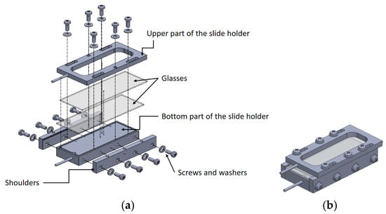
Figure 1.
Slide holder adopted for infiltration cell assembly; (a) exploded view; (b) final CAD model.
This replaces the conventional use of microspheres and adhesives, thereby preventing thickness variability and mechanical distortions caused by shrinkage during glue curing. Using this method, it is possible to obtain capillary infiltration of an LCE precursor mixture at its isotropic transition temperature, followed by UV-initiated photopolymerization and thermal post-curing [13].
This method still requires manual handling during rubbing, slide positioning, spacer placement, and film extraction phases. This reliance on operator skill introduces potential variability and, most importantly, limits overall reproducibility. Furthermore, the system is designed to manufacture one film at a time, which is adequate for prototyping but not for applications needing fast and multiple creation of LCE films. Automating rubbing direction, sliding motion, alignment pressure, and infiltration timing would ensure higher quality, precise slide spacing, and uniform infiltration independently from the operator’s skill [14].
To address this issue, the present work aims to automate the mechanical alignment steps to manufacture LCE films. Instead of attempting to automate the entire chemical fabrication workflow, the system targets the operations most prone to operator error: rubbing, slide manipulation, spacer positioning, and infiltration cell assembly. These steps are mechanized through a dedicated low-cost prototype obtained by customizing a Cartesian robot derived from a 3D printer. By replacing microspheres and adhesive bonding with calibrated metal spacers and magnetic coupling, the framework ensures more controlled and repeatable film geometry. Furthermore, the limited cost of the equipment enables parallel deployment of multiple units, significantly increasing production throughput. It is important to remark that the main intent here is to automate only the mechanical assembly steps (rubbing, spacer placement, slide alignment), while infiltration and polymerization remain semi-manual due to the chemical sensitivity of LCE precursors.
To the best of the authors’ knowledge, there is only one comparable automated system for LCE fabrication reported in the literature, namely the RoboLEC workstation, presented in [15]. Although both approaches rely on modifying the hardware of a commercial 3D printer to automate repetitive laboratory tasks, the objectives, alignment strategies, and levels of mechanical redesign largely differ. RoboLEC is designed to automate photoaligned LCE fabrication, leveraging azopolyimide-coated slides and a laser projector to generate arbitrary director patterns, while also integrating automated glue dispensing, heating, and UV polymerization. In contrast, the system proposed in this work focuses on the mechanical assembly of the infiltration cell, automating the critical steps. Furthermore, whereas RoboLEC aims at producing patterned molecular orientations for micromechanics and soft robotics, the present system targets scalable and low-cost production of uniformly aligned LCE films with controlled thickness. As a result, the two hardware systems address different aspects of the fabrication workflow and respond to distinct material and application requirements.
To contextualize the contribution of the system provided in this paper, Table 1 provides a quantitative comparison with the RoboLEC workstation [15]. In particular, a comparison between the two systems across cost, throughput, alignment quality, and film-thickness consistency is provided in a qualitative manner.

Table 1.
Qualitative comparison between the approach proposed in this work and RoboLCE system [15].
More in detail, the proposed system is not devoted to the automation of the infiltration and polymerization stages, which are still partially manual due to the sensitivity of LCE chemistry to both temperature and curing conditions. Rather, the present work concentrates on the phases where mechanical repeatability has the largest impact on film quality. By stabilizing these steps, the proposed framework lays the groundwork for full automation in LCEs manufacturing.
2. Workflow for the Design of the Automated System
The typical manual manufacturing process of LCE samples consists of six steps [12] (see Figure 2). First, the lower aluminum base is inserted into the 3D-printed support base, which provides a maximum clearance of 0.4 mm and therefore allows only vertical movement. Next, the first slide, previously rubbed and coated with PVA, is placed on the base with the coated side facing upward. The metal spacers are then positioned externally and held in place by the magnets embedded in the metal base, after which the upper support is inserted to guide the positioning of the second slide. The second slide is subsequently placed with the PVA-coated side facing downward. Finally, the upper metal part is installed and magnetically coupled to the lower metal part, bringing the two slides together at the distance defined by the spacers. At this point, the assembled infiltration cell can be removed and transferred onto the heating plate for infiltration followed by UV photopolymerization.
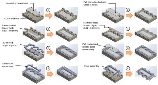
Figure 2.
CAD models of the infiltration cell construction steps.
Each phase requires precise hand coordination to avoid damaging the sacrificial PVA layer, misplacing the spacers, or introducing slight angular deviations that could compromise the uniformity of film thickness and the quality of mesogen alignment. To automate this process a dedicated hardware system is here developed to replicate the process carried out manually by the operator but with more precision. In detail, the required movements allowing to correctly assemble an LCE are the ones depicted in Figure 3.
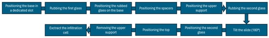
Figure 3.
Movements required to assemble an LCE.
A Cartesian robot was therefore selected to meet the need for high precision and repeatability. As widely recognized, the kinematic structure of this class of robots is typically described as “PPP,” indicating three prismatic joints that provide linear motion along the X, Y, and Z axes through mutually orthogonal slides.
This configuration is widely employed in commercial FDM 3D printers. In this work, the Creality Ender 5 Plus (Creality Inc., Shenzen, China) was chosen as the baseline platform for developing the customized Cartesian system, although other platforms can be adopted as well. Because the purpose of this system is to accelerate the development of multiple LCEs within a limited time frame, it is essential to keep the cost of each manufacturing unit as low as possible to allow parallel operation of many machines. For this reason, a modified 3D printer provides an effective and economical hardware basis that can be readily adapted to the specific production workflow and automated for assembling the infiltration device.
3. Design of the Automated Manufacturing Framework
This section describes the redesign of the infiltration device and the development of the hardware required to assemble it. Based on the limitations identified in the manual process, each component was redesigned to enable automated handling, alignment, and rubbing operations. The following subsections detail the design rationale and implementation of these elements.
3.1. Design of the Manipulator for the Assembly of the LCE Material Infiltration Device
3.1.1. Handling of Device Parts
The analysis of the manual assembly process shows that the components of the device can be coupled primarily through top-to-bottom movements. Based on this observation, a dedicated manipulator was designed, equipped with fork-like end-effectors capable of picking up, transporting, and precisely positioning the individual parts (see Figure 4a). Two different fork geometries were designed to accommodate the specific handling requirements of each component.
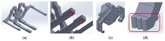
Figure 4.
(a) CAD model of the manipulator; (b) detail of forks; (c) CAD model of the manipulator; (d) detail of magnet slots.
The central forks are aimed at transporting the base and top elements, whereas the outer forks are dedicated to handling the thickness spacer. These were provided with larger cross-sectional dimensions to ensure greater mechanical strength and to minimize bending during the manipulation of the aluminum alloy base and top. In contrast, the outer forks, used to grip the PLA spacer produced via additive manufacturing [16], were designed with a slimmer profile. Both the central and lateral fork assemblies incorporate retaining features that maintain the correct positioning of the components during transport. These constraints are essential, as any mismatch or variation in axis speeds could generate reaction forces capable of shifting the base or top during motion.
The higher thickness of the central forks also ensures the presence of slots on the top to accommodate two magnets of 4 mm diameter and 1 mm thickness, used to engage, transport and correctly position the spacers in the assembly base (see Figure 4b). The manipulator a separate part in order to facilitate its replacement in the event of shocks that could damage one or more of the forks.
3.1.2. Handling of Glass Parts
To enable reliable engagement, transport, and positioning of the slides, a dedicated manipulator was designed by repurposing the stepper motor of the Creality Ender 5 Plus, which was originally intended to feed filament into the extrusion chamber. Since this subsystem was not required for the expected application, it was reassigned to provide an additional degree of motion for the manipulator. To avoid the use of a vacuum pump, and the associated need for suction cups, a mechanical gripper was developed, consisting of one movable jaw and two fixed jaws (see Figure 4c). The movable jaw is capable of rotating up to 35° from the vertical plane, allowing proper engagement with the slide. Contact between the jaws and the component is cushioned by a soft-touch thermoplastic polyurethane (TPU) element produced via additive manufacturing, detailed in Figure 4d. This element features three semicircular profiles designed to ensure contact with the slide at a single tangent point, thereby improving stability and reducing wear. The soft-touch insert is designed as a replaceable component to accommodate progressive material degradation. It is mounted onto the movable jaw through a dedicated slot interface.
The rotation of the moving clamp of the gripper is provided by the stepper motor originally used to feed the filament into the extrusion chamber of the 3D printer. To ensure correct assembly, the fixed clamps were fitted with a radial ball bearing, SKF model 16004, for positioning and movement. It is important to emphasize that the choice of bearing was determined by its geometric characteristics and not by static/dynamic dimensioning, since the forces involved are very low. The housing for the outer ring of the bearing was made in the first fixed jaw (Figure 5a), the one coupled to the printer connection bracket, as shown in Figure 5b. The movable jaw is also provided with an end stop to prevent the risk of damage during assembly. To ensure alignment of the gripping surfaces of the first and second clamp, a slot has been added (Figure 5c) to ensure both correct positioning and correct spacing of the cantilevered parts. Shims have also been added to maintain the correct spacing when the screws are tightened (Figure 5d).
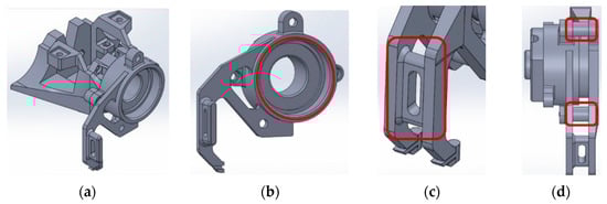
Figure 5.
(a) CAD model of the manipulator–detail of the bearing seat detail; (b) CAD model of the manipulator–detail of the physical end-stop; (c) CAD model of the manipulator–detail of the spacers; (d) shims to maintain correct spacing.
3.1.3. Support with Integrated Motor Housing
The motor originally used to feed filament into the melting chamber of the additive manufacturing system was repurposed to actuate the movable jaw of the gripper. Given the size and weight of the gripper assembly, the motor was positioned between the main manipulator structure and the gripper itself. The resulting configuration is shown in Figure 6a. Placing the motor in a central position enhances stability during operation and prevents imbalances or bending that could compromise the repeatability of the process. To further improve robustness and maintainability, the bracket was designed as a separate component, allowing it to be easily reprinted and replaced in the event of accidental damage.
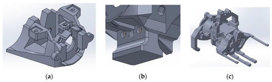
Figure 6.
(a) CAD model for the motor housing; (b) CAD model of the manipulator–detail of the rubbing tool; (c) CAD model of the manipulator.
The purpose of this part is to ensure the correct assembly of the manipulator for the assembly of the fixture and the gripper sub-assembly. In both cases, the connections are disassembled using M4 screws with a cylindrical head and a hexagon socket. As already mentioned, the use of M4 sizes was preferred in order to avoid concentricity problems when inserting the threaded inserts into the housing. To ensure the correct assembly of the manipulator, a centering guide was introduced into the holder.
The final feature to highlight in this section is the housing for the plunger, which applies the coating onto the surface of the slides previously treated with PVA (Figure 6b). Figure 6c shows the complete assembly that interfaces with the Creality Ender 5 Plus 3D printer. Positioning the motor between the gripper and the machine’s handling forks results in a more compact and stable configuration.
Motor mounted in a cantilevered arrangement directly on the gripper would, in fact, result in bending moments would have compromised the precision of the engagement and positioning movements of both the upper and lower slides. This constraint is particularly relevant considering that the structural components are manufactured in PLA, a material with relatively low tensile strength [17].
3.2. Design of the Slde Holder
After the manipulator is designed for the correct assembly of the infiltration device, modifications are required for the slide holder to allow the correct transport of all components.
3.2.1. Slide Holder Base Modifications
The first component of the assembly designed for integration into the automated system is the base. Its function is to elevate the lower glass slide into contact with the spacers through the magnetic force generated by the embedded magnets. Figure 7a,b compares the initial design with the final version after the implemented modifications. The number of magnet housings is reduced from six to four magnet housings. This adjustment was introduced following tests conducted with the original six-magnet configuration, which revealed an unintended effect: when the slides were not positioned correctly, the top element experienced a magnetic attraction strong enough to induce rotation during placement (see Figure 7c).
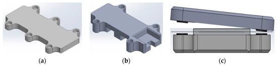
Figure 7.
(a) CAD model of the base slide holder: old version; (b) CAD model of the base slide holder: new design; (c) Base tilt problem.
Although the mechanical loads in this system are low, preliminary force estimations to ensure that the selected magnets, fork thicknesses, and bearing-supported gripper configuration maintain positional accuracy under expected manipulation forces (<0.4 N during slide transport, <1.2 N during rubbing). These calculations guided the choice to reduce the number of magnets from six to four and adjust the fork stiffness to avoid rotational instabilities observed during early prototypes. These design refinements were essential to ensure repeatable positioning across cycles.
In addition, the problem of using six magnets was solved because the device is assembled automatically without any intervention by the operator in charge. To allow the base to be gripped by the manipulator, it was necessary to increase the thickness of the base and to create slots for insertion into those present in the central forks. To avoid collisions with the moving fork of the gripper, a notch was made on the contact surface with the lower base (Figure 8a); in this notch there is a square notch that guarantees the correct positioning of the parts in the shelf, as shown in the following paragraphs (Figure 8b).
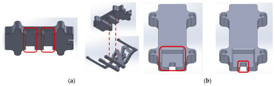
Figure 8.
(a) CAD model of slide holder modifications; (b) Base grip and positioning groove. Red squares highlights main modifications. Red dashed lines indicates the available movement of the parts to be assembled.
3.2.2. Top and Upper Support Redesign
Top and upper supports were also redesigned to be used in automatic machines. The first design modification was aimed at replacing the use of six magnets with only four of them. These, as in the case of the manual device, were aligned with the ones of the base to ensure a surface area of 5 mm for infiltration. To allow the correct insertion of the manipulator for the assembly of the device, it was necessary to increase the thickness of the top and create slots for the insertion of the forks. Figure 9a,b shows the comparison between the initial part and the final result following the modifications introduced. Dealing with the upper support, its purpose is to guide the correct positioning of both the top slide and the top as well as to hold the spacers in place. Figure 9c,d shows the comparison between the initial part and the result following the modifications introduced.
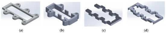
Figure 9.
(a) CAD model of slide holder modifications: old one; (b) CAD model of slide holder modifications: new design; (c) CAD model of slide holder modifications: old one; (d) CAD model of slide holder modifications: new design.
3.3. Design of Supporting Parts for Device Assembly
3.3.1. Shelf for Initial Positioning of Parts
The first redesigned component consists of the shelf with vertical development, aimed to accomplish the initial housing of the base, top and shim. It should be noted that only the first two parts have to be inserted manually by the operator at the beginning of each assembly cycle. The shim, on the other hand, is always the same as it is not present in the final assembly of the device. The result of the design is shown in Figure 10a. The shelf is composed of five elements: the shelf base, which serves as the initial housing for the base; the first shelf, designed to hold the top; and the second shelf, which accommodates the upper support.
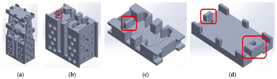
Figure 10.
(a) CAD model of the shelf for initial positioning of parts; (b) slot for the base, (c) slot for the top; (d) slot for the upper support. Red squares highlights the slots used for correctly coupling parts.
The base of the shelf has a slot into which the base of the unit can be inserted in its initial position. An extruded slot was inserted on the first shelf to ensure its correct initial positioning. In terms of thickness, it was decided to also provide a guide for the second shelf in case the operator needed it for replacement or cleaning. These features are shown in Figure 10b–d.
The three parts have slots that act as guides for correct coupling with the lateral shoulders; the base of the shelf and the first shelf have these features on their lateral surfaces (Figure 11a,b), while the second shelf has these features on its internal surface (Figure 11c). For the base of the shelf and the first shelf, 4 mm diameter holes have been drilled, into which threaded inserts for M3 screws have been inserted to tighten the threaded connections for assembly of the parts. A shoulder is shown in detail in Figure 11d; a horizontal shelf was added for the first shelf to provide greater stability. In order to reduce both PLA material and print time, the hexagonal shapes in the base of the shelf were created using the additive technique.
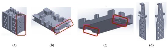
Figure 11.
CAD model of the shelf for initial positioning of parts, detail of (a) slot for base, (b) slot for top, (c) slot for upper support and (d) lateral support. Red squares highlight the designed shoulders.
3.3.2. Design of the Base for Initial Positioning of Slides and Spacers
The upper and lower slides and spacers require the operator to manually insert these at the beginning of each assembly cycle. The result obtained as a result of the design is shown in Figure 12a. There are two main features to highlight on this part: the first concerns the slots present in the slide positioning positions. These, visible in Figure 12b, have the function of eliminating any possible interference between the part and the jaws of the clamp, both fixed and mobile. To avoid positioning errors, the operator is guided through a 0.8 mm deep cut-out when inserting the slide. The remaining features to be considered are the 1.4 mm diameter blind holes for the 1 mm diameter and 5 mm high magnets to hold the spacers in place during initial positioning. To facilitate their insertion, a countersink of 1 mm per 45° has been made. The contact surface of the spacer is also highlighted by a circumferential cut. These features are shown in Figure 12c,d.
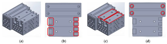
Figure 12.
(a) CAD model of the shelf for initial positioning of slides and spacers. (b) CAD model of the shelf for initial positioning of rails and spacers; (c) detail of the slots for gripper; (d) CAD model of the shelf for initial positioning of rails and spacers. Red squares highlight the main slots designed for correct positioning of the part. Contact surface of the spacer is highlighted by the red circle.
3.3.3. Design of the Support Tool for Rubbing
The automatic machine is also responsible for rubbing the surface of the slides, which is carried out by means of the plunger in the manipulator. In order to keep the slides in the correct position during this phase, a part has been designed to be permanently connected to the printing table, as shown in Figure 13a. As described in the previous paragraph for the initial positioning of the slides, here too there are both the notches to prevent collisions with the jaws of the clamps (Figure 13b) and the notch to keep the slides in the correct position during the rubbing phase. During this phase, both pressure and traction are exerted on the slide: the former is guaranteed by the interposition of a 5 mm thick layer of foam rubber between the plunger fixed to the manipulator and the layer of velvet for rubbing (Figure 13c).
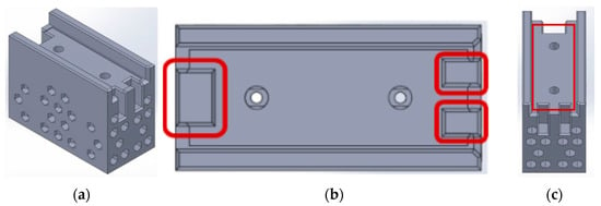
Figure 13.
(a) CAD model of the shelf for the rubbing phase; (b) CAD model of the shelf for the rubbing phase; (c) details of the slots for gripper. Red squares highlight the notches keeping in position the part.
The rubbing force is generated by a prescribed Z-axis displacement and the calibrated stiffness of the 5 mm foam pad, which produces a consistent contact load ranging from 0.5 to 1.0 N. Since the foam experiences gradual compression fatigue (e.g., 100–150 cycles), its response, and therefore the applied pressure, may drift over time, requiring periodic replacement to maintain rubbing consistency.
3.3.4. Slide Flipping Tool
Once the surface of the lower slide has been rubbed, it is possible to proceed with its positioning in the holder; the same procedure cannot be applied to the upper slide. The latter has indeed been rubbed on the upper surface, but inside the base it has to be inserted upside down in order to align it with the lower slide. It was therefore necessary to design a device to turn it upside down, which is moved entirely by the forks in the manipulator. The result is shown in Figure 14a. From this height, the forks use a lateral thrust to guide the slide into the inclined plane from which the complete tipping operation takes place. In order to cushion the impact caused by the rotation, it was decided to insert a 5 mm thick piece of foam rubber, as shown in Figure 14b. Slots allow to prevent the gripper jaws from being struck during the positioning and engagement of the slide (Figure 14c).
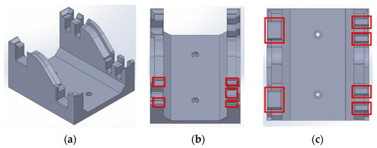
Figure 14.
(a) CAD model of the slide flipping tool, (b,c) detail of the slots for gripper. Slots to prevent the gripper jaws from being struck during the positioning and engagement of the slide are marked with red squares.
3.3.5. Device Assembly Base
The assembly base of the device is modified to ensure the correct automatic positioning of the parts that make-up the assembly. Figure 15a,b shows a comparison between the base for manual use and the one to be inserted into the robot. The first visible difference is the height of the base, which is increased to prevent the forks from colliding when positioning the parts that make up the device. Another visible difference is the presence of slots to prevent collisions with the manipulator, both for the gripper jaws (Figure 15c) and for the forks (Figure 15d). The slots for the 5 mm diameter, 1 mm high magnets that hold the spacers in place are moved outwards because of the need to make the cuts for the forks to move freely. The last part to be fixed to the printing table is the end position base of the assembly, which has a greater height than the assembly base to prevent the manipulator from being hit during movement. Figure 15e shows the end position base of the assembly.
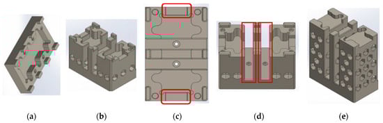
Figure 15.
(a) CAD model of the device assembly base support: old version; (b) CAD model of the device assembly base support: redesigned part; (c) CAD model of the Device assembly base support; (d) detail of the slots for gripper; (e) CAD model of the Base for the final positioning of the infiltration cell. Red squares highlight the modified parts.
3.4. Cost, Process Time and Mechanical Durability of the Automated Framework
As already mentioned, the proposed framework is meant to be low-cost equipment, with the aim of being suitable for parallel deployment. The main hardware components of a single automated workstation are estimates using typical commercial prices from EU online suppliers. As already mentioned, the customized Cartesian platform is based on a Creality Ender 5 Plus 3D printer, whose market price is in the range of 600–700 €. The structural and functional add-ons (fork-like end-effectors, gripper body, shelves, flipping tools, and bases) are manufactured from PLA using approximately 0.5–0.7 kg of filament, corresponding to about 8–15 EUR in material cost.
Additional components include neodymium magnets for slide and spacer retention (on the order of 10–20 EUR for a batch sufficient for multiple devices) and two SKF 16,004 deep-groove ball bearings for the gripper, whose unit price typically lies around 10–15 EUR per bearing. Fasteners, foam pads, velvet rubbing cloth, and minor mechanical hardware contribute an additional ≈30–50 EUR. Summing these items yields an estimated hardware cost of roughly 750–850 EUR per automated station, excluding shared laboratory equipment such as the heating plate and UV lamp, which are common to both manual and automated workflows. Table 2 reassumes the overall costs of the automated equipment.
Table 2.
Approximate hardware cost breakdown for one automated workstation (excluding shared lab equipment).
Dealing with process time, in a manual workflow the assembly of a single infiltration cell typically requires 10–15 min of focused operator time, depending on experience and slide handling accuracy. In contrast, the automated system completes the entire assembly sequence in approximately 3–5 min, including rubbing, spacer placement, slide alignment, and final closure. Because the operator is no longer continuously engaged, a single person can supervise up to 3 automated workstations in parallel. This corresponds to a practical throughput of roughly 30 assembled infiltration cells per hour, compared to 4–6 cells/hour in a manual setting. These estimates highlight that even partial automation of the mechanical alignment stages offers a substantial productivity advantage.
Since the system relies on many 3D printed components it is important to consider the long-term mechanical stability of PLA parts under repeated operation. Three-dimensional printed parts are subjected to creep and reduced dimensional stability under constant loads or temperatures above 40–45 °C. Although the forces exerted during LCE assembly are low (i.e., <1.2 N), repeated cyclic loading at the gripper tips and fork interfaces may lead to progressive deformation after several hundred operating cycles. The TPU soft-touch inserts placed on the gripper jaws (Figure 5d) are also subject to wear due to friction against glass substrates. Empirical observation during prototype testing suggests that replacement may be required after approximately 200–300 cycles to maintain consistent grip quality. The neodymium magnets are subjected to negligible degradation over time, but their housing in PLA may loosen slightly due to repeated magnetic engagement and vibration. This introduces a secondary source of drift in alignment pressure that should be monitored. For these reasons, periodic inspection and recalibration are deemed necessary. Based on the cycle counts observed during validation tests, a maintenance schedule would involve the visual inspection of forks, magnet housing, and gripper inserts every 100–150 cycles. Moreover, it is expected to replace, or reprint, high-contact PLA components every 1000 cycles. Full positional recalibration of the robotized axes every 200–300 cycles is also suggested to compensate for minor shifts in component geometry or guide-rail tolerances.
4. Assembly of the Automated Framework
Once all devices are redesigned, it is possible to assemble the infiltration device according to the following steps. These steps are described in Appendix A together with a video of the manufacturing process (see Supplementary Material File).
5. Results
To assess the repeatability of the developed system, ten fabrication cycles under identical conditions and evaluated variability in both geometric and optical outputs were tested. The primary goal of these trials was not to perform a complete statistical analysis but rather to provide functional validation; accordingly, this small dataset allows us to quantify repeatability across the automated sequence.
For the tests, once the cell has been constructed by the Cartesian robot, it is placed on a temperature-controlled plate at 65 °C, together with the flask containing the mixture.
After checking the actual temperature of the cell with the thermal imaging camera in Figure 16a, small amounts of the mixture are collected with a metal rod and placed in the infiltration site of the cell. Infiltration front progresses through 25% of channel length every ~7 min (Figure 16b). After about half an hour, the cell is completely infiltrated and the cooling phase begins to bring the cell to a temperature of 40 °C, which is necessary for the first treatment with ultraviolet light. After 20 min, the temperature is checked with the same camera and the correct value is verified, and the UV lamp is switched on for 10 min (Figure 16c). Next, the cell is brought to a temperature of 65 °C for the second ultraviolet light polymerization treatment, for a further 10 min. The first exposure to the lamp is the most important one: in fact, the temperature at which polymerization of the film takes place must be kept under control [18]. At the end of the second exposure to the lamp, the cell is allowed to cool for 5 min, after which the film is removed from the cell and evaluated for crystal linearity and birefringence (Figure 16d).
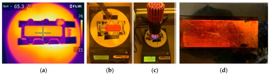
Figure 16.
Procedure for infiltration; (a) check with thermal imaging camera; (b) infiltration of correct material; (c) UV polymerization; (d) result of polymerization.
It is important to highlight that none of the PLA structural components of the automated workstation are exposed to temperatures approaching their glass transition temperature (typically around 55–60 °C). During the LCE curing process, only the infiltration cell is transferred to the external heating plate and UV-curing station, while the robot and its PLA-printed fixtures remain thermally isolated from the heated environment. As a result, the PLA parts experience only ambient-temperature operation, ensuring dimensional stability and mechanical integrity throughout repeated manufacturing cycles. For LCE chemistries requiring higher curing temperatures (e.g., up to 80 °C), the heating occurs entirely off-board, and the robot does not undergo thermal loading.
In the initial LCE production trials, the films were misaligned and showed inconsistencies in transparency and final color, as shown in Figure 17. The causes can be attributed to two main factors:
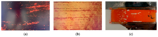
Figure 17.
(a) Example of properly aligned LCE. (b) example of misalignment, i.e., uneven distribution of LCE (c) Example of an LCE with bubbles inside.
- The rubbing step with the Cartesian robot was not performed correctly, creating microchannels that were not aligned with respect to the liquid crystal alignment plane, or applying insufficient pressure.
- The temperatures set on the thermal plate did not match the actual temperatures, significantly altering the temperatures required for the UV curing steps. The use of the thermal imaging camera revealed a temperature difference between the hot plate temperature and the actual temperature of approximately T = +5 °C, which resulted in the first polymerization step being performed at a cell temperature too close to the transition temperature.
In particular, the first has little effect on color, unlike the second, which affects the refraction of light. In some cases, there is no refraction at all, while in others it occurs in random areas of the elastomer. During the infiltration phase, another potential defect can occur: the formation of air bubbles in the LCE film. These bubbles form as a result of the uneven distribution of the compound in the alignment plane and cannot be filled once formed.
To avoid the possible formation of bubbles within the film, a stirring rod is used to stimulate the points where a difference in the flow of the mixture is observed on the infiltration plane. Modifications were then made to the Cartesian robot for the rubbing phase and temperatures were corrected. To test the repeatability of the apparatus, ten infiltration cells were made (i.e., ten films were produced). The thickness of each film was measured at fifteen different positions (P1–P15) as shown in Figure 18, using a micrometer with a measurement sensitivity of 0.001 mm. The film is placed between two disks to ensure its stability. Each measurement was repeated three times, and the average was calculated. Knowing the thickness of each disk, the thickness of the film is obtained by a simple difference between the two, with an uncertainty corresponding to the sensitivity of the instrument. The results of the measurements of the films produced by the spacer with a nominal thickness of 0.020 mm are shown in Table 3. To provide a clearer statistical representation of the thickness data reported in Table 3, Figure 19 shows the mean thickness of each of the ten fabricated LCE films together with their corresponding standard deviations. Each bar represents the average value obtained in the fifteen measurement points per sample, while the error bars denote the standard deviation obtained from the three repeated measurements at each point. This visualization highlights the intra-sample variability (standard deviations in the range of 0.0024–0.0047 mm), confirming that the automated assembly process produces geometrically consistent films. The bar chart also makes evident that inter-sample differences arise primarily from the systematic offset between the nominal spacer thickness (0.020 mm) and the actual substrate-defined gap, rather than from stochastic variation in the robotic assembly.
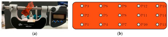
Figure 18.
(a) Micrometer to measure film thickness; (b) reference points.
Table 3.
Results of the measurements of the films produced by the spacer with a nominal thickness of 0.020 mm.
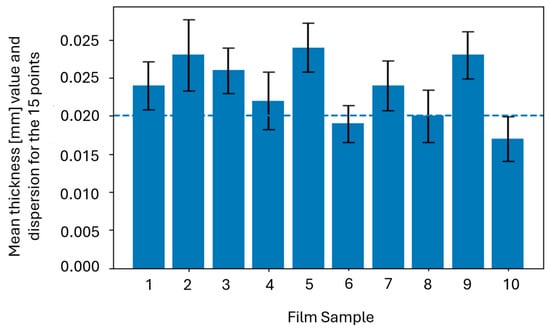
Figure 19.
Mean thickness and standard deviation of the ten LCE films produced with the automated framework. The blue dashed line indicates the nominal spacer thickness (0.020 mm).
It is important to highlight that the deviation between spacer thickness and final film thickness does not occur because of the automated assembly but, rather, from substrate variability that the automated system is not able to compensate. Therefore, the results in Table 3 also emphasize how the available commercial slides are affected by error.
In fact, the correlation between local slide thickness and film thickness confirms that the developed machine is able to preserve the geometry imposed by the substrates reliably. It can also be seen that the average thickness of the films differs from the nominal thickness of the spacers. Therefore, it was decided to investigate the causes of this phenomenon by measuring the thickness of the laboratory slides after PVA coating. As with the films, the glass was measured at fifteen points, as shown in Figure 18. The measurements were repeated three times, and the average was then calculated and shown in Table 4.
Table 4.
Glass slide thickness.
From the measurements shown in Table 4, the laboratory slides have average dimensions and deviations in line with the desired film thickness. Figure 20 highlights how each slide’s mean thickness differs from the nominal value equal. This shows that small slide-to-slide deviations (on the order of a few micrometers) are sufficient to influence the final LCE film thickness despite the high repeatability of the automated assembly process.
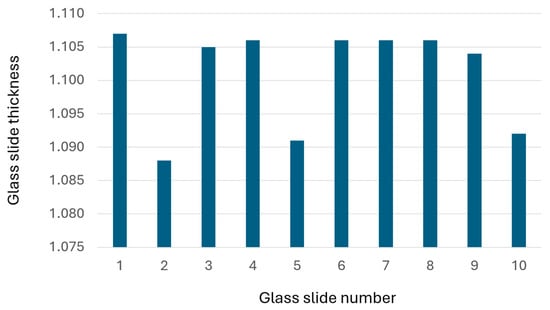
Figure 20.
Mean thickness of the ten PVA-coated glass slides, measured on the fifteen measurement points per slide. The plot highlights inherent substrate-to-substrate variability, which contributes significantly to the final film-thickness deviation observed in the automated LCE fabrication process.
To further validate the performance of the automated manufacturing framework and to distinguish robot-induced variability from substrate-induced effects, three additional quantitative analyses were carried out: (1) statistical correlation between slide thickness and final film thickness, (2) assessment of positional repeatability of the Cartesian manipulator, and (3) quantification of rubbing-induced microgroove uniformity.
As shown in Table 3 and Table 4, both the PVA-coated slides and the resulting LCE films exhibit spatial thickness variations. To assess whether the film-thickness deviations originate from substrate geometry rather than from robotic assembly, a Pearson correlation analysis [19] was carried out. The evaluated correlation coefficient was found to be equal to r = 0.78, indicating a positive relationship between local slide thickness and local film thickness, and comparable with scientific literature values [20,21].
This is sufficiently in accordance with the maps presented in Figure 21, which show, as an illustrative example, thickness gradients for 6 out of 10 glasses. Values, for the whole set of 10 samples, are in the order of 10–15 µm across a single slide. In the figure, the color bar on the right-hand side refers to thickness value, while the bottom color bar refers to the deviation from the average value.
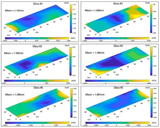
Figure 21.
Plots of 6 out to 10 measured glass slides. Vertical color bar represents the absolute measured slide thickness in millimeters, while the horizontal color bar indicates the local deviation from the mean thickness of the slide.
With the corrected setup, quantitative measurements were then carried out to distinguish the contributions of substrate variability from those introduced by the robotic assembly. The repeatability of the machine was evaluated by recording the end effector position at different stages: slide gripping, spacer placement, rubbing engagement, and final cell closure. In particular 20 cycles were tested; infiltration was not performed during the tests. The higher positional variation in the machine resulted equal to ±0.08 mm in the XY plane and ±0.05 mm in Z. These values are quite consistent with the mechanical tolerances of the Ender 5 Plus platform [22] and are lower than the thickness variation listed in Table 4. The standard deviation of slide seating position within the lower holder was approximately equal to 0.07 mm, confirming that the system introduces low drift over time.
To assess the uniformity of surface microgrooves generated by the automated rubbing system, coated slides were analyzed using polarized optical microscopy. For each slide, intensity profiles were extracted along the rubbing direction. For each pixel, the transmitted intensity varies according to the well-known relation , where is the angle between the LC director and the polarizer axis [23]. By acquiring two intensity fields and , the director angle can be estimated through the ratio of the two measurements.
Figure 22 shows contour map of the local LC director orientation [24] extracted from polarized optical microscopy images acquired at 0° and 45° between crossed polarizers. The color scale represents the orientation angle , showing a nearly uniform director field with small, localized deviations.
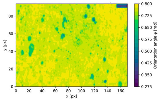
Figure 22.
Contour map of the local LC director orientation extracted from polarized optical microscopy images acquired at 0° and 45° between crossed polarizers.
Automated rubbing produced patterns with a coefficient of variation consistently below 7%, indicating stable groove orientation and depth across the entire rubbed region. These results can also be visually evaluated as demonstrated in Figure 23a,b, where films remain substantially dark at 0° and bright at 45°, demonstrating appropriate mesogen orientation throughout the sample. In comparison, manually rubbed slides typically exhibited intensity variation higher than 12%, mostly due to inconsistent pressure and stroke orientation (see Figure 23c,d).
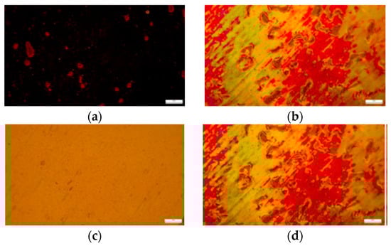
Figure 23.
(a,b) correctly aligned LCE; (c,d); incorrectly aligned LCE.
Even though the substrate variability remains a limiting factor, the automated system reduces operator-dependent sources of error, including rubbing pressure, alignment angle, slide overlap, and spacer placement. These are significant contributors to misalignment and film defects in manual fabrication.
It is important to remark that the dataset of ten fabricated films is intended as a functional validation of the automated workflow rather than a full statistical demonstration of scalability. In fact, the limited sample size does not permit high-confidence inferential statistics, but the collected measurements highlight that the dominant source of thickness variation originates from substrate irregularity rather than from robot-induced errors. This interpretation is supported by the strong correlation between local slide thickness and final film thickness as well as by the measured positional repeatability of the Cartesian system, whose variability remains below the magnitude of the substrate-driven deviations. To further strengthen the repeatability analysis, as already mentioned, 20 more assembly cycles were run to quantify robotic positioning variability. Measured values for position remained in the range ±0.08 mm in the plane XY and ±0.05 mm in Z. Rubbing uniformity analysis, again assessed by using polarized optical microscopy demonstrated a coefficient of variation below 7% thus confirming stable microgroove geometry. These metrics further confirm thickness non-uniformity, rather than robotic misalignment, as the dominant factor affecting final film thickness.
6. Conclusions
This study introduced an automated manufacturing framework for Liquid Crystal Elastomer films, aimed at overcoming the reproducibility, precision, and scalability limitations inherent to traditional manual fabrication.
By analyzing each phase of the manual process, i.e., rubbing, slide handling, spacer positioning, infiltration cell assembly, and post-processing, a comprehensive redesign of the infiltration device components is provided. Moreover, this work described the integration of these redesigned elements into a customized Cartesian robotic platform derived from a modified Creality Ender 5 Plus system. The developed system incorporates dedicated mechanical subsystems, including fork-based end-effectors for base, top, spacer manipulation, mechanical gripper for glass slide engagement, a redesigned set of magnetic slide holders optimized for robotic interfacing, a modular alignment shelf for initial component arrangement, a dedicated rubbing station for consistent microgroove generation, and a servo-free flipping mechanism enabling automatic inversion of the upper slide.
These components allow executing all assembly operations with reduced operator involvement and high spatial repeatability. The modifications also limit several issues typically raised from manual fabrication, such as uneven spacer adhesion, misalignment during placement, and the presence of borosilicate microspheres embedded in the final film. Experimental validation confirms that the automated platform correctly automates the mechanical alignment steps crucial for LCE fabrication and supports thermally controlled infiltration and UV-initiated polymerization steps. When coupled with corrected thermal plate calibration, the system produces films exhibiting good-quality nematic alignment, as evidenced by polarized optical microscopy: films remain dark at 0° and bright at 45°, indicating proper mesogen orientation across the entire sample [25]. Ten fabricated films were analyzed to assess manufacturing repeatability. Results show that while the alignment quality is consistent, the final film thickness deviates from the nominal spacer dimension. Subsequent metrological inspection revealed that these deviations are primarily attributable to thickness non-uniformity of the PVA-coated glass slides, which directly impacts the achievable precision of the LCE layer, despite the mechanical accuracy of the robot.
Overall, the automated system demonstrates improvements in reliability, geometrical repeatability, contamination avoidance, and quality of liquid-crystal alignment compared to manual fabrication. Beyond improving fabrication accuracy, the possibility to operate multiple low-cost units in parallel expands the practical availability of LCE films for research laboratories. This scalability is relevant for fields where iterative testing, device integration, or characterization of LCEs is required, enabling experimental workflows that are currently impractical with manual fabrication.
Although automation improves geometric repeatability, results in Table 3 and Table 4 demonstrate that substrate thickness variations persist as the principal source of error. This issue can be mitigated by pre-screening slides through automated micrometer or interferometric mapping and by implementing an adaptive Z-compensation mechanism in the spacer region. Future versions of the framework will incorporate these solutions to reduce film thickness variability.
In detail, the analysis of the film thickness data (Table 3) in combination with the slide-thickness maps (Table 4 and Figure 21) demonstrates that the principal limitation to thickness uniformity is the intrinsic geometric variability of commercially available glass slides, which often exhibit local deviations of 10–15 µm. These values are comparable to or larger than the nominal film thickness itself. Since the automated assembly produces highly repeatable positioning (as already stated, varying in the range ±0.08 mm in XY, ±0.05 mm in Z), the dominant error clearly arises from substrate irregularity rather than from the robotics workflow. To improve the precision of the final LCE films, several substrate-oriented interventions can be implemented. By way of example, a preliminary characterization and sorting step can be integrated into the workflow, wherein the robot (or a low-cost profilometer) measures thickness at multiple points- Slides exceeding a predefined tolerance threshold are automatically rejected or assigned to applications requiring lower precision.
For more advanced automation, the system could incorporate adaptive Z-axis compensation, in which the robot adjusts the spacer offset or introduces micro-shimming based on a thickness map computed during slide loading.
Future works will also be devoted to the mitigation of external causes of thickness variability, in further improving thermal compensation during polymerization, and extending automation to post-curing, cutting, and mechanical-electrical characterization of the films. These enhancements could be useful to advance the system toward a fully autonomous, high-throughput manufacturing platform capable of supporting emerging applications such as artificial muscles, adaptive optics, and soft actuator arrays.
Eventually, the integration of systematic mechanical testing to assess the tensile response and stress director coupling of the films produced by the automated framework will also be planned for the future. In fact, the present study focuses on automating the assembly steps that most strongly influence geometric uniformity and molecular alignment; therefore, a rigorous evaluation of mechanical performance requires additional process refinements, including standardized specimen preparation, controlled cutting along the director, and fully calibrated thermal curing protocols. As these elements are currently being optimized and incorporated into the workflow, tensile characterization will be conducted in a subsequent phase to verify the consistency of modulus, ultimate stress, strain at break, and viscoelastic behavior across different batches.
Supplementary Materials
The following supporting information can be downloaded at: https://www.mdpi.com/article/10.3390/designs10010003/s1.
Author Contributions
Conceptualization, L.G. and A.P.; methodology, A.P.; validation, R.F. and M.C.; formal analysis, A.P. and R.F.; investigation, L.G.; data curation, M.C.; writing—original draft preparation, R.F.; writing—review and editing, R.F.; project administration, L.G.; funding acquisition, L.G. All authors have read and agreed to the published version of the manuscript.
Funding
This research was funded by the European Union’s Horizon 2020 research and innovation programme under grant agreement No 952166 (REPAIR).
Data Availability Statement
The raw data supporting the conclusions of this article will be made available by the authors on request.
Conflicts of Interest
The authors declare no conflicts of interest.
Appendix A
Step 1: positioning the various parts of the Space Holder V2: base, top, top holder, PVA coated slides and spacer.

Step 2: Base engagement and positioning

Step 3: lLower glass engagement, rubbing and positioning of the base

Step 4: Spacer engagement and positioning

Step 5: Engagement and positioning of Top holder

Step 6: Upper slide engagement, rubbing, tilting and positioning on the base

Step 7: Engagement of the top and positioning it over the two slides, removal of the support, and removal of the infiltration cell

References
- Herbert, K.M.; Fowler, H.E.; McCracken, J.M.; Schlafmann, K.R.; Koch, J.A.; White, T.J. Synthesis and Alignment of Liquid Crystalline Elastomers. Nat. Rev. Mater. 2022, 7, 23–38. [Google Scholar] [CrossRef]
- Ambulo, C.P.; Tasmim, S.; Wang, S.; Abdelrahman, M.K.; Zimmern, P.E.; Ware, T.H. Processing Advances in Liquid Crystal Elastomers Provide a Path to Biomedical Applications. J. Appl. Phys. 2020, 128, 140901. [Google Scholar] [CrossRef]
- Zhang, W.; Nan, Y.; Wu, Z.; Shen, Y.; Luo, D. Photothermal-Driven Liquid Crystal Elastomers: Materials, Alignment and Applications. Molecules 2022, 27, 4330. [Google Scholar] [CrossRef]
- Kularatne, R.S.; Kim, H.; Boothby, J.M.; Ware, T.H. Liquid Crystal Elastomer Actuators: Synthesis, Alignment, and Applications. J. Polym. Sci. B Polym. Phys. 2017, 55, 395–411. [Google Scholar] [CrossRef]
- Liu, Y.; Ma, J.; Yang, Y.; Valenzuela, C.; Zhang, X.; Wang, L.; Feng, W. Smart Chiral Liquid Crystal Elastomers: Design, Properties and Application. Smart Mol. 2024, 2, e20230025. [Google Scholar] [CrossRef]
- Hussain, M.; Jull, E.I.L.; Mandle, R.J.; Raistrick, T.; Hine, P.J.; Gleeson, H.F. Liquid Crystal Elastomers for Biological Applications. Nanomaterials 2021, 11, 813. [Google Scholar] [CrossRef] [PubMed]
- Thomsen, D.L.; Keller, P.; Naciri, J.; Pink, R.; Jeon, H.; Shenoy, D.; Ratna, B.R. Liquid Crystal Elastomers with Mechanical Properties of a Muscle. Macromolecules 2001, 34, 5868–5875. [Google Scholar] [CrossRef]
- Vitale, G.; Grandinetti, B.; Querceto, S.; Martella, D.; Tesi, C.; Poggesi, C.; Cerbai, E.; Wiersma, D.K.; Parmeggiani, C. Photoresponsive Polymer-Based Biomimetic Contractile Units as Building Block for Artificial Muscles. Macromol. Mater. Eng. 2022, 307, 2200187. [Google Scholar] [CrossRef]
- Varghese, S.; Crawford, G.P.; Bastiaansen, C.W.M.; De Boer, D.K.G.; Broer, D.J. Microrubbing Technique to Produce High Pretilt Multidomain Liquid Crystal Alignment. Appl. Phys. Lett. 2004, 85, 230–232. [Google Scholar] [CrossRef]
- Yamahara, M.; Nakamura, M.; Koide, N.; Sasaki, T. Influence of Rubbing Conditions of Polyimide Alignment Layer on Optical Anisotropy of Immobilized Liquid Crystal Film. Liq. Cryst. 2007, 34, 381–387. [Google Scholar] [CrossRef]
- Zhai, Y. Design Guidelines of Printing Processes to Improve Electrical and Mechanical Properties for Haptics and Robotics. Ph.D. Thesis, University of California San Diego, San Diego, CA, USA, 2021. [Google Scholar]
- Profili, A.; Di Iorio, F.; Aasmul, S.; Governi, L. Design and Development of a Liquid Crystal Elastomers Infiltration Prototype. In Proceedings of the International Conference of the Italian Association of Design Methods and Tools for Industrial Engineering, Palermo, Italy, 11–13 September 2023; Springer Nature: Cham, Switzerland, 2023; pp. 441–448. [Google Scholar] [CrossRef]
- Corbett, D.; Warner, M. Changing Liquid Crystal Elastomer Ordering with Light—A Route to Opto-Mechanically Responsive Materials. Liq. Cryst. 2009, 36, 1263–1280. [Google Scholar] [CrossRef]
- Guin, T.; Settle, M.J.; Kowalski, B.A.; Auguste, A.D.; Beblo, R.V.; Reich, G.W.; White, T.J. Layered Liquid Crystal Elastomer Actuators. Nat. Commun. 2018, 9, 2531. [Google Scholar] [CrossRef]
- Grabowski, P.; Fabjanowicz, B.; Podgórska, M.; Rogóż, M.; Wasylczyk, P. Automated Photo-Aligned Liquid Crystal Elastomer Film Fabrication with a Low-Tech, Home-Built Robotic Workstation. Sci. Rep. 2022, 12, 17598. [Google Scholar] [CrossRef]
- Odera, R.S.; Idumah, C.I. Novel Advancements in Additive Manufacturing of PLA: A Review. Polym. Eng. Sci. 2023, 63, 3189–3208. [Google Scholar] [CrossRef]
- Fontana, L.; Minetola, P.; Iuliano, L.; Rifuggiato, S.; Khandpur, M.S.; Stiuso, V. An Investigation of the Influence of 3D Printing Parameters on the Tensile Strength of PLA Material. Mater. Today Proc. 2022, 57, 657–663. [Google Scholar] [CrossRef]
- Mucha, M. Polymer as an Important Component of Blends and Composites with Liquid Crystals. Prog. Polym. Sci. 2003, 28, 837–873. [Google Scholar] [CrossRef]
- Sedgwick, P. Pearson’s correlation coefficient. Bmj 2012, 345, e4483. [Google Scholar] [CrossRef]
- Wang, Z.; Wang, Z.; Zheng, Y.; He, Q.; Wang, Y.; Cai, S. Three-dimensional printing of functionally graded liquid crystal elastomer. Sci. Adv. 2020, 6, eabc0034. [Google Scholar] [CrossRef]
- McCracken, J.M.; Hoang, J.D.; Herman, J.A.; Lynch, K.M.; White, T.J. Millimeter-Thick Liquid Crystalline Elastomer Actuators Prepared by-Surface-Enforced Alignment. Adv. Mater. Technol. 2023, 8, 2202067. [Google Scholar] [CrossRef]
- Betts, J.L.; Sampson, B.J.; Lindsey, K.; Brinkley, F.M.; Priddy, M.W. Reduction of Process Induced Porosity for Ultrafuse 316 L through Parameter Optimization of Creality Ender 3 V2 and Makerbot Method X. Crystals 2024, 14, 285. [Google Scholar] [CrossRef]
- Wei, C.; Cao, S.; Zhou, Y.; Lin, D.; Jin, L. Rate-dependent stress-order coupling in main-chain liquid crystal elastomers. Soft Matter 2023, 19, 7923–7936. [Google Scholar] [CrossRef] [PubMed]
- Gleeson, H.F.; Wood, T.A.; Dickinson, M. Laser manipulation in liquid crystals: An approach to microfluidics and micromachines. Philos. Trans. R. Soc. A Math. Phys. Eng. Sci. 2006, 364, 2789–2805. [Google Scholar] [CrossRef] [PubMed]
- Kim, K.; Guo, Y.; Bae, J.; Choi, S.; Song, H.Y.; Park, S.; Ahn, S.K. 4D printing of hygroscopic liquid crystal elastomer actuators. Small 2021, 17, 2100910. [Google Scholar] [CrossRef] [PubMed]
Disclaimer/Publisher’s Note: The statements, opinions and data contained in all publications are solely those of the individual author(s) and contributor(s) and not of MDPI and/or the editor(s). MDPI and/or the editor(s) disclaim responsibility for any injury to people or property resulting from any ideas, methods, instructions or products referred to in the content. |
© 2025 by the authors. Licensee MDPI, Basel, Switzerland. This article is an open access article distributed under the terms and conditions of the Creative Commons Attribution (CC BY) license.