Abstract
The idea of an extension of life for CubeSats is proposed to reduce space debris in a low-earth orbit. In this work, a gripper is designed for geometry-based grasping in berthing tasks. The grasping operation is outlined for square- and rectangle-shaped CubeSats. Equilibrium conditions are formulated to design the fingertips’ shape and parameters for grasping CubeSat bodies. A design scheme is proposed to provide the required accuracy. A design concept is developed into a lab prototype by using low-cost 3D printing manufacturing, and a mock-up grasping task that is representative of the berthing operation is evaluated with the lab prototype. Center-mass hanging setup for the prototype and grasped body is used to evaluate the impact of grasping, partially replicating the conditions in space by reducing the effect of gravity on the system.
1. Introduction
The number of satellites in orbit increases every year, although a satellite is designed for a limited mission time. Non-functioning satellites become uncontrollable space debris, which are a threat to working ones. Therefore, the probability of a chain reaction of collisions increases with every satellite launch, as discussed by Kessler more than 40 years ago [1]. Currently, the only way to avoid space debris is to burn satellites in the atmosphere at the end of their mission [2]. For higher attitude orbits, a graveyard orbit is set as an alternative.
Another more sustainable way to decrease the number of debris, however, is to prolong the life of satellites. In low-earth orbits, satellites lose their attitude faster than in higher orbits because of the stronger atmospheric influence. It is possible to prolong the lifetime of a satellite by moving it to a higher attitude. The process of space systems maintenance is called “on-orbit servicing” (OOS). However, maintenance on potentially working satellite with no crucial malfunctioning (for example, out of fuel) is cost-effective [3]. An OOS system includes a base or servicing satellite with a manipulator installed on it, a grasping end-effector at the extremity of the manipulator, and a target satellite to be maintained. A successful example of a working OOS system is the International Space Station (ISS). During its more than twenty years of life, several service operations have been conducted. Currently, three manipulators are in use on the ISS, namely, SSRMS or Canadarm2 [4], JEMRMS [5], and ERA [6]. Thanks to their considerable size, they can manipulate objects up to 116,000 kg (with the Canadarm2). They are used to inspect the ISS and moving spacecraft modules.
To maintain spacecraft, robotic systems for extravehicular activity (EVA) are being developed and tested too. With ETS-VII [7], the Japanese Space Agency tested on-orbit service technologies, such as monitoring other satellites, docking, refueling, and replacement of parts. The German Space Agency (DLR) worked in collaboration with the Russian and Canadian Space Agencies (Roscosmos and CSA, respectively) in the TECSAS project [8] and DAPRA Orbital express mission [9]. These projects aimed to prolong the lifetime of existing satellites by refueling them or replacing their components. The deorbiting of a nonfunctioning satellite is planned in a DLR project called DEOS [10]. The OOS satellites, as in [7,8,9,10], were designed with a single manipulator, but multi-arm robotic systems can be used for yet more complex tasks. Examples of these types of systems were proposed in the Advanced Telerobotic Manipulator System (ATLAS) project [10], in kinematic models proposed by Moosavian and Papadopoulos [11] (two-arm systems), and in the TORVEASTRO project [12,13] (a three-link system for EVA in ISS). Repair or change of small modules is still conducted by astronauts. Projects were proposed also for humanoid robotic systems in space, such as Justin from DLR [14], Robonaut 2 [15] from NASA, and Fyodor from RSA [16].
Most of the other systems for OOS [8,10] use peg-in-hole mechanisms to capture the satellites by using their nozzle. This process relies on being able to insert a pin or a similar end-effector (from the gripper) into a corresponding hole on the grasped object but requires a certain degree of accuracy which can be a challenging requirement and is not always possible.
OOS operations involve grasping tasks which, in general, are conducted by grippers. OOS systems in [3,4,5,6,7,8,9,10,11,12,13,14,15,16] refer mostly to manipulation or control tasks. General grasping formulation and types of grasping and grippers are discussed in a large literature whose works [17,18] are significant examples of the topic of this paper. The application of grasping in space conditions is represented in an example of an adaptive three-finger system [19], and example of a dexterous gripper in [20].
CubeSats are a new type of microsatellite [21]. Their small standard size and weight, as well as simplicity when compared with large satellites, made them widely popular. They are used in many fields, such as telecommunication, meteorology, and scientific research. In general, CubeSats are based in low-earth orbit, which, nevertheless, is also occupied by other types of satellites [2]. In low-earth orbit, atmosphere slows satellites, making them lose attitude and burn in atmosphere. Most of the CubeSats are designed without a propulsion system for orbit correction, but a service satellite with an active propulsion system can move a CubeSat to higher attitudes and prolong its lifetime.
For the OOS, the target satellite should be reachable by the base satellite with far- and close-range rendezvous maneuvers and it can be captured. The process of capturing and fixing the target satellite into the special port is called berthing [22]. Currently, berthing is widely used in the ISS for large manned and unmanned satellites, such as Dragon or Progress, with a berthing port of about 1 m [23]. With dimensions 10 cm for 1U (U is indicated as size unit), CubeSat satellites are small enough for existing berthing port designs. Most of the other systems for OOS [8,10] use peg-in-hole mechanisms to capture satellites by their nozzle; others use small grippers to hold a satellite by its solar panels or special flanges.
Most CubeSats do not have nozzles, flanges, and ports for berthing, as shown in Figure 1. Using the open solar panels risks damaging them during the berthing process.
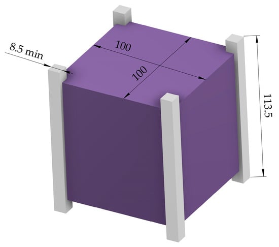
Figure 1.
A schematic design of a CubeSat 1U with dimensions.
In this paper, a novel design of a space berthing end-effector for grasping CubeSats with standard dimensions from 1U to 12U is proposed based on the geometry characteristics of CubeSat designs. A specific grasping is analyzed for the berthing task with CubeSats. The characteristic operation is characterized successfully by experimental tests with properly shaped fingertips and their adjustable grasping configuration.
2. Materials and Methods
2.1. Problems and Requirements
According to the Nanosatellite and CubeSat database [24], 3163 out of 3627 nanosatellites are CubeSat satellites with the U design shape, and 41% of these satellites are designed in 3U size, as summarized in Figure 2 [24].
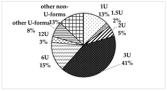
Figure 2.
A chart of distribution CubeSat satellites by types [24].
The problems for a gripper design and operation in berthing tasks with CubeSat satellites (in short CubeSats) can be summarized as follows:
- Geometry-based grasping of CubeSats;
- Keeping the CubeSat after grasping;
- Minimization of mass and inertial characteristics of the gripper;
- Lightweight and low-cost solution for terrestrial testing.
In previous works [25,26], geometry-based grasping is planned along CubeSats’ diagonal ribs by using L-shaped fingertips. In general, CubeSats are not designed with docking or berthing ports, but their shape and dimensions are standardized. A gripper design can be based on its geometry so that a standard grasping can be planned for these types of satellites.
After grasping, a CubeSat should be firmly kept by the gripper and not slip out from its fingertips while being transferred to the berthing port. The grasping force in this case should be large enough to keep the CubeSat and to avoid its slip, but small enough to not damage it. The berthing operation outlined in [25,26], also considers keeping multiple satellites on the base station and using one manipulator only. Therefore, berthing ports based on CubeSats’ geometry are required to be on the base station. Around half of CubeSats use foldable structures such as solar panels or antennas. Unfolded elements of CubeSat can prevent it from being grasped or entering in the berthing port.
CubeSats’ body dimensions do not exceed 36 centimeters in size and 24 kg in mass [21]. For such small satellites, both the manipulator and the gripper can be designed with suitable mass and dimensions and make the base station for maintaining CubeSats cost-efficient. Manipulators such as Canadarm2 [4] with Dextre or ERA [6], with their size, mass, and complexity, are overengineered for this task. Focusing on the berthing can help minimize the mass and inertia characteristics of the gripper. A folding gripper structure is one of the ways to reduce volume in the launcher spacecraft. To reduce development costs, a prototype for preliminary testing of grasping mechanics can be designed using low-cost materials and manufacturing techniques such as 3D-printing.
2.2. Grasping Analysis
To find a suitable gripper configuration, a typical static planar task is presented in Figure 2 in different ways of contact between the grasped body and the gripper fingertip. A square-shaped CubeSat is considered as a grasped body in the presented berthing task. The mass center K with the coordinate system Kxy is placed in the center of the square with the side equal to a. It is assumed that a CubeSat is in contact with fingertips with forces Fh from the grasping surface. Three types of contact can be considered in this task as summarized in Figure 3. The first is an L-shaped fingertip presented in Figure 3a in which contacts with the grasped body are in its corner. The grasping forces Fh to act from the contact point along the sides of the grasped body. The planar fingertip grasping by the middle of the side of the body is presented in Figure 3b with the force Fh. The planar fingertip contact by the edge of the side of the body with the force Fh is shown in Figure 3c.
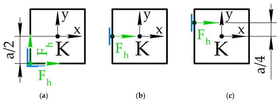
Figure 3.
A grasping task scheme: (a) a corner fingertip configuration; (b) a middle-side fingertip configuration; (c) an edge-side fingertip configuration.
These types of contact can be used in different combinations and are applied to the different corners and sides of the grasped body. According to [17], static equilibrium can be ensured with only two contact points. The sum of forces and moments acting on the body is equal to zero, which is a representation of the equilibrium condition.
To balance the forces, two similar fingertips should act to the opposite sides of the grasped body. For example, two L-shaped fingertips from Figure 3a should act on the opposite corners of the grasped body, as shown in Figure 4a. The same condition is applied for the fingertips in Figure 3b,c, which is given in Figure 4b,c, respectively.
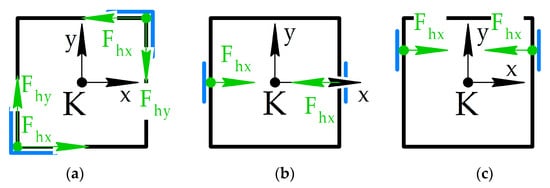
Figure 4.
Two-fingertip grasping combinations from Figure 2: (a) two corner fingertips; (b) two middle-side fingertips; (c) two edge-side fingertips.
Different combinations give unbalanced forces or moments acting on the grasped body. The static equilibrium conditions for three means of contact for fingertips from Figure 4a–c, named FT3a, FT3b, and FT3c, respectively, can be expressed as follows.
For FT3a:
For FT3b:
For FT3c:
In Equations (1)–(3), the grasping forces Fhx and Fhy keep the grasped body inside, i.e., between the two fingertips. This configuration is useful also because the ribs of the body are considered rigid, and it is possible to apply large Fh to ensure that the object retains its grasping configurations.
On the other hand, grasping configurations with fingertip contacts on the cube sites, as in Figure 4b,c are not always possible because of sensors or solar panels installed on CubeSat’s surfaces.
In this work, a mathematical model is proposed for a task formulation considering the space environment, i.e., the low gravity and typical slow motion in space systems; therefore, dynamic and inertia effects are not considered; only the static equilibrium formulation is worked out. Future work will address the related stability issues that might be observed during operation with a complete dynamic model.
The solution for planar grasping from previous work [26] is based on the concept of grasping by diagonals, as shown in Figure 5a. The limitations of the proposed grasping method are explained in the following. The grasping zone is limited by the l borders of the fingertips. The central line connecting their corners is identified by a bisector of an angle between the fingertips’ sides. For convenience, the coordinate system is set along one of the diagonals of the grasped body. The deviation h and the angle α are used to identify the grasping zone. A body can be grasped if two of its counter diagonals are inside in the grasping zone. The deviation h is measured as the difference between the gripper center and the grasped body center along the h vertical axis. The angle α is measured as the angle between two lines, one of which connects the corners of the fingertips, the other is a diagonal of a grasped body. Four points in Figure 5b represent maximum deviations for feasible grasps, namely, two of them for linear deviation, and two others are for angular deviation. For a square-shaped grasped body with its side equal to a, the diagonal is equal to . The width of a grasping zone with the fingertip corner side equal to l is equal to , where l < a. The linear deviation h corresponds to half of this width in both directions, so the maximum deviations h*s and −h*s are equal and , respectively. When rotating the grasped body around the center, its counter-diagonals touch borders of the grasping zone, and a right triangle can be drawn with a hypotenuse equal to a diagonal of the grasped body, and the shortest side of a triangle is equal to the width of the grasping zone. The ratio between the width of the grasping zone and the diagonal of the grasped body is equal to the sine of an angular deviation; therefore, the maximum angular deviation α can be represented as arcsine of this ratio given by
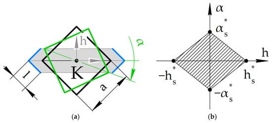
Figure 5.
A concept of grasping by diagonals: (a) a planar scheme for grasping a CubeSat 1U with design parameters; (b) grasping zone limits along linear and angular deviation axes.
Likewise in Equation (10), it holds .
The same method can be used to explain the linear and angular deviations for rectangular-shaped grasped bodies with sides equal to a and b, as shown in Figure 6a. The h-axis is placed perpendicularly to one of the diagonals of the grasped body. The diagonal d for the grasped body can be found via the Pythagorean theorem, as . Maximal linear deviation for the rectangular grasped body h*r in Figure 6b remains the same as in the previous case for a square-shaped body, i.e., . Angular deviation α*r can be presented as a ratio between the grasping zone width and the grasped body diagonal, as
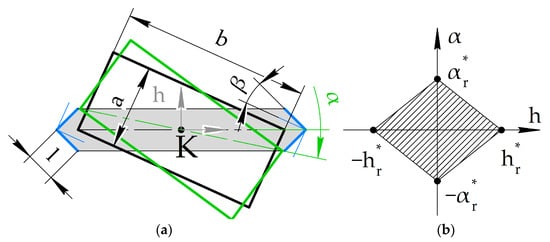
Figure 6.
A concept of grasping a rectangle-profiled body by diagonals: (a) a planar scheme for grasping a CubeSat 6U with design parameters; (b) grasping zone limits along linear and angular deviation axes.
For a square-shaped grasped body, diagonals are orthogonal to each other and at 45 degrees to both corresponding sides. Both fingertips are parallel to the sides of the grasped body, and the central line of the grasping zone is coplanar to the diagonal d of the grasped body. However, for the rectangular shaped body, as in Figure 6, the diagonal divides the right angle between its sides into two nonequal angles. To comply with this diagonal, the fingertips should be able to rotate at angle β. As mentioned above, the angle between a central line and each side of a fingertip is equal to 45 degrees. The angle γ between the diagonal of the rectangular grasped body and their sides a and b can be computed as the arctangent function between its sides, or . The angle β is a difference between 45 degrees and this function, as
CubeSats 1U–3U and 12U correspond to this last case of study. For grasping rectangular shaped CubeSats 6U, the fingertips should be adaptive and rotate by angle β. Using Equations (10)–(12), numerical results for linear h and angular α deviations can be computed as listed in Table 1 for the L-shaped fingertips with a side equal to 25 mm.

Table 1.
Maximum computed deviations for grasping CubeSats 1U, 6U, and 12U.
2.3. Gripper Kinematic Scheme
For the grasping configurations in Figure 5 and Figure 6, a novel gripper design is proposed to grasp different types of CubeSat from 1U to 12U. In previous works [25,26], the conceptual design has been presented as based on a double slider-crank mechanism, as shown in Figure 7 with the two configurations opened and closed. In the opened configurations, the distance between fingertips corners dmax is set to be 5% larger than the diagonal of the largest CubeSat 12U for a compact design, or 336.0 mm. For the closed configurations, the distance dmin is set 1% lower than the diagonal of the smallest CubeSat 1U, or 140.0 mm, to ensure grasping. In Figure 7, a general configuration of a mechanism is presented with the distance d/2 from the center of the mechanism to the one of the fingertips. For the gripper design, a distance p equal to 25 mm is set between the fingertip corner C1 or C2 and the crank end B1 and B2, respectively. In the opened configuration, the distance l0 is the lengths sum of two cranks OA1 and A1B1 for the first finger or OA2 and A2B2 for the second finger. In the closed position, the mechanism becomes the right triangle, where the crank A1B1 with the length l2 is the hypotenuse, and the crank OA1 is one of the catheti. The distance l0 becomes another cathetus of the right triangle in the closed configuration. Length l0 is equal to d/2 minus h, and it is known in opened and closed configurations of the gripper. Then lengths l1 and l2 of cranks can be found by solving the geometry of the mechanism configuration given by
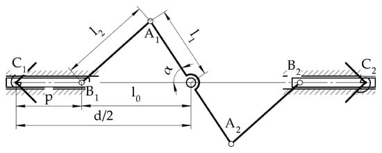
The length l1 calculated by Equation (13) is equal to 64.4 mm, and the length l2 is equal to 78.6 mm. These lengths are used as crank lengths in the CAD design of the gripper prototype.
The singularities of the slider-crank mechanism, corresponding to its fully extended or retracted configurations, are here avoided by operating the mechanism in its singularity-free range. This is physically ensured by dimensioning the slider to physically constrain its motion range.
2.4. Gripper CAD Design
The CAD design of the built prototype is presented in Figure 8a. A simplified gripper model from [26] has been redesigned for 3D printing and testing as a lab prototype, as shown in Figure 8b, with all the components that are manufactured in PLA. For the input actuation, a servomotor Dynamixel AX-12A [27] has been chosen. The model of this motor is covered by two parts, which protect the motor from external conditions and are used as basis for other parts. Two rails—180 mm long and 20 mm maximum width—are used for translational movement of the fingers. The rails have a trapezoidal profile and a place for ball bearings to keep the fingers. They are inserted into the pockets that are adjusted to the enclosures of the motor. The pockets are designed to fold the gripper rails and keep them unfolded when the gripper is in use. The fingers consist of three parts, such as the car, the fingertip, and the cap with flexible elements. The car is 40 mm long, its profile repeats the profile of the rail with the gap 0.2 mm, and it has sockets for six ball bearings from each side. It has a hole for the crank and a socket for the fingertip. This socket is designed with a restrictor that limits the free rotation of the fingertip by 21.16 degrees clockwise and counterclockwise. The L-shaped fingertips are designed on a cylindrical platform with a diameter of 20 mm. The 25 mm wide and 70 mm long sides of the fingertip are placed 90 degrees with respect to each other. The central crank is double the length l1, or 128.8 mm, and the lengths of two other cranks are equal to l2, or 78.6 mm.
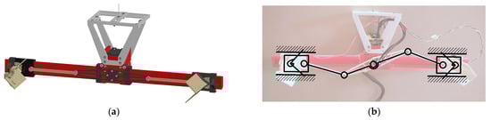
Figure 8.
A design of the proposed gripper from Figure 6: (a) CAD design; (b) a photo of the lab prototype with kinematics scheme and sensor setup.
For laboratory testing, an adjustable support has been designed. When sensors are installed on fingertips, the center of the mass can slightly move from the initial position. The platform allows the device to hang and manually center the gripper along two axes in 70 × 43 mm range.
2.5. Testing Design and Modes
The lab gripper prototype is made from the CAD model from Figure 7. The parts are printed in PLA material with 20% grid infill. The tolerances between the moving parts are 0.2 mm. Flexible elements are taken off to reduce resistance and friction for better adjustment of a fingertip during contact with the grasped body. The final mass of the printed prototype with the installed Arduino board is 215 grams.
In Figure 9, the grasped body is a cardboard box 210 mm × 210 mm × 50 mm, which is close to the dimensions of CubeSat 12U. The larger surface 210 mm × 210 mm is placed parallel to the gripper mechanism. The distance between the central gripper link and the surface of the gripped body is set to 40 mm. The mass of the box is 160 g.
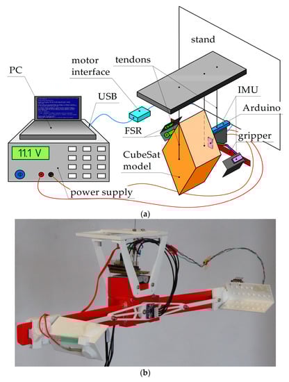
Figure 9.
A laboratory setup for gripper testing: (a) a scheme; (b) lab prototype with sensors.
The Dynamixel AX-12A motor of a gripper is powered by an external 11.1 V power supply and controlled by the U2D2 computer interface. The motor is controlled by the software Dynamixel Wizard 2.0. It allows the device to control the speed, torque, limit rotation angles, and obtain real-time data, such as current usage and present position. Grasping is performed by movements of the motor, which are manually controlled by the Dynamixel Wizard 2.0 software.
To measure impact during grasping operation, two inertial measurement unit (IMU) sensors BMI160 and two force sensor resistors FSR-400 are installed on the gripper. FSR-400 [28] can measure the forces from 0.2 N to 20 N with a sensing circular area of 5.6 mm diameter. BMI160 [29] is the inertial measurement unit sensor (IMU), consisting of a gyroscope and a 3-axis accelerometer. The gyroscope can measure up to 2000 deg/s, and the accelerometer range is up to 16 g. The sensor BMI160 is installed on the module GY-BMI160 to communicate with the Arduino board.
Two force sensors are positioned in one fingertip. The first force sensor is placed on the fingertip inner surface at 20 mm from the top of the fingertip and 10 mm from its long side. The second force sensor is placed on the inner surfaces of the fingertip on the same distance from its top. The central IMU sensor is placed on the center of the central frame link of the gripper driving mechanism. Another IMU is placed on the outer side of the fingertip at 8 mm from the bottom rib of the fingertip. The experimental set up is shown in Figure 8b and Figure 9a with the sensored prototype shown in Figure 9b.
Two force sensors are placed at the fingertip and measure the contact forces when grasping. One force sensor is set between the sides of the fingertip. The ribs of the carton box are with the 1 mm radius, and a small platform is designed to transmit contact forces from this rib to the sensor. Another fingertip is on one side of the fingertip; the coordinates of its center are 20 mm from its top and 15 mm from the edge. If the grasping is successful, the surface of the box touches it and a contact is registered. Another contact platform on the side of the fingertip is used to transmit distributed forces to the small surface of a force sensor.
Force sensor resistors, which are named FSR in Figure 9, are used to register the existence of a contact but not for the precise measurements. However, sensor calibration has been conducted using reference weights and the Arduino board. The datasheet [28] shows nonlinear resistance or conductance. The sensor was connected to an analog pin of Arduino with 10K Ohm resistor, and the data were acquired as a signal from 0 to 1023. The function of the form y = k1/(x + k2) + k3, where k1 = −1000, k2 = −1023, and k3 = −0.97 are the empirical coefficients, was applied to the acquired data to convert them into Newtons.
Arduino Nano Every is used to acquire the data from the IMU and force sensors. It is installed on the gripper below the support platform. I2C connection is used to acquire the data from the IMU sensors; three components of angular velocities and three components of linear acceleration are taken from each sensor. Two components of force data are taken from the force sensor resistors. The frequency of acquiring data for 14 components in total is 15 Hz, with the 115,200 baud rate set on the Arduino board.
The test is planned in grasping a CubeSat-like object of representative shape and size, holding it for a period of time, and releasing it. At the beginning, the gripper is opened at 160 degrees. To grasp the object, the gripper is closed at 138 degrees and keeps this position to hold it. The commands of grasping and releasing are given by a user using Dynamixel Wizard 2.0 software. The full operation time takes about 8.5 s, similar to a berthing operation with a CubeSat in space, and this time can be considered enough to observe the successful operation and behavior of the system, including gripper oscillations together with the grasped body.
3. Results
The acquired data from grasping test are shown in Figure 10, Figure 11 and Figure 12. In Figure 10 and Figure 11, IMU1 is the sensor installed on the central link of the gripper. The largest angular velocities of 45 deg/s are along rotation axis Z, and the values of angular velocities decrease when the gripper contacts with the grasped body. The IMU2 installed at the fingertip shows impact when grasping. The velocity components change direction in the moment of a contact.
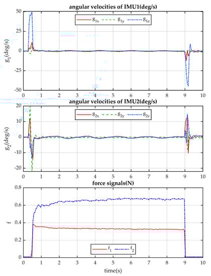
Figure 10.
Acquired data of angular velocities from IMU and the force data from the force sensors.
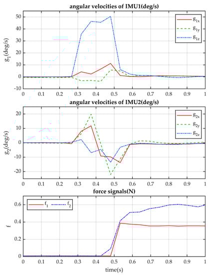
Figure 11.
Zoomed view of the data in Figure 10.
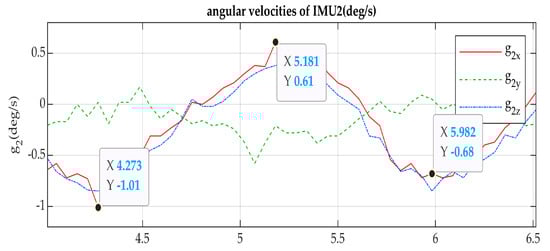
Figure 12.
Zoomed view of angular velocities of the second IMU in Figure 10.
The test concerns grasping a CubeSat-like object of representative shape and size, holding it for a period of time, and releasing it. At the beginning, the gripper is opened at 160 degrees. To grasp the object, the gripper is closed at 138 degrees and keeps this position to hold it. The commands of grasping and releasing are given by a user using Dynamixel Wizard 2.0 software. The full operation time takes about 8.5 s, similarly to a berthing operation with a CubeSat in space, and this time can be considered enough to observe the successful operation and behavior of the system, including gripper oscillations together with the grasped body.
Grasping acquired data f1 correspond to the force sensor set in the fingertip center. An increase in the force data values does not ensure proper contact with the rib of the grasped body. One of the explanations of this phenomena is the gravity affecting the fingertip action. It takes more time to adjust the fingertip properly, even if the input motion of the motor is stopped. Instead, the contact with the force sensor f2 on the fingertip surface shows planned behavior with higher values at the beginning and then a constant value when the grasped body is held.
The impact of a grasping operation makes the gripper oscillate together with a grasped body for a period of 1.7 s and an amplitude of 1.6 degrees along the x-axis, as shown in Figure 12.
Figure 13 shows the accelerations of the frame point O and fingertip point C of the gripper during the grasp which, although including earth gravity (as in the stationary values), well indicate the grasping action with impacts and the consequent adjustment motions of the grippers with the grasped object.
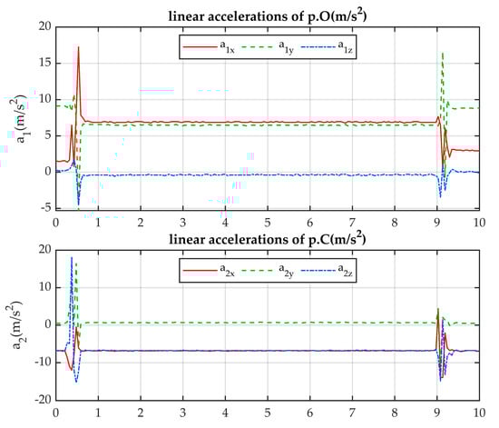
Figure 13.
Acquired data of linear accelerations of gripper points from IMU.
4. Conclusions
A low-cost lightweight design of a two-finger gripper prototype has been designed for a berthing operation with CubeSat satellites. A double-crank mechanism is used to grasp CubeSat bodies along diagonals from 140 to 330 mm with the maximal size 360 mm of a gripper. The folding scheme allows the device to reduce the dimensions of the gripper to keep it in a spacecraft launcher. A CAD design for a prototype is designed ready-to-print. A lab prototype is built for grasp testing. Acquired data from IMU and force sensors are used for evaluating and analyzing the main parameters of a grasping operation. The mechanism shows the successful grasping and holding of a body with CubeSat 12U dimensions with a calculated accuracy.
The reported test results numerically characterize the designed prototype, providing proof-of-concept for the proposed grasping berthing operation. In particular, the acquired angular velocities highlight a smooth motion and limited disturbance after the grasping operation and before release. The force values, although measured variations, suggest that the range that is required for the grasping operation is bound to an upper value lower than 0.7 N; this is thanks to the angular adaptability of the designed fingertips that provides a stable grasp by exploiting shape rather than relying on friction force only.
In addition, the test results from the IMU sensors indicate that they can be used to monitor and control the residual motion after operation, due to the overall inertia of the system in a low gravity setting. Further information can be extracted from the acceleration data, which show the initial impact of the fingertips on the grasped CubeSat satellite during the grasping phase and further (more limited) impacts and vibrations during the remainder of the grasping phase and release. In future developments, these data can be used for feedback, enabling closed-loop system control, or to improve the design by implementing an embodied damping system (e.g., with soft compliant interfaces).
Author Contributions
Conceptualization, M.C. and A.T.; methodology, A.T. and M.R.; formal analysis, A.T.; investigation, A.T., M.R. and M.C.; resources, M.C.; data curation, A.T. and M.R.; writing—original draft preparation, A.T. and M.C.; writing—review and editing, A.T., M.R. and M.C.; visualization, A.T.; supervision, M.C.; project administration, M.C.; funding acquisition, M.C. All authors have read and agreed to the published version of the manuscript.
Funding
This research received no external funding.
Data Availability Statement
No data other than those presented in the paper are available.
Conflicts of Interest
The authors declare no conflict of interest.
References
- Kessler, D.J.; Cour-Palais, B.G. Collision Frequency of Artificial Satellites: The Creation of a Debris Belt. J. Geophys. Res. 1978, 83, 2637–2646. [Google Scholar] [CrossRef]
- ESA Space Debris Office. ESA’s Annual Space Environment Report; ESA ESOC: Darmstadt, Germany, 2022; pp. 1–120. [Google Scholar]
- Liu, Y.; Zhao, Y.; Tan, C.; Liu, H.; Liu, Y. Economic Value Analysis of On-Orbit Servicing for Geosynchronous Communication Satellites. Acta Astronaut. 2021, 180, 176–188. [Google Scholar] [CrossRef]
- Laryssa, P.; Lindsay, E.; Layi, O.; Marius, O.; Nara, K.; Aris, L.; Ed, T. International Space Station Robotics: A Comparative Study of ERA, JEMRMS and MSS. In Proceedings of the 7th ESA Workshop on Advanced Space Technologies for Robotics and Automation, “ASTRA 2002”, Noordwijk, The Netherlands, 19–21 November 2002; pp. 1–8. [Google Scholar]
- Kuwao, F.; Otsuka, A.; Hayashi, M.; Aiko, Y.; Wakabayashi, Y.; Sato, N.; Doi, S. Operation Concept of JEMRMS. In Proceedings of the 7th International Symposium on Artificial Intelligence, Robotics and Automation in Space: I-SAIRAS 2003, Nara, Japan, 19–23 May 2003; pp. 19–23. [Google Scholar]
- Boumans, R.; Heemskerk, C. The European Robotic Arm for the International Space Station. Robot. Auton. Syst. 1998, 23, 17–27. [Google Scholar] [CrossRef]
- Oda, M. Summary of NASDA’s ETS-VII Robot Satellite Mission. J. Robot. Mechatron. 2000, 12, 417–424. [Google Scholar] [CrossRef]
- Hirzinger, G.; Landzettel, K.; Brunner, B.; Fischer, M.; Preusche, C.; Reintsema, D.; Albu-Schäffer, A.; Schreiber, G.; Steinmetz, B.-M. DLR’s Robotics Technologies for on-Orbit Servicing. Adv. Robot. 2004, 18, 139–174. [Google Scholar] [CrossRef]
- Mulder, T. Orbital Express Autonomous Rendezvous and Capture Flight Operations, Part 2 of 2: AR&C Exercise 4, 5, and End-Of-Life. In AIAA/AAS Astrodynamics Specialist Conference and Exhibit; American Institute of Aeronautics and Astronautics: Reston, VA, USA, 2008. [Google Scholar]
- Rupp, T.; Boge, T.; Kiehling, R.; Sellmaier, F. Flight dynamics challenges of the German on-orbit servicing mission DEOS. In Proceedings of the 21st International Symposium on Space Flight Dynamics, Toulouse, France, 28 September–2 October 2009. [Google Scholar]
- Moosavian, S.A.A.; Papadopoulos, E. On the Kinematics of Multiple Manipulator Space Free-Flyers and Their Computation. J. Robot. Syst. 1998, 15, 207–216. [Google Scholar] [CrossRef]
- Samani, F.; Ceccarelli, M. An Experimental Characterization of Torveastro, Cable-Driven Astronaut Robot. Robotics 2021, 10, 21. [Google Scholar] [CrossRef]
- Cafolla, D.; Araque-Isidro, J.E.; Ceccarelli, M. Design and Testing of Torveastro: An Outer Space Service Robot. Appl. Sci. 2023, 13, 1187. [Google Scholar] [CrossRef]
- Schmaus, P.; Leidner, D.; Krüger, T.; Schiele, A.; Pleintinger, B.; Bayer, R.; Lii, N.Y. Preliminary Insights From the METERON SUPVIS Justin Space-Robotics Experiment. IEEE Robot. Autom. Lett. 2018, 3, 3836–3843. [Google Scholar] [CrossRef]
- Diftler, M.A.; Mehling, J.S.; Abdallah, M.E.; Radford, N.A.; Bridgwater, L.B.; Sanders, A.M.; Askew, R.S.; Linn, D.M.; Yamokoski, J.D.; Permenter, F.A.; et al. Robonaut 2—The First Humanoid Robot in Space. In Proceedings of the 2011 IEEE International Conference on Robotics and Automation, Shanghai, China, 9–13 May 2011; pp. 2178–2183. [Google Scholar]
- Sofina, D. FEDOR: Meet Russia’s First Robot Astronaut (Who Also Does Splits). Available online: https://news.itmo.ru/en/science/cyberphysics/news/8710/ (accessed on 13 March 2023).
- Ceccarelli, M. Fundamentals of the Mechanics of Grasp. In Fundamentals of Mechanics of Robotic Manipulation; Ceccarelli, M., Ed.; International Series on Microprocessor-Based and Intelligent Systems Engineering; Springer Netherlands: Dordrecht, The Netherlands, 2004; pp. 241–304. ISBN 978-1-4020-2110-7. [Google Scholar]
- Monkman, G.J.; Hesse, S.; Steinmann, R.; Schunk, H. Robot Grippers; WILEY-VCH Verlag GmbH & Co. KGaA: Weinheim, Germany, 2007; ISBN 978-3-527-40619-7. [Google Scholar]
- Fei, F.; Yiwei, L.; Liu, H.; Hegao, C. Design Schemes and Comparison Research of the End-Effector of Large Space Manipulator. Chin. J. Mech. Eng. 2012, 25, 674–687. [Google Scholar]
- Bonivento, C.; Melchiorri, C.; Vassura, G.; Ferretti, G.; Maffezzoni, C.; Magnani, G.; Beccari, G.; Caselli, S.; Zanichelli, F. A Dexterous Gripper for Space Robotics. Artif. Intell. Robot. Autom. Space 1999, 440, 637–643. [Google Scholar]
- Johnstone, A. CubeSat Design Specification (1U-12U); CP-CDS-R14.1; Cal Poly SLO: San Luis Obispo, CA, USA, 2022; pp. 1–34. [Google Scholar]
- Fehse, W. Automated Rendezvous and Docking of Spacecraft; Cambridge University Press: New York, NY, USA, 2003; ISBN 978-0-521-82492-7. [Google Scholar]
- NASA; RSA; ESA; CSA. IDSS International Docking System Standard (IDSS) Interface Definition Document (IDD) Revision E; NASA: Washington, DC, USA, 2016; pp. 1–142.
- Nanosatellite & CubeSat Database. Available online: https://www.nanosats.eu/database (accessed on 14 February 2023).
- Titov, A.; Ceccarelli, M. Requirements and Problems for Space Berthing System. In Proceedings of the SYROM 2022 & ROBOTICS 2022; Springer International Publishing: Cham, Switzerland, 2023; Volume 127, pp. 127–135. [Google Scholar]
- Titov, A.; Ceccarelli, M. Design and Performance Characterization of a Gripper End-Effector for a Space Berthing Manipulator. In New Advances in Mechanisms, Transmissions and Applications; Springer Nature: Berlin/Heidelberg, Germany, 2023; Volume 124, pp. 15–22. [Google Scholar]
- ROBOTIS. E-Manual AX-12+, AX-12A. Available online: https://emanual.robotis.com/docs/en/dxl/ax/ax-12a/ (accessed on 27 April 2023).
- INTERLINK Eletronics. FSR® 400 Series Data Sheet. Available online: https://www.digikey.com/htmldatasheets/production/1184367/0/0/1/34-00022.pdf (accessed on 12 June 2023).
- Bosch Sensortec, BMI160—Data Sheet 2020. Available online: https://www.adeept.com/bmi160_p0137.html (accessed on 12 June 2023).
Disclaimer/Publisher’s Note: The statements, opinions and data contained in all publications are solely those of the individual author(s) and contributor(s) and not of MDPI and/or the editor(s). MDPI and/or the editor(s) disclaim responsibility for any injury to people or property resulting from any ideas, methods, instructions or products referred to in the content. |
© 2023 by the authors. Licensee MDPI, Basel, Switzerland. This article is an open access article distributed under the terms and conditions of the Creative Commons Attribution (CC BY) license (https://creativecommons.org/licenses/by/4.0/).