Abstract
A positioning system employing visual fiducial markers (AprilTags) has been implemented for use with handheld mine detection equipment. To be suitable for a battery-powered real-time application, the system has been designed to operate at low power (<100 mW) and frame rates between 30 and 50 fps. The system has been integrated into an experimental dual-mode detector system. Position-indexed metal detector and ground-penetrating radar data from laboratory and field trials are presented. The accuracy and precision of the vision-based system are found to be 1.2 cm and 0.5 cm, respectively.
1. Introduction
1.1. Application Background
Landmines and explosive remnants of war (ERW) remain a significant global issue. According to recent data [] at least 5757 people in 53 states and other areas were killed or injured by landmines globally in 2023/24. As of October 2024, 58 states and areas are reported or suspected to be contaminated with anti-personnel (AP) landmines. Seven parties to the Mine Ban Treaty have reported “massive” AP landmine contamination (that is, areas over 100 ); however in many cases the full extent of the contamination is unclear. For example, according to [], reports on the number and size of mined areas within Ethiopia have been “plagued with inconsistencies” and until comprehensive surveys are undertaken, the situation will remain challenging. Similarly, according to the Halo Trust [], it can only be “broadly estimated” that some two million landmines have been laid in Ukraine since the start of the conflict. The true level of contamination is difficult to determine due to ongoing hostilities.
Civilians are disproportionately affected by landmines, making up 84% of victims in 2023 [], with children making up 37% of civilian casualties. Furthermore, the legacy of mine contamination renders large areas of land unavailable for agricultural, domestic, or industrial use until the mines can be removed. Therefore, any new technologies that can aid in the surveying and clearance of contaminated land are both timely and essential for effectively regaining land use post-conflict.
Manual demining remains an important part of the clearance process. The process of manual demining involves the location and detection of potential targets for subsequent excavation and removal. The methods employed for demining are carried out in accordance with standard operating procedures (typically aligned with guidance from the United Nations []). Manual clearance typically involves the deminer using search patterns from a defined safe baseline. When the detector alarms, the deminer needs to mentally note the position on the ground, move the search head away, and approach the target from multiple directions. Normal operating procedures frequently require a zigzag or raster search pattern around the alarm region to localise the target, particularly in the case of dual-mode metal detector and ground-penetrating radar (GPR) systems. This process is repeated several times until the deminer develops a picture of the area before laying a marker on the ground above where they believe the target is. Accurate placement of the marker (to within a few centimetres) is an essential prerequisite for efficient target excavation and removal.
A real-time positioning system applied to a handheld landmine detector could significantly aid the demining process. Existing handheld demining systems only return a time series of the detector response, making subsequent analysis difficult and indexing the response back to the ground impossible. Inclusion of a positioning technology within a handheld detector system would allow construction of a map of the detector response over the scanned area, potentially providing a reference for more accurate placement of signal markers. Additionally, the map could indicate the progress of the scan and indicate any areas yet to be scanned before moving to a new search area, thus improving scan quality. One key advantage of position-indexed measurement data is that it provides a more quantitative description of the detected target size and shape compared with the conventional mental picture developed by the deminer.
Positioning data allows multiple measurements over the same target to be combined, which can enhance the system’s signal-to-noise ratio. One of the overarching aims of this project was to combine positioning data with advances in magnetic polarisation tensor (MPT) measurement for metal detector data [] and, combined with GPR data, to allow the development of a system capable of identifying and classifying the target before being excavated []. Recent work in this area has used position tracking information linked with machine learning for better characterisation of the metal target [,].
There are additional significant non-technical benefits to enhancing demining processes with position data. The foremost among these is increased quality control over the demining process. Position data allows the progress of demining to be monitored and evaluated. Tracking the pose of the detector head can provide increased feedback to the operator and field supervisors, ensuring that critical factors such as lift-off and head orientation are maintained within operational limits to ensure that optimal detector performance is maintained. Furthermore, this data can be used to trend operator performance over time to indicate signs of fatigue or the need for additional training. Recording of data indexed with position provides increased traceability of demining processes, which can then be used for historic trending and subsequent analysis. This allows demining teams to make operational efficiency improvements based on first-hand field data.
The contributions of this paper are as follows:
- Demonstration of a low-power, high-frame-rate positioning system applicable to handheld demining equipment;
- Empirical evaluation of this system to assess its accuracy and precision for its intended purpose;
- Integration of this system within the experimental demining hardware;
- An understanding of how the positioning sensor precision is influenced by tag size, as this is an important practical consideration for deminers in the field.
1.2. Alternative Approaches to Positioning
Several technologies exist for providing positional information for indoor and outdoor applications. In their paper describing electromagnetic tracking of pulse induction search coils, Ambrus et al. give a comprehensive review of tracking technologies considered for application to handheld detectors used in humanitarian demining ([] and references therein). Such systems include optical/vision-based systems, ultrasonic triangulation, inertial sensors, ultrawideband localisation, and standalone accelerometers. The authors of [] opt for a system based on tracking the magnetic field generated by the head.
For outdoor environments, satellite navigation-based methodologies such as D-GPS and RKT-GPS can offer centimetre-level positional accuracy and precision compared with conventional GPS []. Although GPS has worldwide coverage, limitations can exist in urban situations or locations where line-of-site obstructions exist. Additionally, systems such as D-GPS and RKT-GPS can be prohibitively expensive and typically involve time-consuming local beacon setup. For indoor environments, a commonly used technology for real-time localisation uses visual fiducial markers. This offers the advantage of straightforward setup and relatively low cost. This type of technology is routinely used in robotics applications, augmented reality, and vision-based tracking systems []. AprilTag is one type of commonly used visual fiducial marker system [,]. Vision-based tracking systems can broadly be categorised into those that use features already existing in the scene (either natural or man-made) and those using fiducial markers artificially introduced into the scene for the purpose of tracking. These classes can be further divided based on whether the application is indoors or outdoors and again based on the range and accuracy of the system. Early application of computer vision-based positioning to landmine clearance using a handheld detector was described in the work of Beumier et al. [,]. In their work, a monocular camera was rigidly attached to a detector head and, following feature extraction from 1-Megapixel frames, the pixel coordinates of points at known positions on a marked bar were used to calculate the detector head position in the frame of the bar with centimetre accuracy and precision at a frame rate of 10 Hz [].
1.3. Overview and Structure
In this paper, we analyse the accuracy and precision of an AprilTag-based system integrated into a handheld detector system. The primary performance requirement for this system is a high precision. While accuracy is important, systematic offsets can be corrected during post-processing once the system is calibrated. A high precision ensures consistent and repeatable measurements, which are necessary for reliable data interpretation and trending over time.
Since landmines can be found in environments as diverse as desert and heavy rainforest, there is the potential for both a great variety or near total absence of features within the terrain in which the system is expected to operate. Therefore, this research has opted to employ fiducial markers (AprilTags) as opposed to natural features. The proposed operating method is that a marker will be placed by the system operator in a safe area near the region to be scanned.
This paper is structured as follows: Section 2 gives a description of the system and provides background on the use of AprilTags; Section 3 details how the pose of the detector head is determined in the frame of reference of the position tag; Section 4 describes the implementation of this algorithm in software and its implementation within the experimental detector system; Section 5 describes the methods for laboratory evaluation of the positioning system; Section 6 presents and discusses the results of these tests; and Section 7 gives conclusions and the outline for future work.
2. The Dual-Mode Detector System
2.1. System Description
The vision system presented in this paper has been implemented into a bespoke dual-modality handheld landmine metal detection system developed by the University of Manchester (Figure 1) and supported by the Sir Bobby Charlton Foundation [].
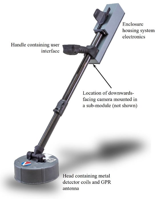
Figure 1.
The University of Manchester experimental detector system.
The detector integrates spectroscopic metal detection (MD) with GPR to discriminate between threat targets and benign clutter items []. The detector uses a sensing head measuring approximately 0.25 m in diameter and has an overall length from the base of the detector head to the arm bracket of 1.2 m. The camera of the vision system is located on the lower part of the control box housing the control and data acquisition electronics of the detector. The arrangement gives a rigid and robust fixed position of the camera with respect to the detector head. The handheld, battery-powered nature of this detector drives the performance requirements of the positioning system. The functional requirements of the position system are low power consumption (approximately 100 mW), low mass (less than 100 g), compact size, and a frame rate greater than 30 fps. The power requirement ensures that the detector can operate for an approximately 8 h demining shift on a single battery charge. The frame rate ensures that the system can capture the position at a sufficient spatial resolution to keep up with normal demining scan patterns and speeds. Comparable systems such as HSTAMIDS, VMR1 Minehound, and ALIS have suggested sweep speeds between 30 cm/s and 1.5 m/s []. With a frame rate of 50 Hz, this equates to a best-case spatial resolution of between 6 and 30 mm. However, the positioning precision and synchronisation between the positioning and detector subsystems will necessarily limit the system resolution to less than that given by the frame rate.
The combination of these requirements necessarily limits the accuracy and precision of the system, which both had a design target of ≈1 cm. Using the full capabilities of the OpenMV software (Section 4) with additional off-chip RAM would allow the system to operate at full VGA resolution, which would likely afford a higher precision and potential accuracy at the cost of a lower frame rate and increased power consumption.
A 3.3 mm focal length, low-distortion (<1%) M12 mount lens, with a fixed aperture of f/2.8, was chosen for this application. Combined with the MT9V034 image sensor, this lens gave the system a field of view on the ground of approximately 100 cm by 70 cm with the stem at maximum extension, which is sufficient to capture a nominal demining strip.
2.2. AprilTag Visual Fiducials
Visual fiducials serve as artificial landmarks that can be used for localisation problems. Individual markers can be easily distinguished from one another and convey information in manner similar to other planar 2D barcode systems such as QR codes []. For localisation problems, such systems need to provide translation and rotation information when viewed from a given perspective, i.e., six degrees of freedom (DOF). The AprilTag system [,] developed at the University of Michigan is a freely available library implemented in C, which can be hosted on embedded devices and allows for full 6-DOF localisation from a single image. AprilTags typically encode up to 12 bits of data to provide the 3D position with respect to the viewing camera and consist of mosaic patterns. An example AprilTag marker and the simplified steps used in determining the pose of the tag with respect to the camera frame of reference are shown in Figure 2. In this work, AprilTags generated from the Tag36h11 family are used to estimate the position of the sensing head of a handheld landmine detector with respect to a tag placed in a safe location on the ground.
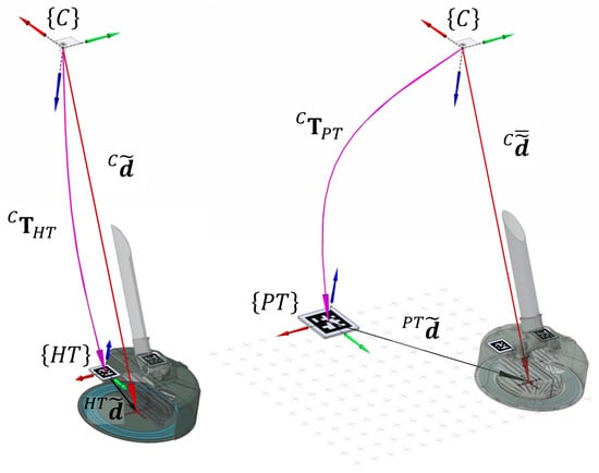
Figure 2.
Illustration of the pose calculation relating the camera, head tag, and position tag frames of reference. The labelling and nomenclature are detailed in full in Section 3.
The deminer places a single cm AprilTag on the ground close to where a detector alarm has been triggered. This single tag is referred to as the position tag, PT. The detector head has two cm AprilTags mounted on the upper surface, which are referred to as head tags, HT. The positioning system camera (C) is contained within the electronics housing and mounted on the stem beneath the operator’s hand, pointing toward the ground. The AprilTag algorithm ([,] and Section 4) is used to locate both the position and head tags in frames from the camera. In this work, braces around a symbol () are used to donate the frame of reference with respect to the object A. A tilde over a position vector denotes homogeneous coordinates.
3. Determination of Detector Head Position
Having located a tag in a frame from the camera, the AprilTag algorithm returns an estimate of the pose of that tag with respect to the camera as a transformation matrix from the frame of the tag T to the frame of the camera C []. In the absence of a “world” coordinate frame, we require the detector head position in the frame of reference defined by the position tag, . Homogeneous coordinates are used for position vectors to allow for mapping between coordinate frames using transformation matrices , composed of a rotation matrix and a translation vector :
Prior to a scan, repeated estimates of the pose of the head tags allow a measurement of the position of the centre of the detector head in the frame of the camera . During the scan, this measurement of is used with real-time estimates of the pose of the position tag to derive .
3.1. Measurement of Detector Head Position in the Frame of the Camera
Two tags from the AprilTag family 25h9 are attached at known positions on the detector head, as can be seen in Figure 2. Following any adjustment of detector stem length and head angle, the AprilTag algorithm locates the head tags in n successive frames, and estimates of the pose derived from these frames are used to give the position of the centre of the detector head in the frame of the camera . In the frame of each of the head tags , the location of the centre of the head is known. Therefore, is given by
is calculated in this way for a sequence of n frames to give an average measurement .
3.2. Measurement of Detector Head Position in the Frame of the Position Tag
The single position tag (), placed on the ground by the deminer in the proximity of a detector alarm, is from the AprilTag family 36h11. The field of view of the camera is such that this tag must remain within the frame and be located by the AprilTag algorithm while the detector is scanned in proximity to the alarm. The estimated pose of the position tag relative to the camera , returned by the AprilTag algorithm, is used to calculate the position of the detector head centre in the frame of the position tag . The position of the centre of the detector in the frame of the camera () is fixed during a scan and can be estimated a priori (as described above). It is related to and via
Figure 2 also gives a schematic illustration of Equation (2). Rearranging this for gives
which can be expanded [] via
where is the transpose of the rotation matrix describing the rotation between the frame of the camera C and the frame of the position tag . is the translation vector from the frame of the camera to the frame of the position tag. As discussed, is the detector position in the frame of the position tag , as required.
4. Software Implementation of AprilTags Within the Detector
The OpenMV project [] developed an open-source, low-cost machine vision platform based around an STM32 ARM processor and MT9V034 image sensor, running an implementation of MicroPython. The position system developed in this work is based on the OpenMV H7 system and is integrated into an extension module beneath the electronics housing.
Once the sensor is initialised, a class to locate the head tags (in the frame of the camera) is instantiated. The key variables for this class are as follows:
- The coordinates of the detector head centre in the frame of each of the two head tags. These are fixed by the geometry of the head and the size of the tags and remain fixed between systems of the same design.
- The number of measurements of the head tags to collect and average over. In field trials, 15 measurements have been used.
- This class captures a frame, attempts to find both head tags within it, and checks to ensure these are of the required type. If both tags found are of the required type, then the position of each within the frame of the camera is measured. Once the required number of measurements is obtained, these are averaged and the result can be used in subsequent calculations. A second class handles the tracking of the position tag, which is the reference point for head position measurement. This class repeatedly grabs images from the camera sensor and applies the find_apriltags algorithm [] on subsequent frames. A region of interest and sensor window can be defined to ensure that the system remains within the limited memory bounds. This is difficult to precompute, as the number of potential features within an individual frame (and that may be found by the algorithm) depends on the background.
The camera was calibrated offline on a PC using the camera calibration routine within OpenCV. This process captures images of an asymmetric target grid of circles at a range of target positions and stem angles. This process determines the focal length and camera centre parameters, which are then fixed throughout the remainder of the tests.
5. Methods Used to Validate the Vision Positioning System
Two methods were used to validate the performance of the positioning system: a static method and dynamic method.
5.1. Static Validation Method
A static evaluation of the accuracy and precision of the vision positioning system was carried out using a printed array of thirty-four unique AprilTags from the family 36h11. These were arranged on a grid, as shown in Figure 3. The tags in the printed validation array are 10 cm squares, including a white border, like those used in the final system. The centre points of the tags in the array are spaced by 10 cm in the x and y directions such that there is no space between them; the 1 cm wide white borders are part of the tags themselves [].
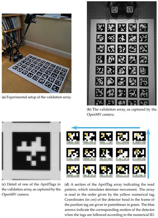
Figure 3.
Details of the AprilTag array used in validating the position system.
The array was locked in position relative to the detector and vision system by mounting all components to a common baseboard (Figure 3a). For the static evaluation, the vision system was mounted on a GRP tube with a dummy detector head mounted on the board. The head tags of the dummy head were located at the same position relative to the detector centre as in the detector head. In Figure 3b an image of the static validation array is captured using the vision system camera. The two head tags from the family 25h9 can be seen on the dummy detector head at the top of Figure 3b, along with plates locking the head to the array. With this arrangement, the detector head centre was locked in position relative to the array of tags.
A Python script was written to control the vision system for the static tests. Each tag in the array was selected via its numerical ID and 300 camera frames were captured for each, allowing repeat measurements of the position of the centre of the detector head relative to that tag. Reading from left to right across the array corresponds to motion of the detector head in the opposite direction, such that the x coordinate of the detector head changes from 20 to −20 cm moving left to the right across the sheet (Figure 3). Similarly, moving down the sheet (from the point of attachment at the top of the array) corresponds to motion of the detector away from the tag in the positive y direction such that the y coordinate of the detector head position increases down the sheet. The field of view of the lens used on the vision system is such that the row of tags at the bottom of the image corresponds to a y displacement of the detector head centre of 77.3 cm. This is larger than the typical movement of the sensor head, as that motion is limited by demining strips, which measure approximately 60 cm in this dimension.
In the results shown in this work, the stem was extended to its maximum extent and the stem angle was set at using a digital angle gauge. Set up in this way, the camera-to-pivot distance was approximately 78 cm and the camera was at a height of 77 cm above the tag array, with the base of the dummy detector raised 0.95 cm above the array of tags.
The results presented here were recorded indoors under natural light. The only light source was through windows; no other internal lighting was employed. With the room lights on, shadows interfered with the detection of the head tags. The results in this work were recorded in April/May 2021. The incident light level was recorded using a Sekonic L-608 light meter and measured at or above 5100 lux.
5.2. Dynamic Validation Method
To assess the performance of the positioning system under a more representative scenario, a dynamic test was also carried out. The position tag was located on a fibreboard “sled” and moved by an operator at approximately constant speed back and forth (along the x-axis) in front of the head, which was mounted in the fixed rig used in the static test. The stem angle was fixed at throughout. This method allows for continuous and dense sampling compared to the relatively discrete and sparse sampling allowed by a fixed array. This setup is shown in Figure 4.
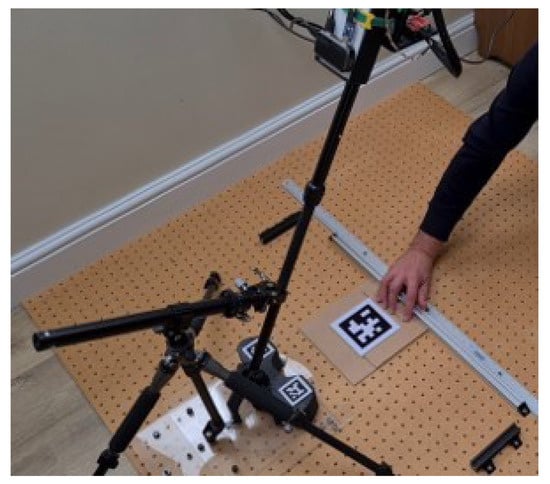
Figure 4.
The setup used in the dynamic validation of the positioning system. The tag is manually moved by the operator along the fixed bar shown at approximately constant speed.
Throughout this process the position was acquired by the vision system and recorded. This method was repeated for tags of three different sizes, 10.5 cm (as used in the static test), 13.1 cm, and 15.8 cm, in order to assess the effects of tag size on precision.
6. Results and Discussion
6.1. Results
Static validation results illustrating deviation from ground truth in the x and y directions ( and ) for the 300 frames captured for each tag in the validation array (pictured in Figure 3a) are shown in Figure 5. Above each plot the true detector position is given in parentheses and the numerical identifier in blue. The red line marked on this figure denotes the maximum y translation required from the system when working with a clearance strip 60 cm wide.
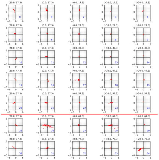
Figure 5.
Each plot contains the 300 measured points indicating the deviation from the true position (, ), as measured by the position sensor for each of the tags in the validation array. The red line indicates the maximum y position required for a demining lane 60 cm wide. The numbers in brackets indicate the true position of the tag. The axes of all graphs are in cm. These AprilTags correspond to those shown in Figure 3a.
The precision of the system is estimated by calculating the magnitude of the residual vector (as in Figure 5) for each recorded sample and calculating the standard deviation of this data.
The standard deviation for each tag is shown in Figure 6, in which the diameter of the circle is proportional to the standard deviation.
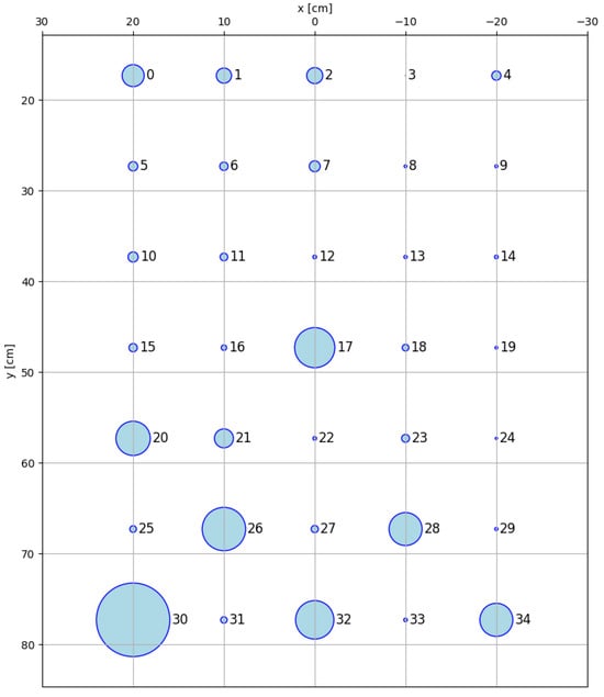
Figure 6.
The standard deviation of the measured tag position (radial component) with respect to the true position of the tag. The diameter of the circles is 3× the standard deviation. Tag numbers are given to the right of each circle.
As can be seen from Figure 5 and Figure 6, the precision of the positioning system varies across the tag array, with the lowest spread in position measurement (in the plane) found closest to the centre of the field of view of the lens (Tags 7, 8, 12 and 13). This increases towards the edges of the frame in both the x and y directions. The mean precision for this system across all tags was found to be 0.5 cm. When averaged across the tags above the red line (the approximate width of a demining strip), the precision improved to 0.4 cm.
The results of the dynamic testing are shown in Figure 7. To estimate the precision, a linear fit was made to the data for each tag and the root mean squared of the average residual was taken over all points measured.
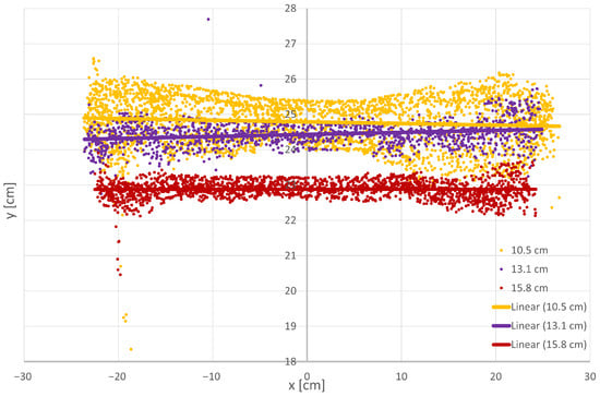
Figure 7.
Results of the dynamic validation tests. The estimated position is shown as points together with a linear fit to the data.
The estimated precision for each of the tests (static and dynamic) is summarised in Table 1. Each test shows that the system has a precision better than the target of 1 cm. The static test also allows an estimate of the accuracy. This was found to be 1.2 cm, which improves to 1.0 cm when only the tags within the nominal 60 cm demining strip are considered. An estimate of accuracy is not available from the dynamic test data.

Table 1.
Estimated precision in head position for the static and dynamic tests.
6.2. Discussion
Figure 5 and Figure 6 illustrate the static measurement of the system’s precision and how it varies with the true position of the target. It can be observed that there is a spread in precision across the AprilTag array, with the general trend that greater precision is achieved when the AprilTag is closer to the centre of the field of view of the camera.
Examination of the detailed scatter plots in Figure 5 suggests a possible mechanism that contributes to the spread in position measurements. It is known that when solving the pose estimation problem using four or more coplanar points on a fiducial marker, the problem of pose ambiguity occurs, as multiple pose solutions exist when using only a single marker image [,], which may be contributing to the spread seen here.
In addition to the pose ambiguity, degradation in precision can also arise due to sampling jitter in the extraction of the tag corner points [] from which the pose is calculated. When these points are used to compute the pose, this will lead to noise in the position vector and the rotation component. Within the default AprilTag implementation, a Gaussian blur is applied during processing to help reduce this sampling jitter. However, in the OpenMV implementation used in this work, hardware constraints mean that such processing would reduce the frame rate to an unacceptable level. In future work manual defocusing of the camera could be investigated to produce a similar effect. Furthermore, the static validation array has only a sparse sampling of points within the measurement space, which leads to apparently inconsistent results with respect to precision. This should be contrasted with the results from the dynamic tests, where the spatial sampling is significantly denser and shows a much more consistent trend across the field of view.
The scatter plots from the dynamic tests (Figure 7) all have a distinct “dumbbell” shape. The further the tag moves from the optical axis of the sensor (or vice versa) the larger the lever arm between the tag and sensor becomes. Any noise in the calculated pose resulting from errors in the rotation becomes amplified as a result and tends to introduce more scatter into the results.
During more realistic deployments of the system, further sources of error are likely to be introduced. When the system is used by a human operator, variation in the orientation and vertical displacement of the sensor will become important. During the experiments reported in this work, these parameters were kept under tight control, as both the sensor head and AprilTag were confined to a parallel and fixed configuration. Further work will be necessary to estimate the effect of variations in head vertical displacement and orientation on the precision and accuracy of the system.
The static and dynamic tests carried out demonstrate that the vision-based positioning system developed in this work meets the design target of <1 cm precision and is very close to the target of 1 cm accuracy (and meets the target when tags are restricted to the nominal 60 cm wide demining strip). In fact, it has been possible to achieve a sub-centimetre-level precision in both static and dynamic tests, which indicates that this method could form a viable part of a future demining system.
Currently, no attempt has been made to filter or smooth the position data. This would be expected to help reduce the overall noise in the system and should increase precision further.
Figure 8 shows the position system hardware integrated into the detector. Position data is streamed to the single-board computer controlling the detector and is used to index data from the metal detector and GPR subsystems.
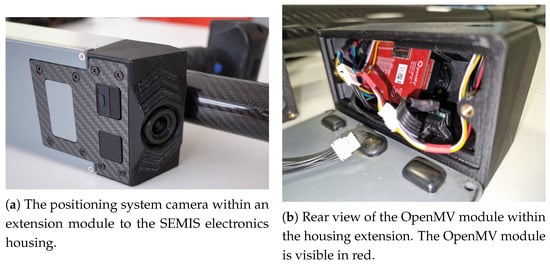
Figure 8.
Hardware integration of positioning system camera into the prototype detector system.
Figure 9 and Figure 10 are illustrative examples of metal detector and GPR data augmented with position information. Data is synchronised between MD, GPR, and position based on their recorded timestamp. This data was collected during field trials in 2022 at the Benkovac test site in Croatia. Full C-scan information can now be utilised to aid visual detection of the target and algorithms are under development to automate this.
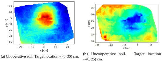
Figure 9.
Position-indexed metal detector data for a PMA2 surrogate buried at 10 cm depth. The colour scale is arbitrarily autoscaled within each image.
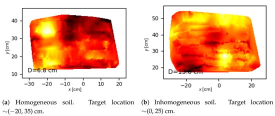
Figure 10.
Position-indexed GPR data for a PMA3 surrogate buried at 5 cm depth. The colour scale is arbitrarily autoscaled within each image.
Proposed visualisation techniques of position-enhanced detection data are shown in Figure 11, which can be visualised (in real time and off-line) using either a tablet computer or Microsoft HoloLens [] augmented reality device.
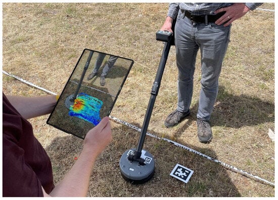
Figure 11.
Field trial of augmented landmine detection data.
7. Conclusions
A position system for a handheld landmine detector has been developed and integrated into an experimental detector system. A precision of <1 cm was specified and the system has been demonstrated to operate better than this; accuracy was not specified but is close to 1 cm and sufficient for the purposes in this work. Further work is ongoing to further improve both precision and accuracy and to assess the behaviour of the system under more representative conditions, as outdoor lighting and non-flat surfaces are likely to affect performance, particularly with regard to changes in the vertical displacement of the sensor and its orientation with respect to the AprilTag. As specified, the system operates on a limited power budget suitable for battery operation (≈100 mW) and at a frame rate viable for real-time applications (between 30 and 50 fps). Further work also is required to understand the impact of detailed interactions between the finite system precision, any averaging/filtering in the position, and the detector subsystem synchronisation on the final spatial resolution. Filtering or averaging position data would likely increase system precision, but this would be at a cost of a decreased system update rate, so further study is needed to understand the net benefits of this.
Position-indexed metal detector and GPR data from the prototype detector has been live-streamed to external hardware for display, evaluation, and post-processing. Work is ongoing to develop detection algorithms that can utilise this additional data source to improve the system’s signal-to-noise ratio and reduce the rate of false positive indications. Visualisation of position-indexed detection data highlights the utility of this data. Indexing detector data with position information can deliver many benefits to the demining process, such as increased operator feedback; real-time quality control; historic traceability of detector response; and data and operator performance trending.
Author Contributions
Conceptualisation, A.D.F., E.C., J.D., D.C., F.P., and A.J.P.; methodology, A.D.F., E.C., and J.D.; software, E.C.; validation, A.D.F., E.C., and J.D.; formal analysis, A.D.F., E.C., and J.D.; investigation, A.D.F., E.C., and J.D.; resources, A.D.F. and E.C.; data curation, A.D.F. and E.C.; writing—original draft preparation, A.D.F.; writing—review and editing, A.D.F., E.C., J.D., D.C., F.P., and A.J.P.; visualisation, A.D.F. and E.C.; supervision, A.J.P.; project administration, A.J.P.; funding acquisition, A.J.P. All authors have read and agreed to the published version of the manuscript.
Funding
This work was conducted as part of the programme SEMIS (Scanning Electromagnetic Mine Inspection System) with funding from the charity “Sir Bobby Charlton Foundation”.
Data Availability Statement
The data supporting this paper is available at https://doi.org/10.48420/30030226.v1 in a publicly available repository under licence CC BY-NC 4.0.
Acknowledgments
The authors would also like to thank Mr and Mrs Persey of Honiton, Devon, UK, for use of their grounds and hospitality during prototype testing. The authors would also like to thank Kwabena Agyeman of the OpenMV project for support in adapting the OpenMV source code to suit the requirements of this project. The authors have reviewed and edited the output and take full responsibility for the content of this publication.
Conflicts of Interest
The authors declare no conflicts of interest. The funders had no role in the design of the study; in the collection, analyses, or interpretation of data; in the writing of the manuscript; or in the decision to publish the results.
References
- ICBL-CMC. Landmine Monitor 2024, 26th ed.; International Campaign to Ban Landmines: Geneva, Switzerland, 2024. [Google Scholar]
- Landmine and Cluster Munition Monitor. Mine Action: Ethiopia. Available online: https://archives2.the-monitor.org/en-gb/reports/2022/ethiopia/mine-action.aspx (accessed on 28 July 2025).
- HALO Trust. Ukraine: Surveying and Clearing Mines. Available online: https://www.halotrust.org/where-we-work/europe-and-caucasus/ukraine/ (accessed on 28 July 2025).
- Office of Military Affairs, Department of Peace Operations, United Nations. Military Explosive Ordinance Disposal Unit Manual; Office of Military Affairs, Department of Peace Operations, United Nations: New York, NY, USA, 2021. [Google Scholar]
- Marsh, L.A.; van Verre, W.; Davidson, J.L.; Gao, X.; Podd, F.J.W.; Daniels, D.J.; Peyton, A.J. Combining Electromagnetic Spectroscopy and Ground-Penetrating Radar for the Detection of Anti-Personnel Landmines. Sensors 2019, 19, 3390. [Google Scholar] [CrossRef]
- Šimić, M.; Ambruš, D.; Bilas, V. Inversion-Based Magnetic Polarizability Tensor Measurement From Time-Domain EMI Data. IEEE Trans. Instrum. Meas. 2023, 72, 1–11. [Google Scholar] [CrossRef]
- Šimić, M.; Ambruš, D.; Bilas, V. Machine Learning Assisted Characterization of Hidden Metallic Objects. IEEE Sens. Lett. 2025, 9, 1–4. [Google Scholar] [CrossRef]
- Šimić, M.; Ambruš, D.; Bilas, V. Landmine Identification From Pulse Induction Metal Detector Data Using Machine Learning. IEEE Sens. Lett. 2023, 7, 1–4. [Google Scholar] [CrossRef]
- Ambruš, D.; Šimić, M.; Vasić, D.; Bilas, V. Close-Range Electromagnetic Tracking of Pulse Induction Search Coils for Subsurface Sensing. IEEE Trans. Instrum. Meas. 2021, 70, 1–13. [Google Scholar] [CrossRef]
- Pirti, A. Performance Analysis of the Real Time Kinematic GPS (RTK GPS) Technique in a Highway Project (Stake-Out). Surv. Rev. 2007, 39, 43–53. [Google Scholar] [CrossRef]
- Rambach, J.; Pagani, A.; Stricker, D. Principles of Object Tracking and Mapping. In Springer Handbook of Augmented Reality; Springer International Publishing: Cham, Switzerland, 2023; pp. 53–84. [Google Scholar] [CrossRef]
- Olson, E. AprilTag: A robust and flexible visual fiducial system. In Proceedings of the 2011 IEEE International Conference on Robotics and Automation, Shanghai, China, 9–13 May 2011; pp. 3400–3407. [Google Scholar] [CrossRef]
- Wang, J.; Olson, E. AprilTag 2: Efficient and robust fiducial detection. In Proceedings of the IEEE/RSJ International Conference on Intelligent Robots and Systems (IROS), Daejeon, Republic of Korea, 9–14 October 2016. [Google Scholar]
- Beumier, C.; Yvinec, Y. Positioning System for a Hand-Held Mine Detector. In Mine Action; Beumier, C., Closson, D., Lacroix, V., Milisavljevic, N., Yvinec, Y., Eds.; IntechOpen: Rijeka, Croatia, 2017; Chapter 2. [Google Scholar] [CrossRef]
- Beumier, C.; Druyts, P.; Yvinec, Y.; Acheroy, M. Motion estimation of a hand-held mine detector. In Proceedings of the 2nd IEEE Benelux Signal Processing Symposium, Hilvarenbeek, The Netherlands, 23–24 March 2000. [Google Scholar]
- Sir Bobby Charlton Foundation. SBCF. Available online: https://www.thesbcfoundation.org/ (accessed on 7 August 2023).
- Guidebook on Detection Technologies and Systems for Humanitarian Deming; International Centre for Humanitarian Demining: Geneva, Switzerland, 2006.
- Chu, C.H.; Yang, D.N.; Chen, M.S. Image stablization for 2D barcode in handheld devices. In Proceedings of the 15th ACM International Conference on Multimedia, Augsburg, Germany, 25–29 September 2007; pp. 697–706. [Google Scholar] [CrossRef]
- Corke, P. Robotics, Vision and Control: Fundamental Algorithms in MATLAB, 3rd ed.; Springer Tracts in Advanced Robotics; Springer: Cham, Switzerland, 2023. [Google Scholar]
- OpenMV. OpenMV: Machine Vision with Python. Available online: https://openmv.io/ (accessed on 7 August 2023).
- Ch’ng, S.F.; Sogi, N.; Purkait, P.; Chin, T.J.; Fukui, K. Resolving Marker Pose Ambiguity by Robust Rotation Averaging with Clique Constraints. In Proceedings of the 2020 IEEE International Conference on Robotics and Automation (ICRA), Paris, France, 31 May–31 August 2020; pp. 9680–9686. [Google Scholar] [CrossRef]
- Wu, P.C.; Tsai, Y.H.; Chien, S.Y. Stable pose tracking from a planar target with an analytical motion model in real-time applications. In Proceedings of the 2014 IEEE 16th International Workshop on Multimedia Signal Processing (MMSP), Jakarta, Indonesia, 22–24 September 2014; pp. 1–6. [Google Scholar] [CrossRef]
- Jurado-Rodriguez, D.; Muñoz-Salinas, R.; Garrido-Jurado, S.; Medina-Carnicer, R. Planar fiducial markers: A comparative study. Virtual Real. 2023, 27, 1733–1749. [Google Scholar] [CrossRef]
- Microsoft. Microsoft HoloLens. Available online: https://learn.microsoft.com/en-us/hololens/ (accessed on 28 July 2025).
Disclaimer/Publisher’s Note: The statements, opinions and data contained in all publications are solely those of the individual author(s) and contributor(s) and not of MDPI and/or the editor(s). MDPI and/or the editor(s) disclaim responsibility for any injury to people or property resulting from any ideas, methods, instructions or products referred to in the content. |
© 2025 by the authors. Licensee MDPI, Basel, Switzerland. This article is an open access article distributed under the terms and conditions of the Creative Commons Attribution (CC BY) license (https://creativecommons.org/licenses/by/4.0/).