You are currently viewing a new version of our website. To view the old version click .
Biomimetics
  • Editor’s Choice
  • Article
  • Open Access

15 November 2023

A Dual-Layer Weight-Leader-Vicsek Model for Multi-AGV Path Planning in Warehouse

,
and
Faculty of Engineering and Information Technology, University of Technology Sydney, Sydney, NSW 2007, Australia
*
Author to whom correspondence should be addressed.
This article belongs to the Special Issue Nature-Inspired Metaheuristic Optimization Algorithms

Abstract

Multiple automatic guided vehicles are widely involved in industrial intelligence. Path planning is crucial for their successful application. However, achieving robust and efficient path planning of multiple automatic guided vehicles for real-time implementation is challenging. In this paper, we propose a two-layer strategy for multi-vehicle path planning. The approach aims to provide fast computation and operation efficiency for implementation. The start–destination matrix groups all the vehicles, generating a dynamic virtual leader for each group. In the first layer, the hybrid A* algorithm is employed for the path planning of the virtual leaders. The second layer is named leader–follower; the proposed Weight-Leader-Vicsek model is applied to navigate the vehicles following their virtual leaders. The proposed method can reduce computational load and achieve real-time navigation by quickly updating the grouped vehicles’ status. Collision and deadlock avoidance is also conducted in this model. Vehicles in different groups are treated as dynamic obstacles. We validated the method by conducted simulations through MATLAB to verify its path-planning functionality and experimented with a localization sensor.

1. Introduction

With the development of robotic technologies, mobile robots are implemented in commerce and industry. Automated Guided Vehicles (AGVs) enhance transportation efficiency with less cost [1,2]. They are utilized in the industry as a part of industrial intelligence, intelligent logistics, and intelligent factories [2,3]. AGVs comprise the industry’s unit load vehicles, towing vehicles, forklifts, and pallet trucks [4]. AGVs are applied to diminish labour costs and improve safety for the high demands in a production environment [5,6]. Servo handling systems, warehousing systems, logistics, and storage industries employ AGVs in various areas [6,7], including transportation, transhipment, distribution, and material handing in manufacturing [8].
AGVs can transfer products at high speeds in a chaotic situation. They are implemented in production lines with flexible development in modern manufacturing, incorporating automated intelligent control systems [4,6,9]. With sensors’ help, detecting obstacles and automatically eliminating problems ensure the intelligence and adaptability of AGVs [6]. AGV navigation in the industrial environment usually implements the fixed line or the coupled approach, which adapts the single-robot navigation methods. It lacks the flexibility and the possibility of real-time implementation. It has highly demanded that AGV have a quick and flexible route setting and adapt to the dynamic environment. The motivation of this study is to provide fast computed path planning with flexibility and scalability for multi-AGV systems, addressing most situations.
This paper introduces a new algorithm for this purpose. Its main contribution is as follows:
  • A novel path-planning approach for multi-AGV systems based on the improved Vicsek model with a leader–follower structure. The bio-inspired approaches are widely used in multi-robot path planning. The Vicsek model is adapted for this case because the AGVs aim to move as a swarm operation and provide quick computation for the entire system.
  • Offering the fast path setting for multiple AGVs in one calculation step, which differs from the other path-planning algorithms that repeat the algorithms for every robot.
  • For real-time implementation, it provides faster computation and adaption to the environment.
Instead of navigating all the AGVs directly, a set of virtual leaders is introduced in the AGV swarms to navigate all the AGVs, combining search and intelligent algorithm advantages. Biological patterns and the leader’s principle are the main concepts in this model, and it integrates the coupled and decoupled approach. The hybrid centralized decentralized is proposed for determining the leader’spath while providing flexibility for AGVs. Each AGV follower collects data from its neighbours and is led by the virtual leaders without the restriction of the current group. One of the significant advantages of the proposed multi-AGV path-planning system is that it requires less computational load for real-time implementation.
The Leader-Vicsek model was published in [
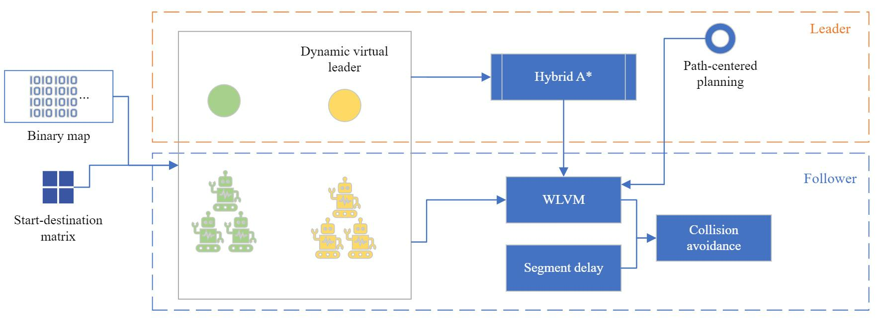
10], and this paper is an extension. The published paper introduces the concept of the novel Weight-Leader-Vicsek model, but it uses simple, straightforward path planning for the leader and traditional Vicsek update equations for followers. Nevertheless, this paper uses a dual layer to improve the model as an enhanced Weight-Leader-Vicsek model (WLVM). It generates the dynamic virtual leader by the hybrid A* algorithm and uses a start–destination matrix to determine the swarms’ integration, and collision avoidance is achieved by priority. Also, the followers’ position and angle updates are improved by adding the weight for the average angle and considering the current leader’s angle. The simulations are conducted in a new scenario, and WLVM is compared with other algorithms.
This paper offers a multi-AGV path-planning approach for optimizing automatic transportation in commercial or industrial warehouses. The paper is organized as follows. Section 2 reviews path-planning algorithms and the multi-AGV navigation approaches. Weight-Leader-Vicsek model is proposed in Section 3 for multi-AGV path planning and navigation. Experiment results are demonstrated in Section 4 to validate the approach, and the conclusion is in Section 5.

3. WLVM with Virtual Leaders and Weight

3.1. Preliminary Knowledge: Vicsek Model

The Vicsek model is introduced for particles with biologically motivated interaction with self-ordered motion and is proposed in [41]. The Vicsek model can be expressed by (1) and (2), and the algorithm is shown in Algorithm 1. Biological subjects spin in the same direction and move as their neighbourhood for interaction in an L L square region [41,42]. For a multi-agent system, the Vicsek model has been improved by taking a fixed number of neighbours and a percentage of neighbours into account as the remote neighbours’ strategy [43]. The hierarchical Weighting Vicsek model is proposed for flocking navigation, and it assigns different layers for the drones with weights to enhance the convergence speed, analyzing the involved parameters [44].
x i ( t + 1 ) = x i ( t ) + v i ( t ) Δ t
θ i ( t + 1 ) = θ ( t ) r + Δ θ
where x i ( t + 1 ) is the location of the particle i, the velocity v i is gained through an absolute velocity, and the angle is represented by θ i ( t + 1 ) . θ ( t ) r represents the average angle of the neighbouring particles within a circle with radius r. Δ θ denotes a random number from [ η 2 , η 2 ] as noise.
Algorithm 1: Vicsek model
1 Initialize parameters
2for  t i m e 1 to t i m e m a x do
3 Calculate averageTheta
4 x x + v e l c o s ( t h e t a ) d t
5 y y + v e l s i n ( t h e t a ) d t
6 t h e t a a v e r a g e T h e t a + n o i s e
7end

3.2. Problem Statement

The basic components of AGV path planning include the start, the target, and the environment. Path planning aims to generate the path from the start to the target without collisions. Figure 1 indicates an example of AGV path planning. As the occupancy map, the map uses the binary number to represent the locations in a 2D space. It can be transformed into a grid map or nodes for performing the heuristic or other path-planning algorithms. The obstacles or the walls are annotated in black.
Figure 1. Path planning in the map.
The AGV is supposed to move from the start to the target, and green points demonstrate the path points. The obstacles or walls are treated as static obstacles, and the generated path should not be overlapped with the static obstacles. The path points are represented by r 1 k , r 2 k , , r n k . r is the position of the current iteration k for nth AGV, and r n k is ( x n k , y n k ) .
Collision and deadlock avoidance are necessary for the multi-AGV system. Each AGV is assumed to communicate with other AGVs treated as dynamic obstacles. The deadlock of AGVs should be avoided for great system performance, and the adjusting progress is based on priority. The adjusted position of AGV n is represented by r n n e w .

3.3. Algorithm Description

3.3.1. Overview

WLVM is proposed for a multi-AGV path-planning algorithm to improve the Vicsek model because the Vicsek model cannot achieve practical path planning in the industry. WLVM assigns the virtual leaders to collaborate with the grouped AGVs and guide the followers to reach their destinations, considering collision avoidance.
Figure 2 describes the process of WLVM. According to a real industrial environment, the storage map is generated. Points represent the map; 0 is open space for movement, whereas 1 represents the wall or obstacles. The number of AGVs, velocities, angles, and locations are set for model initialization. The AGVs are divided into swarms based on their locations and destinations with assigned virtual leaders. The positions and angles of virtual leaders are computed by the hybrid A* algorithm. The follower-AGVs use the status of the leader in the current group to obtain the average angle within the defined path for WLVM. The AGVs implement a segment delay function to be separated by a certain distance for optimal arrangements. The AGVs avoid vehicle congestion and deadlock. Ref. [10] presents the design of the model for the AGV system.
Figure 2. WLVM process.
Table 1 saves the positions and angles of each swarm during the path-planning process. N stands for the number of the AGVs, and V i r t u a l   L e a d e r represents the leader in the group. WLVM saves the positions and angles for follower-AGVs and virtual leaders in each iteration and is used for further updating.
Table 1. AGV navigation data in the same group.

3.3.2. Dynamic Virtual Leader

Dynamic virtual leaders are implemented in WLVM for shorter paths, faster convergence, and more accurate direction for planning the path to arrive at the destination. Each multi-AGV group has one virtual leader. Figure 3 demonstrates the principle of the dynamic virtual leader. When a new AGV joins the current group, the AGVs of the multi-AGV group will treat it as part of the current group, and the group dynamically generates the virtual leader. The virtual leaders are generated in a static environment. When the AGVs aim for different areas, the start–destination matrix makes the separation, which refers to Section 3.3.3.
Figure 3. Principle of WLVM.
The positions for each AGV are calculated by (3). The equations for calculating the angles for follower AGVs are as (4).
x i k + 1 y i k + 1 = x i k y i k + v Δ t · c o s θ i k s i n θ i k
θ i k + 1 = ω 1 · a r c t a n s i n ( θ i k ) p c o s ( θ i k ) p + ω 2 · θ l k + 1 + η i k
where the average direction a r c t a n s i n ( θ i k ) p c o s ( θ i k ) p is estimated along the path p, and the travel distance is represented by v Δ t . η i k denotes the noise. w 1 is a random number in ( 0 , 1 ) , and the sum of w 1 and w 2 is 1. The swarm only considers the AGVs in the defined path in the same direction. The hybrid A* algorithm is integrated to calculate the position and angles for virtual leaders, and θ l k + 1 denotes the angle of the leader in the current iteration. It is adapted for multi-task implementation for virtual leaders.
When an AGV joins a new group, the virtual leader of that group will change if the AGV’s destination aligns with the group’s destination. If not, the group’s structure and leader remain unchanged. The leaders are predefined, while the followers keep gaining statuses from the neighbourhoods and then updating their status. It provides the possibility of real-time implementation.
For virtual leaders, angles and positions are generated by the hybrid A* algorithm, and the pseudo-code is indicated in Algorithm 2. A* is a widely used graph traversal algorithm because of optimal efficiency and completeness [45]. The hybrid A* algorithm is proposed in [46], which guarantees kinematic feasibility and continuous nature [47]. The heuristics are the maximum non-holonomic-without-obstacles and obstacle map, ignoring the nonholonomic nature [46]. The MATLAB navigation toolbox has the function for the hybrid A* algorithm.
Algorithm 2: Hybrid A*
1 Initialization of openset, closeset
2 openset.push(start)
3while openset is not empty do
4 x c u r r e n t o p e n s e t . p o p M i n C o s t N o d e
5if exists RS path then
6 return the path
7end
8for  x n e x t calculated by kinematic equation do
9 Collision avoidance
10if  x n e x t  not exists in closeset then
11 g g ( x c u r r e n t ) + l ( x c u r r e n t , x n e x t )
12 if  x n e x t  not exists in openset or g < g ( x n e x t ) then
13 g ( x n e x t ) g
14 h ( x n e x t ) H e u r i s t i c ( x n e x t , x g o a l )
15 P r e d ( x n e x t ) x c u r r e n t
16 if  x n e x t  not exists in openset then
17 openset.push( x n e x t )
18 else
19 openset.update(next node)
20 end
21end
22 end
23end
24end
The hybrid A* and WLVM combination is shown in Figure 4, and the proposed WLVM is in Algorithm 3. The leaders are generated for each swarm, and they are unique. For the generated path for followers, the path needs to be smooth by the Spline curve for AGVs to operate. The leaders will be regenerated if the environment or group formation changes. The statuses of AGVs are defined as (5). The statuses of AGVs are dynamically assigned based on their roles in the current swarm. Once the AGV arrives at the destination, the status is −1.
s t a t u s = 1 , if l e a d e r 0 , if f o l l o w e r 1 , if a r r i v e s
Figure 4. Dual layer of WLVM.
Algorithm 3: WLVM.
Data: x, y, leaderStart, leaderTarget
1 Initialize parameters
// ( n - the number of particles
2 n s i z e ( x , 2 ) + 1
3 d t 1
4 c h a n g e 1
5 x x l e a d e r S t a r t x
6 y y l e a d e r S t a r t y
7 t h e t a z e r o s ( 1 , n )
8for  i 1  to n do
9 t h e t a ( i ) l e a d e r S t a r t t h e t a
10end
11while change > 0 do
12 c h a n g e c h a n g e 1
13for each changed swarm do
// ( getting the positions and angles for the virtual leader
14 [ L e a d e r P o s , L e a d e r A n g l e ] H y b r i d A s t a r
15for  t i m e 1 to t i m e m a x  do
16 Calculate averageTheta
17 x x + v e l c o s ( t h e t a ) d t
18 y y + v e l s i n ( t h e t a ) d t
19 t h e t a w 1 a v e r a g e T h e t a + w 2 l e a d e r A n g l e ( t i m e ) + n o i s e
20 Smoothen path
21 Deadlock and collision avoidance
22end
23 Segment delay
24end
25 Swarm evaluation
26if swarm changes then
27 c h a n g e c h a n g e + 1
28end
29end

3.3.3. Start–Destination

WLVM can handle the multi-agent motion directed to different areas, as shown in Figure 5. The start–destination matrix is saved in Table 2. It assigns the multi-AGV groups, determines each group’s destination, treats them as other swarms, and does not integrate them. M stands for the number of leader-AGVs, which is much less than the number of follower-AGVs. S t a r t and D e s t i n a t i o n represent each leader’s origin and destination locations.
Figure 5. Groups with a different direction.
Table 2. Start–destination matrix.
Keep updating positions and directions within the defined group based on the destination flag. When AGVs are in operation, they only consider the AGVs along the path in the same direction. Even if the other path with a different direction is closer, the AGVs would not be generated. It only concerns the AGVs on the current path.

3.3.4. Segment Delay

The proposed WLVM enables AGVs to travel as a swarm and reach the target, which results in inefficiency for loading and unloading, so segment delay is introduced to solve this problem. Segment delay allows for the spacing of AGVs to avoid them arriving simultaneously. This facilitates organized loading and unloading operations. Figure 6 indicates the operation of segment delay, and it sets segment delay as two segments. Each AGV follows the defined path with a different segment delay for departure in each swarm. The segment delay is set as five segments in the computational experiments to provide the buffer area among AGVs.
Figure 6. The positions after setting segment delay as two segments.

3.3.5. Collision Avoidance

Obstacle Avoidance

Collision avoidance is necessary during the updating iterations to keep AGVs safe. There usually are some obstacles on the map in the practical implementation, so collision avoidance with the obstacles should be achieved. Collision avoidance of the virtual leaders is achieved by the hybrid A* algorithm. The follower-AGV utilizes the leader angle in the next iteration to determine the direction of the movement.
Figure 7 demonstrates the movement of the AGV. Each obstacle or wall sets the buffer area as 1m. The leader angle θ indicates the movement of the path, and AGV is represented by i. If a path point represented by r i ( x i , y i ) overlaps with the buffer area or the restricted area as the obstacles, it requires adjusting positions. The steps for achieving obstacle avoidance are as follows.
Figure 7. The AGV’s new position after collision avoidance.
First, comparing θ with 0. If θ 0 means the path is aimed to move upper/forward, then y i = y i + v y Δ t . Although θ < 0 means the path moves lower, then y i = y i v y Δ t . The AGVs follow the dotted line to change the Y locations. Second, comparing θ with π 2 or π 2 . If θ π 2 means the path is aimed to move left, then x i = x i v x Δ t . Although θ π 2 , which means the path is moving right, then x i = x i + v x Δ t . The AGVs follow the dotted line to change the X locations.

Deadlock Avoidance

The other AGVs in the predictable path or the moving obstacles are treated as dynamic obstacles. As shown in Figure 8, vehicle congestion must be avoided. The target location reserves only one vehicle in each iteration to avoid deadlock. The strategies to deal with the moving obstacles, except for other AGVs, refer to the previous section.
Figure 8. The AGV’s new position after deadlock avoidance.
Deadlock avoidance involves priorities for AGVs, and high priority is assigned when AGVs carry goods close to the destination or have urgent tasks. The AGV with higher priority remains following the predicted path, whereas the other AGV moves to an available position. The priority is calculated based on (6), and the new position is gained by (7). The new position is updated in the robot’s path after ensuring it is available.
p r i o r i t y i = ω 1 · p r i o r i t y t a s k + ω 2 · d i s t a n c e
r i n e w k + 1 = r i k + 1 + r a n d
where i stands for the current robot, and d i s t a n c e is the distance from the current position to the destination. p r i o r i t y t a s k represents the priority of each assigned task, and if the task is more urgent than others, p r i o r i t y t a s k is higher. w 1 and w 2 are the weight of each factor, the sum of w 1 and w 2 is 1. r i n e w stands for a new position of the robot i.

3.4. Comparison

The proposed WLVM implements dynamic swarms and virtual leaders to ensure accurate direction and faster convergence, considering collision avoidance, the start–destination matrix to distinguish the destinations of swarms and the applications of multi-objective algorithms in the industrial environment. Figure 9 shows the advanced functionality of the WLVM. It also provides flexibility because of the dynamic swarms involved, and the follower-AGV can join or disconnect from the current group. The AGVs are assumed to exchange information during operations; if one AGV enters another area, it becomes a member of the new group.
Figure 9. Comparison of Vicsek model and WLVM.
The WLVM is novel for multi-AGV navigation, and it adapts the biological pattern because it achieves the path planning of several AGVs in one step. The traditional Vicsek model can describe the multi-agent movement, which is enhanced to improve WLVM. Following the biological pattern, AGVs move automatically as their neighbours do in the same direction if operating the same task. It is typical to involve several AGVs for one task; the improved WLVM achieves fast multi-AGV path planning by updating the positions and angles. It only requires calculation for the virtual leaders in the leader layer and one calculation step in the follower layer. Even though the number of AGVs is large, it obtains the path with a quick calculation.

4. Computational Experiments

4.1. Experiment Settings

Figure 10 generates the warehouse map and denotes the initial locations of AGVs; different colours indicate the different swarms. WLVM is validated through MATLAB. The start–destination matrix separates the swarms. Each delivery group is operating in Area A.
Figure 10. The path for virtual leaders.
The multi-AGV system is engaged for deliveries from Area A because the three-dimensional storage system is implemented in the primary storage rooms: Area B to Area F. The materials are placed on the platform to transfer to the defined location by the pallet in the three-dimensional storage system.
Assumptions in the simulation are as follows:
  • 7 AGVs depart from Area A to different storage areas for processing tasks, and 4 AGVs move to Area A for parking;
  • Set segment delay for five segments in each swarm;
  • AGVs with an absolute velocity of 1 m/s;
  • Each AGV is equipped with a board that can operate WLVM;
  • Each AGV has onboard sensors for localization and obstacle detection;
  • Each AGV communicates with other AGVs, sending its positions, angles and statuses.
The groups’ settings are listed in Table 3.
Table 3. Group settings.

4.2. Results

4.2.1. Simulation

Figure 10 displays the path for the virtual leaders generated by the hybrid A* algorithm after the group changes. The directions are indicated along with the path. It also outlines the path area for each swarm. The blue path is from Area A to Area E, and the orange path is from Area A to Area F. The purple path is from Area B to Area A, and the green path is from Area C to Area A. Groups 1 and 2 from Area A are separated based on the simulation’s destination. Groups 3 and 4 are merged into one group when they are close to each other and aim for the same destination.
Figure 11 shows the AGVs’ paths. When two delivery groups pass the same area, collision avoidance ensures that AGVs operate safely. The start–destination matrix has played a role in distinguishing the multi-AGV group. The groups of inbound delivery are aimed at different main storage rooms with different virtual leaders. When the group arrives at the destination, the group is reminded of the current state, and the moving AGVs achieve collision avoidance based on the priorities.
Figure 11. AGV positions during the path-planning process and the grey areas indicate the packing areas.
The following Table 4 lists the performance measurements. The group number is assigned according to the respective swarms. The distance is the travelling distance for each AGV in the group, which refers to the distance each AGV must travel to accomplish its assigned task. The time is the consumed time for each swarm to complete the task.
Table 4. Performance measurements.

4.2.2. Experiment

The results of the simulation section are validated by the experiment with the Raspberry Pi robot and Ultra-Wide Band (UWB) for positioning. UWB provides centimetre-level positioning and high positioning accuracy in the indoor environment. The robot follows the designed path gained by the simulation.
The experiment used the AGVs from Group 1, the inbound delivery group from Area A to Area E, with 4 AGVs. They followed the defined paths and gained positioning data from the positioning sensor. The positioning results were collected from the Decawave UWB sensors, and the robot carries the target for getting locations. The iterations of the results shown in Figure 12 are t = 0 , t = 25 , and t = 49 . The start positions are indicated as t = 0 , and the destinations are shown when t = 49 . The locations have some bias due to the sensor accuracy, which can be fixed by sensor fusion in future work.
Figure 12. UWB positions following the generated path.

4.3. Comparison

The proposed WLVM is compared with the RRT* algorithm [48] and an improved APF with deterministic annealing (DA-APF) [49] for path planning in Group 1, with a segment delay of five segments. The comparison of the runtime is listed in Table 5. RRT is a sampling-based algorithm that is popular for multi-constrained and high-dimensional path planning [50]. Sampling-based planners connect samples by constructing trees iteratively from the sampling distributions, and the planners deterministically or probabilistically draw random samples. APF uses attractive and repulsive potentials and treats the robot as an affected object. Wu et al. [49] apply a deterministic annealing strategy to improve the classical APF algorithm for path planning, changing the temperature parameters.
Table 5. Runtimes for the RRT*, DA-APF, and WLVM algorithms.
The RRT* and DA-APF algorithms need to repeat the calculation for each AGV, whereas WLVM calculates the path for all AGVs at one step. WLVM provides fast path planning due to the computational speed. Figure 13 shows the AGV positions generated by the RRT* and DA-APF algorithms. Figure 13a shows the positions generated by the RRT* algorithm for t = 25 that are marked by different colours and the last positions when t = 64 that are marked by blue. If the number of AGVs dramatically rises, the computation time for the RRT* algorithm will rise rapidly, whereas it would not affect WLVM. Figure 13b indicates the path generated by the DA-APF algorithm. Although DA-APF achieves fast computation, it is still slower than WLVM for grouped AGVs.
Figure 13. AGV positions generated by other algorithms.

5. Conclusions

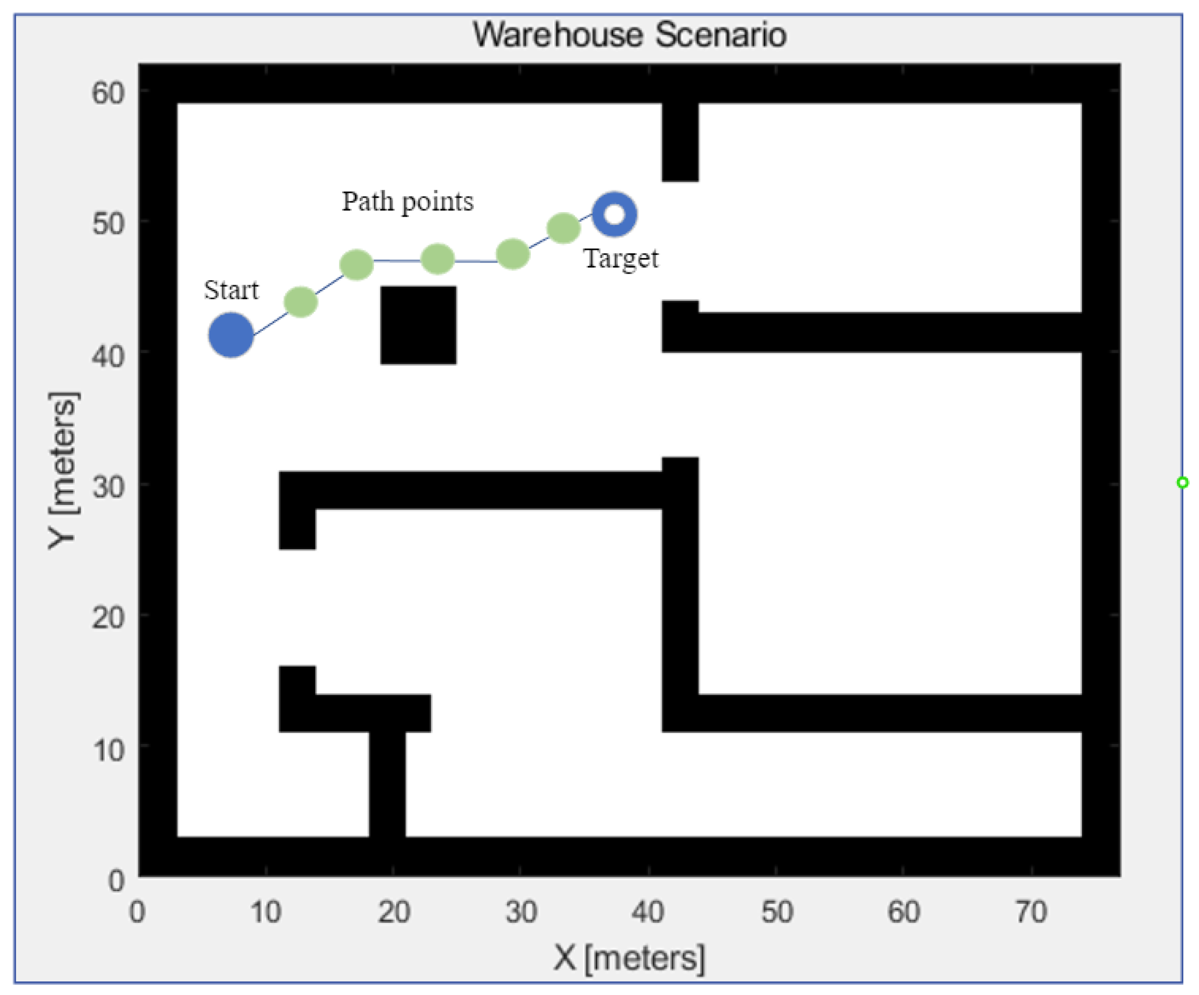
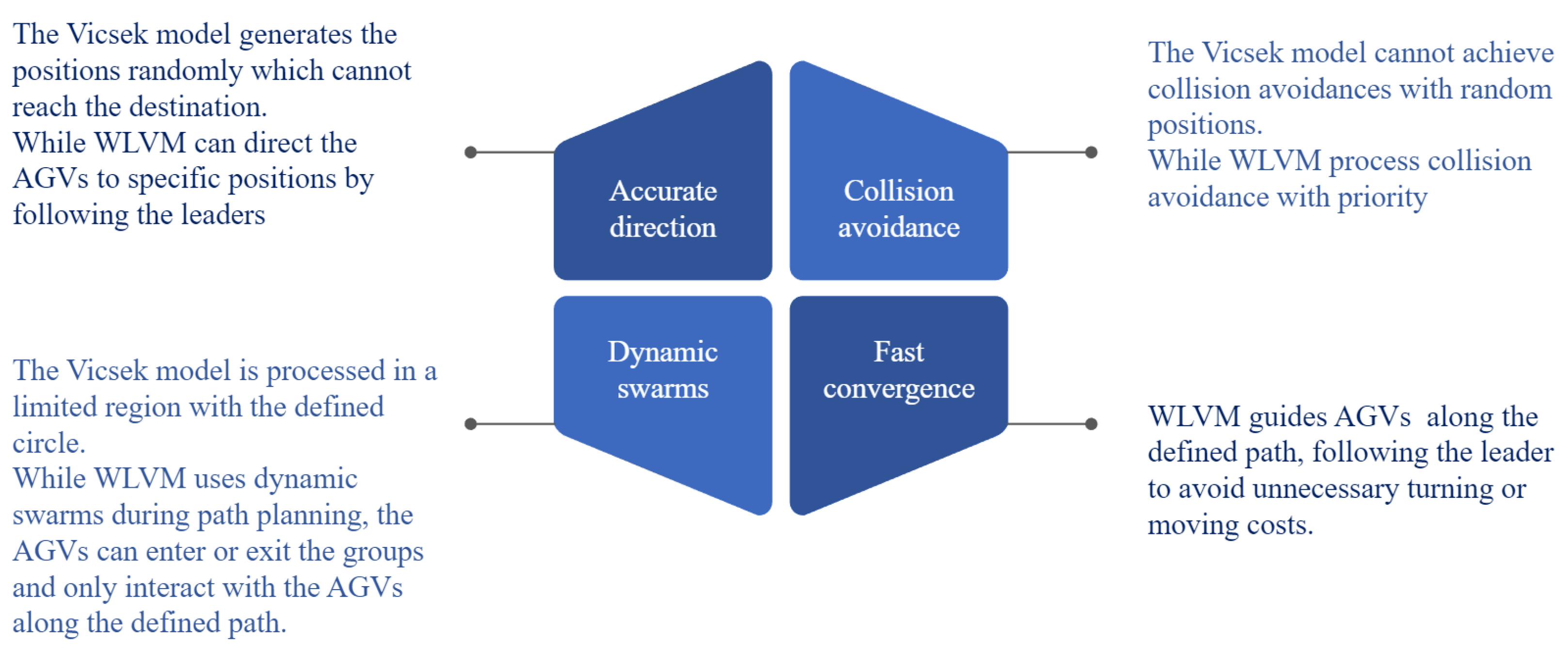
The WLVM is proposed to improve the Vicsek model, and it develops dynamic virtual leaders and a start–destination matrix, considering the leaders’ direction with weight. Also, it is capable of providing scalability and flexibility for multi-AGV systems with fast and flexible path settings. The path-planning problem is formulated as a 2D space with the start and target locations, and it avoids static and dynamic obstacles. From the literature, most path-planning approaches plan the path independently. However, the proposed WLVM algorithm can offer the path settings in one calculation step for swarms.
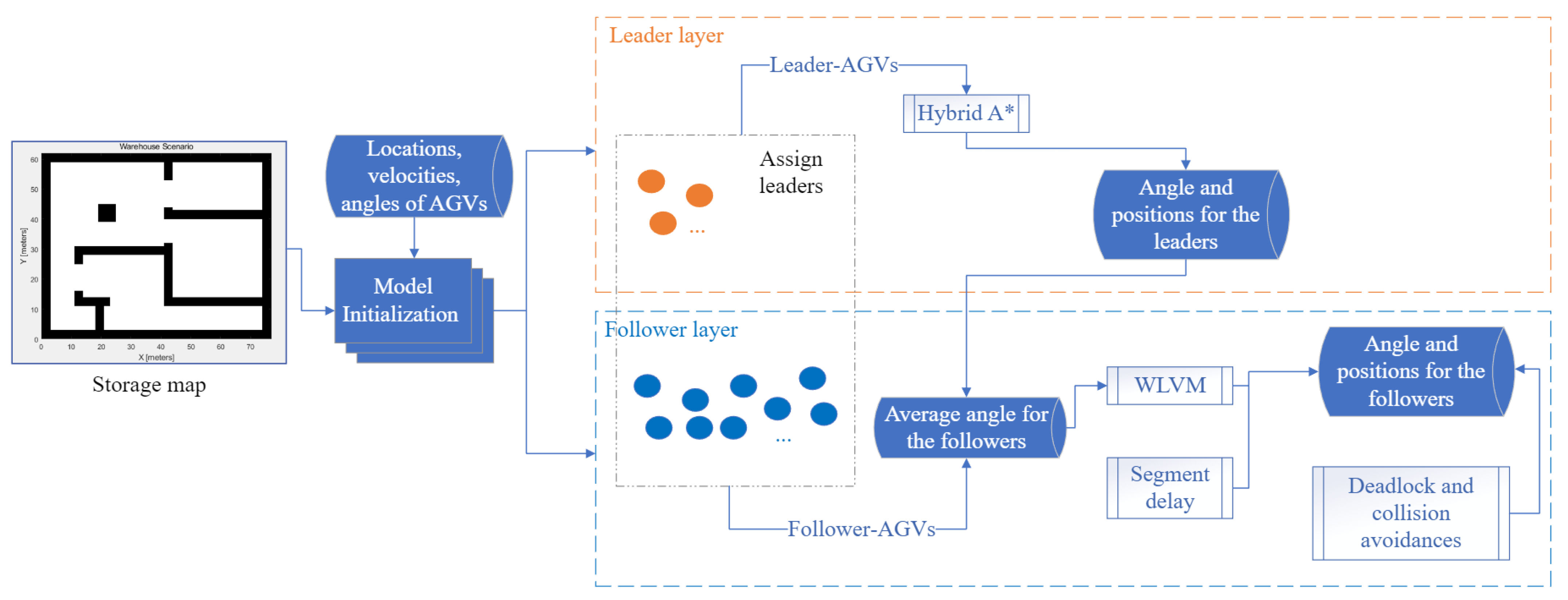
The WLVM implements the virtual leader to navigate the follower-AGV in each multi-AGV group, and the leader’s positions and angels are generated by the hybrid A* algorithm. The proposed approach updates the statutes of AGVs with iterations, and the angles of AGVs consider the neighbour and the leader. Model and system initialization and multi-AGV group formation are completed through a centralized method, whereas it achieves the dynamic decentralized approach for each AGV.
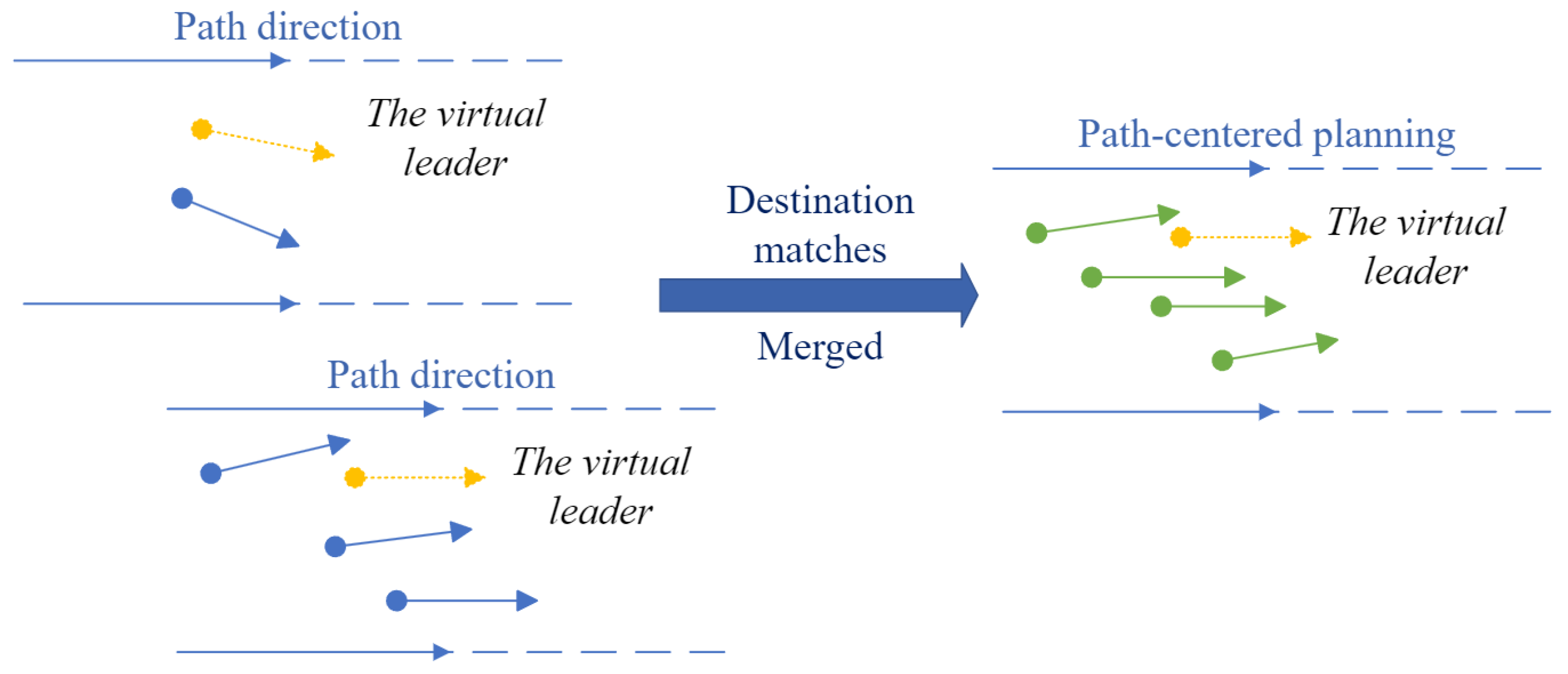
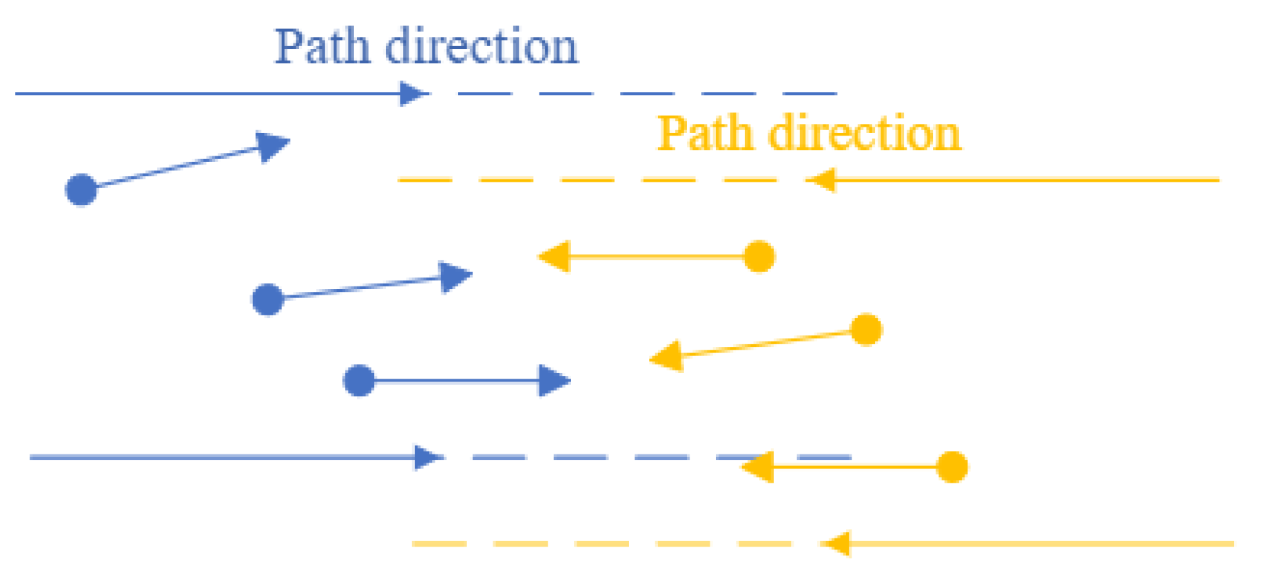
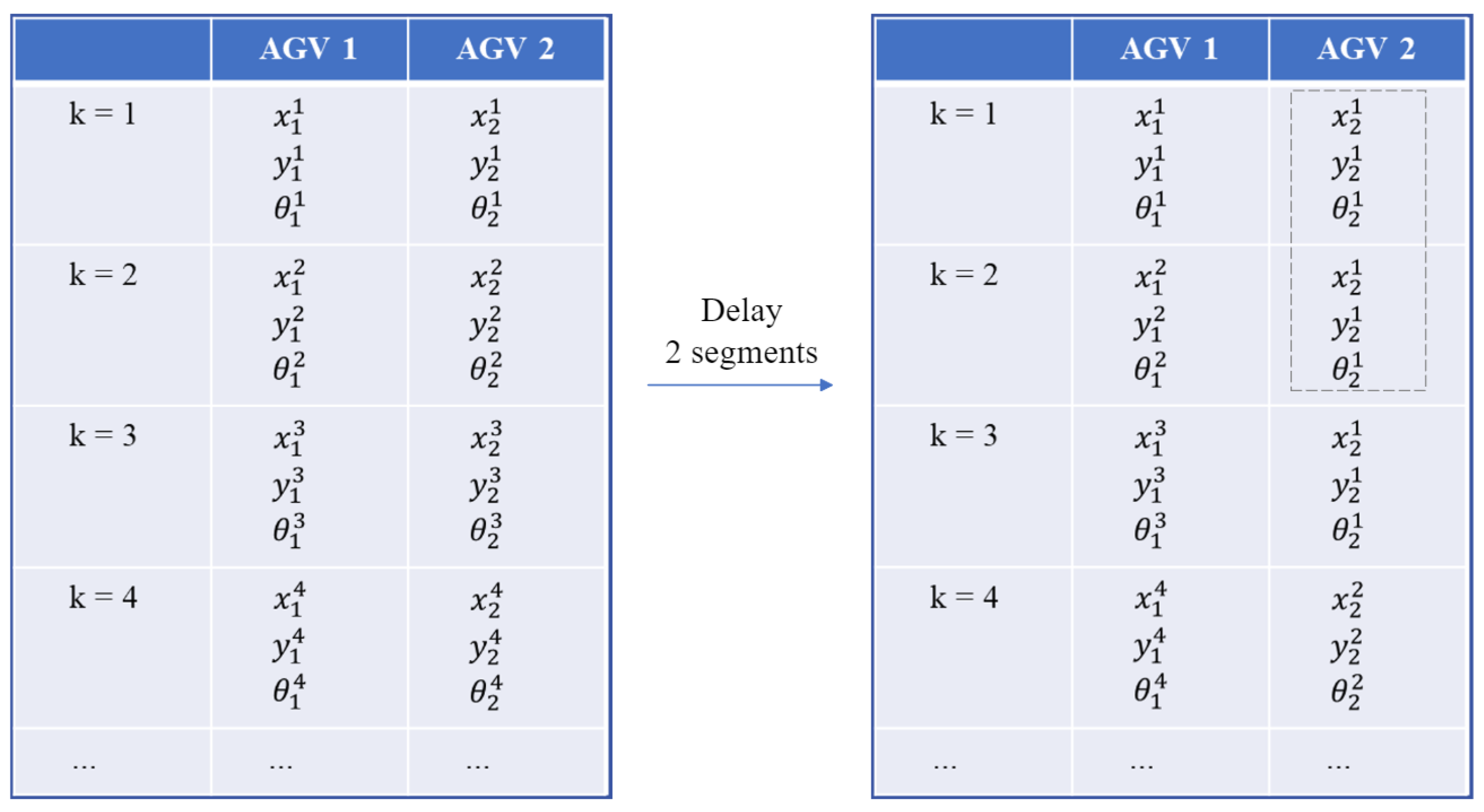
It computes the follower-AGVs’ path with a quick computation, even though the number of AGVs is large. Unnecessary turning costs and path segments are avoided in this model. Each AGV only considers its neighbours in the path and tends to move as its neighbours. For swarm integration or separation, the start–destination matrix plays a role. It determines whether the multi-AGV group is aimed at the same destination and makes changes in the decentralized follower layer. Segment delay is implemented for optimal arrangement between AGVs for loading.
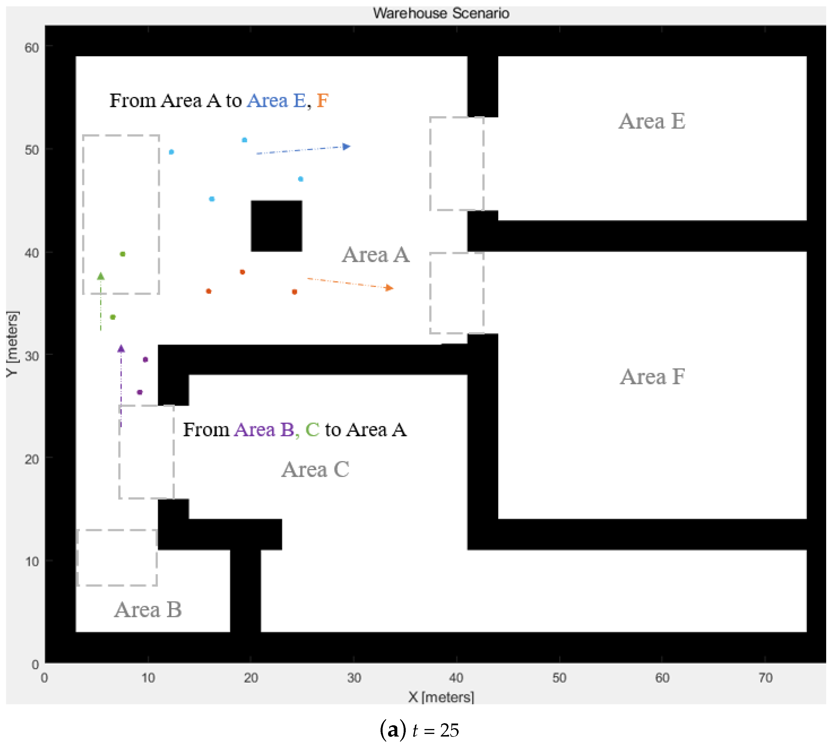
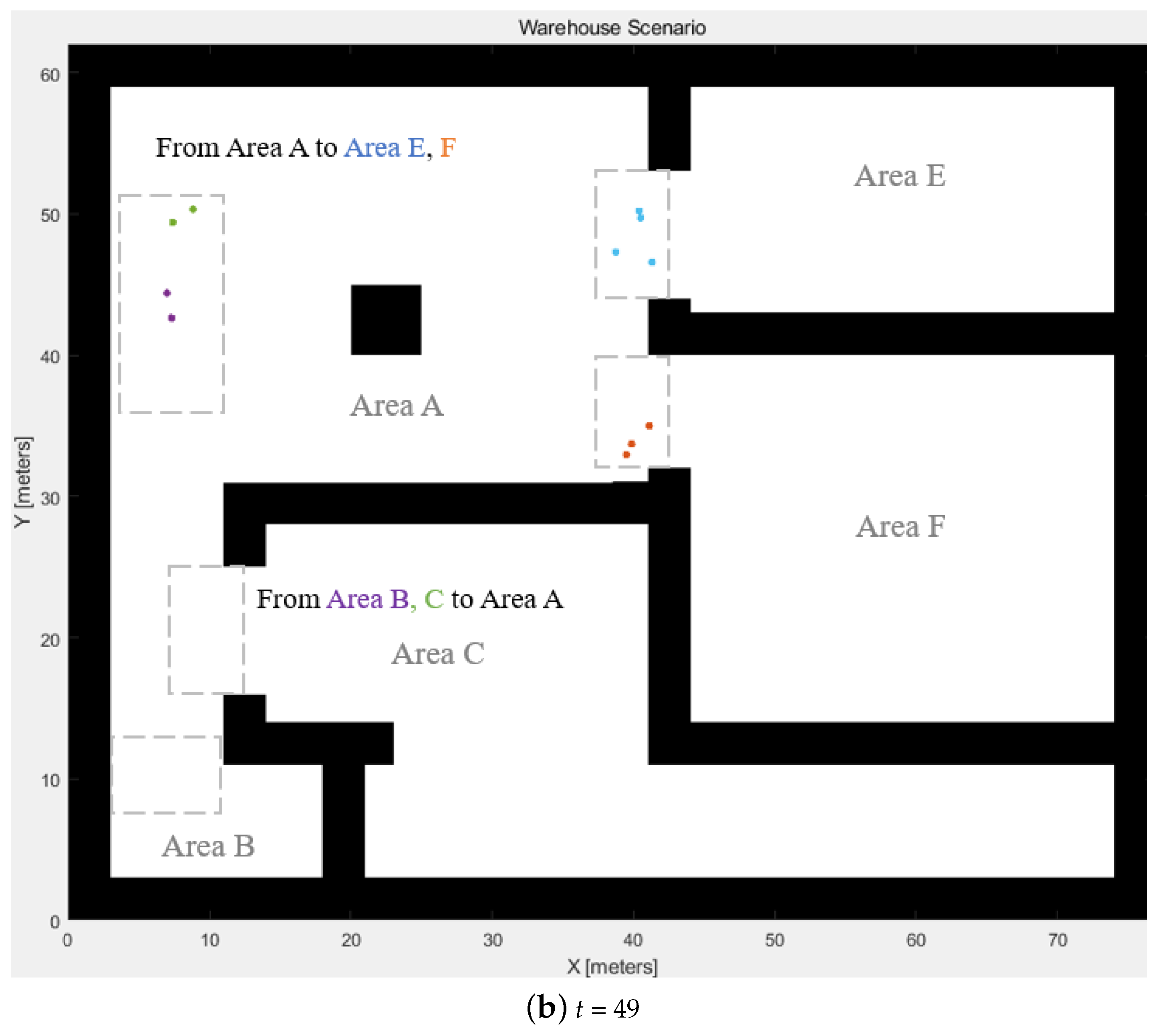
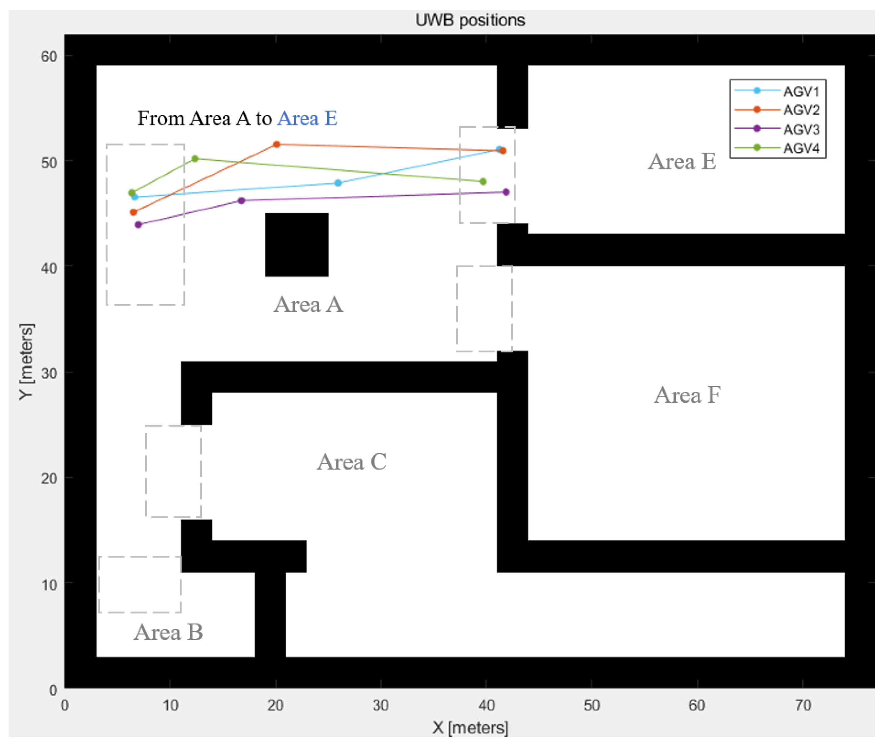
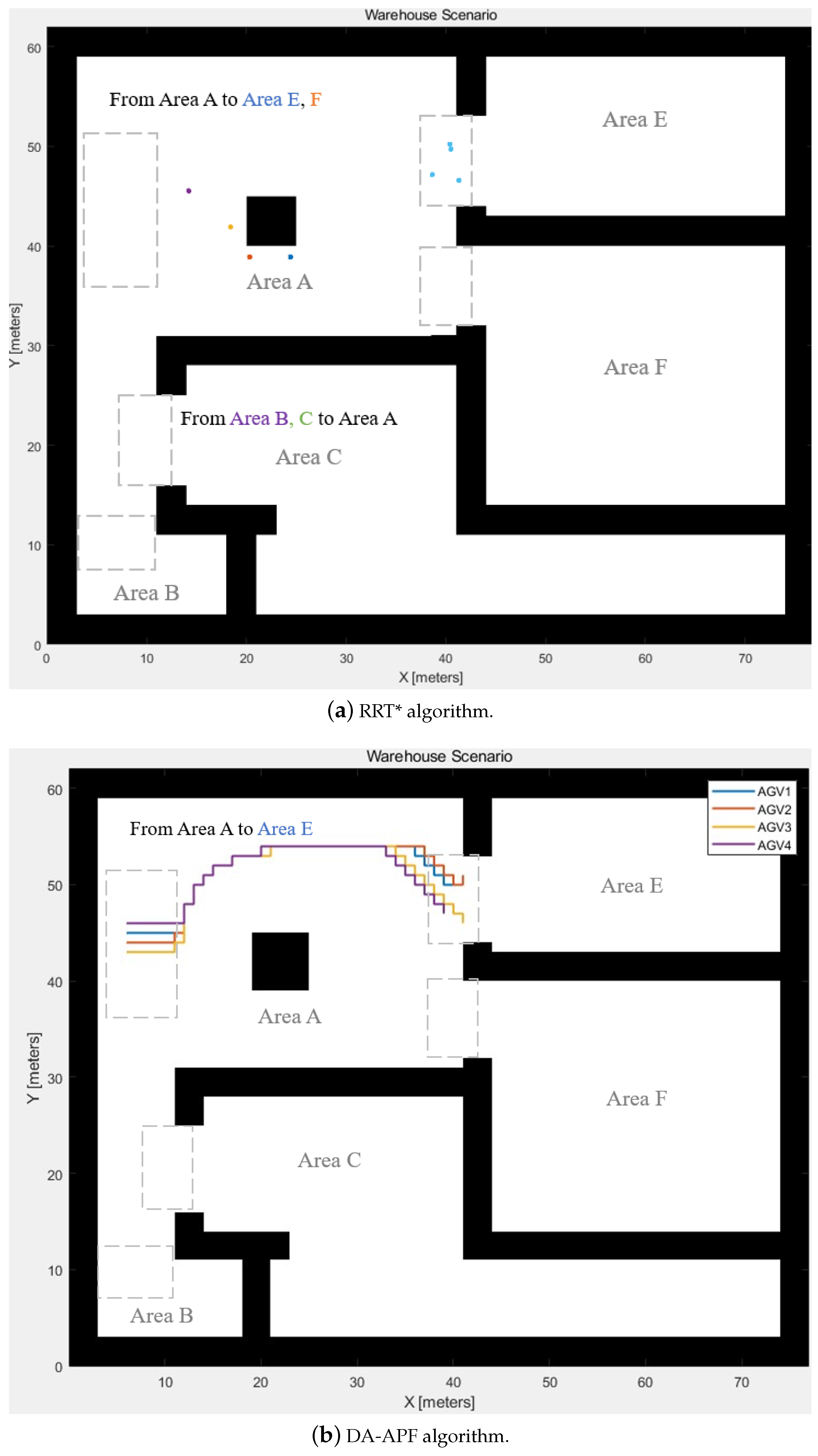
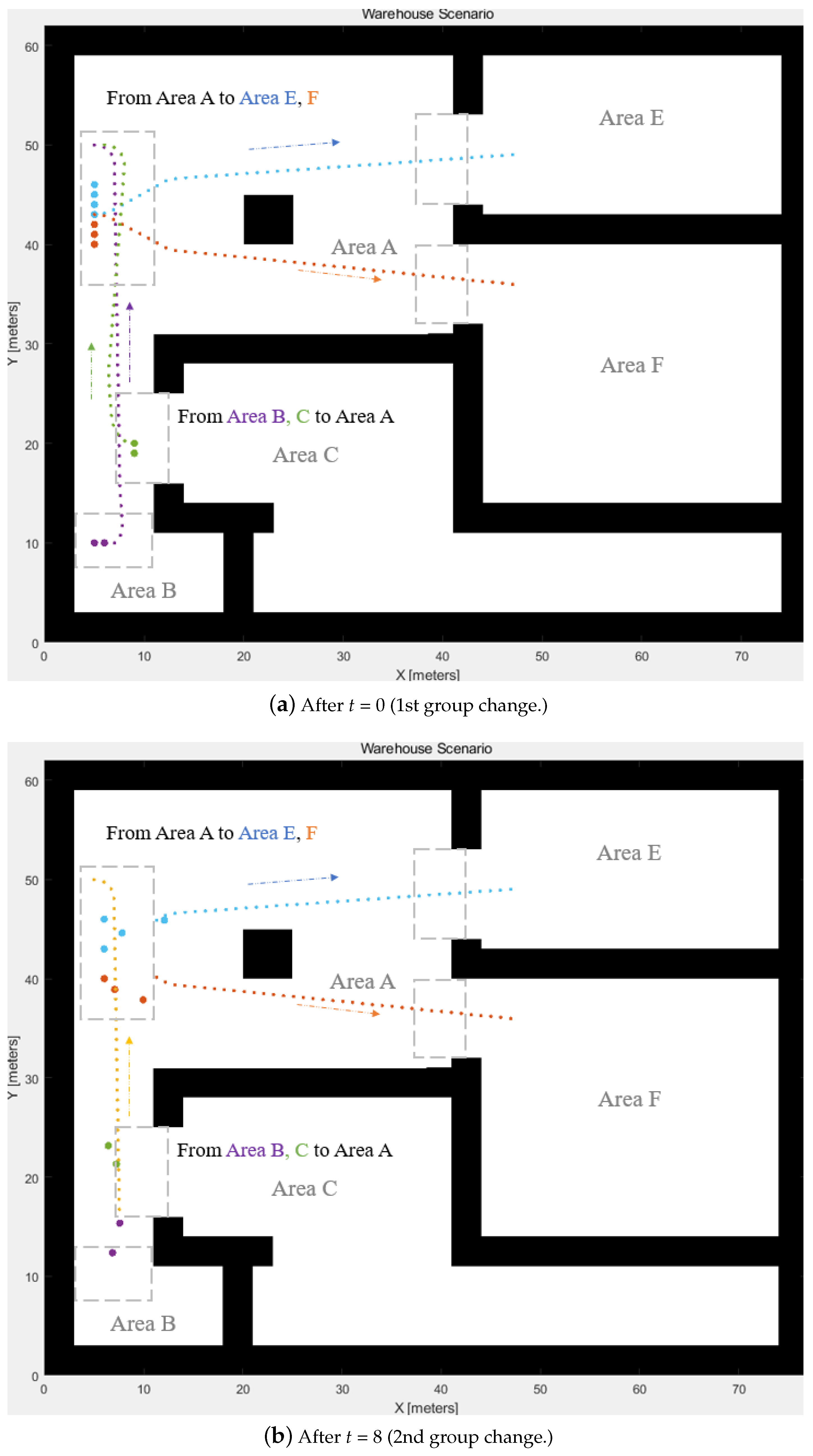
The proposed WLVM has the following benefits: accurate direction, dynamic swarms, fast convergence, and collision avoidance. It can achieve real-time implementation due to its computational speed and robust implementation. For the computational experiment, four groups with different settings demonstrate swarm separation and integration. The proposed algorithm is compared with other algorithms for path planning of four AGVs; the WLVM saves 98.39% and 47.41% computational time than the RRT* and DA-APF algorithms, respectively. WLVM is robust and simple for implementation during the AGVs’ or robots’ operations. The proposed algorithm can be applied to various scenarios involving the system of multiple robots, such as warehouses, logistics systems, ports, and airports.
The limitation of the proposed approach is that it does not consider the cost value during the path planning as the heuristic methodologies. Therefore, the generated path cannot be measured or estimated with the specific costs to determine whether the path is globally optimal. The robot’s dynamics and different speed scenarios must be considered during the real-world application. With the following considerations, WLVM would be more practical in the industrial environment for future work. Mission planning and task allocation can be included in the further improvement of this model. The multi-AGV system would be more practical if it involves fault tolerance during implementation. The combination of sensors and the sensor-fusion algorithm could be considered in further real experiments to estimate the angle and the position and detect and avoid obstacles. Implementing a neural network for the path-planning approach can be considered a potential improvement.

Author Contributions

Conceptualization, S.L.; methodology, S.L.; software, S.L.; validation, S.L.; formal analysis, S.L.; investigation, S.L.; resources, S.L.; data curation, S.L.; writing—original draft preparation, S.L.; writing—review and editing, S.L., A.L., and J.W.; visualization, S.L.; supervision, J.W.; project administration, S.L.; funding acquisition, S.L. and J.W. All authors have read and agreed to the published version of the manuscript.

Funding

This research received no external funding.

Institutional Review Board Statement

Not applicable.

Data Availability Statement

Data are contained within the article.

Conflicts of Interest

The authors declare no conflict of interest.

Abbreviations

The following abbreviations are used in this manuscript:
AGVAutomatic guided vehicles
Multi-AGVMultiple automatic guided vehicles
WLVMWeight-Leader-Vicsek Model
RRTRapidly-exploring random trees
WMSWarehouse management system
DA-APFAPF algorithm based on deterministic annealing

References

  1. Liu, J.; Jayakumar, P.; Stein, J.L.; Ersal, T. A nonlinear model predictive control formulation for obstacle avoidance in high-speed autonomous ground vehicles in unstructured environments. Veh. Syst. Dyn. 2017, 56, 853–882. [Google Scholar] [CrossRef]
  2. Yuan, Z.; Yang, Z.; Lv, L.; Shi, Y. A Bi-Level Path Planning Algorithm for Multi-AGV Routing Problem. Electronics 2020, 9, 1351. [Google Scholar] [CrossRef]
  3. Guo, X.; Ren, Z.; Wu, Z.; Lai, J.; Zeng, D.; Xie, S. A Deep Reinforcement Learning Based Approach for AGVs Path Planning. In Proceedings of the 2020 Chinese Automation Congress (CAC), Shanghai, China, 6–8 November 2020; pp. 6833–6838. [Google Scholar] [CrossRef]
  4. Lynch, L.; Newe, T.; Clifford, J.; Coleman, J.; Walsh, J.; Toal, D. Automated Ground Vehicle (AGV) and Sensor Technologies—A Review. In Proceedings of the Twelfth International Conference on Sensing Technology (ICST), Limerick, Ireland, 4–6 December 2018; pp. 347–352. [Google Scholar]
  5. Cramer, M.; Cramer, J.; De Schepper, D.; Aerts, P.; Kellens, K.; Demeester, E. Benchmarking low-cost inertial measurement units for indoor localisation and navigation of AGVs. Procedia CIRP 2019, 86, 204–209. [Google Scholar] [CrossRef]
  6. Kostov, M.; Kostova, V.; Markoska, R. AGV guidance system simulations with a programmable robotics kit. Int. J. Reason.-Based Intell. Syst. 2015, 7, 42–46. [Google Scholar] [CrossRef]
  7. Cui, Z.; Xu, H.; Chen, Z.; Yang, H.; Huang, S.; Gong, M. Design of a novel AGV with automatic pick-and-place system based on scissor lifting platform. In Proceedings of the 2020 Chinese Automation Congress (CAC), Shanghai, China, 6–8 November 2020; pp. 4435–4440. [Google Scholar] [CrossRef]
  8. Zacharia, P.T.; Xidias, E.K. AGV routing and motion planning in a flexible manufacturing system using a fuzzy-based genetic algorithm. Int. J. Adv. Manuf. Technol. 2020, 109, 1801–1813. [Google Scholar] [CrossRef]
  9. Li, P.; Xu, Y.; Shen, T.; Bi, S. INS/UWB integrated AGV localization employing Kalman filter for indoor LOS/NLOS mixed environment. In Proceedings of the International Conference on Advanced Mechatronic Systems (ICAMechS), Kusatsu, Japan, 26–28 August 2019; pp. 294–298. [Google Scholar]
  10. Lin, S.; Liu, A.; Kong, X.; Wang, J. Development of Swarm Intelligence Leader-Vicsek-Model for Multi-AGV Path Planning. In Proceedings of the 2021 20th International Symposium on Communications and Information Technologies (ISCIT), Tottori, Japan, 19–22 October 2021; pp. 49–54. [Google Scholar] [CrossRef]
  11. Wang, J.; Pan, J.; Huo, J.; Wang, R.; Li, L.; Nian, T. Research on Optimization of Multi-AGV Path Based on Genetic Algorithm Considering Charge Utilization. J. Phys. Conf. Ser. 2021, 1769, 12052. [Google Scholar] [CrossRef]
  12. Yadav, A.; Gaur, A.; Jain, S.M.; Chaturvedi, D.K.; Sharma, R. Development Navigation, Guidance & Control Program for GPS based Autonomous Ground Vehicle (AGV) using Soft Computing Techniques. Mater. Today Proc. 2020, 29, 530–535. [Google Scholar] [CrossRef]
  13. Cekmez, U.; Ozsiginan, M.; Sahingoz, O.K. A UAV path planning with parallel ACO algorithm on CUDA platform. In Proceedings of the 2014 International Conference on Unmanned Aircraft Systems (ICUAS), Orlando, FL, USA, 27–30 May 2014; pp. 347–354. [Google Scholar] [CrossRef]
  14. Digani, V.; Hsieh, M.A.; Sabattini, L.; Secchi, C. Coordination of multiple AGVs: A quadratic optimization method. Auton. Robot. 2018, 43, 539–555. [Google Scholar] [CrossRef]
  15. Kong, H.; Sun, J.; Hu, J. Real-time Motion Planning Based on Layered Cost Map for AGV Navigation. In Proceedings of the 2020 Chinese Automation Congress (CAC), Shanghai, China, 6–8 November 2020; pp. 7624–7628. [Google Scholar] [CrossRef]
  16. Xu, Z.; Liu, X.; Chen, Q. Application of Improved Astar Algorithm in Global Path Planning of Unmanned Vehicles. In Proceedings of the 2019 Chinese Automation Congress (CAC), Hangzhou, China, 22–24 November 2019. [Google Scholar] [CrossRef]
  17. Almurib, H.A.F.; Nathan, P.T.; Kumar, T.N. Control and path planning of quadrotor aerial vehicles for search and rescue. In Proceedings of the SICE Annual Conference 2011, Tokyo, Japan, 13–18 September 2011; pp. 700–705. [Google Scholar]
  18. Shi, Y.; Li, Q.; Bu, S.; Yang, J.; Zhu, L. Research on Intelligent Vehicle Path Planning Based on Rapidly-Exploring Random Tree. Math. Probl. Eng. 2020, 2020, 5910503. [Google Scholar] [CrossRef]
  19. Huang, T.; Huang, D.; Qin, N.; Li, Y. Path Planning and Control of a Quadrotor UAV Based on an Improved APF Using Parallel Search. Int. J. Aerosp. Eng. 2021, 2021, 5524841. [Google Scholar] [CrossRef]
  20. Xu, J.; Tian, Z.; He, W.; Huang, Y. A Fast Path Planning Algorithm Fusing PRM and P-Bi-RRT. In Proceedings of the 2020 11th International Conference on Prognostics and System Health Management (PHM-2020 Jinan), Jinan, China, 23–25 October 2020; pp. 503–508. [Google Scholar] [CrossRef]
  21. Draganjac, I.; Miklic, D.; Kovacic, Z.; Vasiljevic, G.; Bogdan, S. Decentralized Control of Multi-AGV Systems in Autonomous Warehousing Applications. IEEE Trans. Autom. Sci. Eng. 2016, 13, 1433–1447. [Google Scholar] [CrossRef]
  22. Lian, Y.; Xie, W.; Zhang, L. A Probabilistic Time-Constrained Based Heuristic Path Planning Algorithm in Warehouse Multi-AGV Systems. IFAC-PapersOnLine 2020, 53, 2538–2543. [Google Scholar] [CrossRef]
  23. Chen, X.; Wu, W.; Hu, R. A Novel Multi-AGV Coordination Strategy Based on the Combination of Nodes and Grids. IEEE Robot. Autom. Lett. 2022, 7, 6218–6225. [Google Scholar] [CrossRef]
  24. Xia, P.; Xu, A.; Zhang, Y. A Multi-AGV Optimal Scheduling Algorithm Based on Particle Swarm Optimization. In Artificial Intelligence and Security, Proceedings of the 6th International Conference, ICAIS 2020, Hohhot, China, 17–20 July 2020; Communications in Computer and Information Science; Springer: Singapore, 2020; Chapter 47; pp. 527–538. [Google Scholar] [CrossRef]
  25. Lian, Y.; Xie, W. Improved A* Multi-AGV Path Planning Algorithm Based on Grid-Shaped Network. In Proceedings of the 2019 Chinese Control Conference (CCC), Guangzhou, China, 27–30 July 2019; pp. 2088–2092. [Google Scholar] [CrossRef]
  26. Yang, Q.; Lian, Y.; Liu, Y.; Xie, W.; Yang, Y. Multi-AGV Tracking System Based on Global Vision and AprilTag in Smart Warehouse. J. Intell. Robot. Syst. 2022, 104, 42. [Google Scholar] [CrossRef]
  27. Xing, L.; Liu, Y.; Li, H.; Wu, C.C.; Lin, W.C.; Chen, X. A Novel Tabu Search Algorithm for Multi-AGV Routing Problem. Mathematics 2020, 8, 279. [Google Scholar] [CrossRef]
  28. Chen, J.; Zhang, X.; Peng, X.; Xu, D.; Peng, J. Efficient routing for multi-AGV based on optimized Ant-agent. Comput. Ind. Eng. 2022, 167, 108042. [Google Scholar] [CrossRef]
  29. Solichudin, S.; Triwiyatno, A.; Riyadi, M.A. Conflict-free dynamic route multi-AGV using dijkstra floyd-warshall hybrid algorithm with time windows. Int. J. Electr. Comput. Eng. (IJECE) 2020, 10, 3596–3604. [Google Scholar] [CrossRef]
  30. Zhao, Y.; Liu, X.; Wu, S.; Wang, G. Spare zone based hierarchical motion coordination for multi-AGV systems. Simul. Model. Pract. Theory 2021, 109, 102294. [Google Scholar] [CrossRef]
  31. Cardarelli, E.; Digani, V.; Sabattini, L.; Secchi, C.; Fantuzzi, C. Cooperative cloud robotics architecture for the coordination of multi-AGV systems in industrial warehouses. Mechatronics 2017, 45, 1–13. [Google Scholar] [CrossRef]
  32. Zheng, K.; Tang, D.; Gu, W.; Dai, M. Distributed control of multi-AGV system based on regional control model. Prod. Eng. 2013, 7, 433–441. [Google Scholar] [CrossRef]
  33. Zhang, Y.; Wang, F.; Fu, F.; Su, Z. Multi-AGV Path Planning for Indoor Factory by Using Prioritized Planning and Improved Ant Algorithm. J. Eng. Technol. Sci. 2018, 50, 534–547. [Google Scholar] [CrossRef]
  34. Cao, X.; Zhu, M. Research on global optimization method for multiple AGV collision avoidance in hybrid path. Optim. Control. Appl. Methods 2021, 42, 1064–1080. [Google Scholar] [CrossRef]
  35. Tao, L.; Zhang, S.; Chen, S.; Zheng, N. Multi-AGV pathfinding for automatic warehouse applications. In Proceedings of the 2021 China Automation Congress (CAC), Beijing, China, 22–24 October 2021. [Google Scholar] [CrossRef]
  36. Zhong, M.; Yang, Y.; Dessouky, Y.; Postolache, O. Multi-AGV scheduling for conflict-free path planning in automated container terminals. Comput. Ind. Eng. 2020, 142, 106371. [Google Scholar] [CrossRef]
  37. Liu, C.; Tan, J.; Zhao, H.; Li, Y.; Bai, X. Path planning and intelligent scheduling of multi-AGV systems in workshop. In Proceedings of the 2017 36th Chinese Control Conference (CCC), Dalian, China, 26–28 July 2017; pp. 2735–2739. [Google Scholar] [CrossRef]
  38. Yang, Y.; Zhang, J.; Liu, Y.; Song, X. Multi-AGV Collision Avoidance Path Optimization for Unmanned Warehouse Based on Improved Ant Colony Algorithm. In Bio-Inspired Computing: Theories and Applications, Proceedings of the 14th International Conference, BIC-TA 2019, Zhengzhou, China, 22–25 November 2019; Communications in Computer and Information Science; Springer: Singapore, 2020; Chapter 41; pp. 527–537. [Google Scholar] [CrossRef]
  39. Zając, J.; Małopolski, W. Structural on-line control policy for collision and deadlock resolution in multi-AGV systems. J. Manuf. Syst. 2021, 60, 80–92. [Google Scholar] [CrossRef]
  40. Digani, V.; Sabattini, L.; Secchi, C.; Fantuzzi, C. Ensemble Coordination Approach in Multi-AGV Systems Applied to Industrial Warehouses. IEEE Trans. Autom. Sci. Eng. 2015, 12, 922–934. [Google Scholar] [CrossRef]
  41. Vicsek, T.; Czirók, A.; Ben-Jacob, E.; Cohen, I.; Shochet, O. Novel Type of Phase Transition in a System of Self-Driven Particles. Phys. Rev. Lett. 1995, 75, 1226–1229. [Google Scholar] [CrossRef] [PubMed]
  42. Lu, X.; Zhang, C.; Huang, C.; Qin, B. Research on swarm consistent performance of improved Vicsek model with neighbors’ degree. Physica A 2022, 588, 126567. [Google Scholar] [CrossRef]
  43. Lu, X.; Zhang, C.; Qin, B. An improved Vicsek model of swarm based on remote neighbors strategy. Physica A 2022, 587, 126553. [Google Scholar] [CrossRef]
  44. Liu, X.; Xiang, X.; Chang, Y.; Chao, Y.; Tang, D. Hierarchical Weighting Vicsek Model for Flocking Navigation of Drones. Drones 2021, 5, 74. [Google Scholar] [CrossRef]
  45. Li, H.; Chu, Z.; Fang, Y.; Liu, H.; Zhang, M.; Wang, K.; Huang, J. Source-seeking multi-robot team simulator as container of nature-inspired metaheuristic algorithms and Astar algorithm. Expert Syst. Appl. 2023, 233, 120932. [Google Scholar] [CrossRef]
  46. Dolgov, D.; Thrun, S.; Montemerlo, M.; Diebel, J. Practical Search Techniques in Path Planning for Autonomous Driving. Ann Arbor 2008, 1001, 18–80. [Google Scholar]
  47. Petereit, J.; Emter, T.; Frey, C.W.; Kopfstedt, T.; Beutel, A. Application of Hybrid A* to an Autonomous Mobile Robot for Path Planning in Unstructured Outdoor Environments. In Proceedings of the ROBOTIK 2012, 7th German Conference on Robotics, Munich, Germany, 21–22 May 2012; p. 1. [Google Scholar]
  48. Karaman, S.; Frazzoli, E. Sampling-based algorithms for optimal motion planning. Int. J. Robot. Res. 2011, 30, 846–894. [Google Scholar] [CrossRef]
  49. Wu, Z.; Dai, J.; Jiang, B.; Karimi, H.R. Robot path planning based on artificial potential field with deterministic annealing. ISA Trans. 2023, 138, 74–87. [Google Scholar] [CrossRef] [PubMed]
  50. Wang, J.; Chi, W.; Li, C.; Wang, C.; Meng, M.Q.H. Neural RRT: Learning-Based Optimal Path Planning. IEEE Trans. Autom. Sci. Eng. 2020, 17, 1748–1758. [Google Scholar] [CrossRef]
Disclaimer/Publisher’s Note: The statements, opinions and data contained in all publications are solely those of the individual author(s) and contributor(s) and not of MDPI and/or the editor(s). MDPI and/or the editor(s) disclaim responsibility for any injury to people or property resulting from any ideas, methods, instructions or products referred to in the content.

Article Metrics

Citations

Article Access Statistics

Multiple requests from the same IP address are counted as one view.