

Preparation and Characterization of Nano-Silver-Loaded Antibacterial Membrane via Coaxial Electrospinning


Abstract
:1. Introduction
2. Materials and Methods
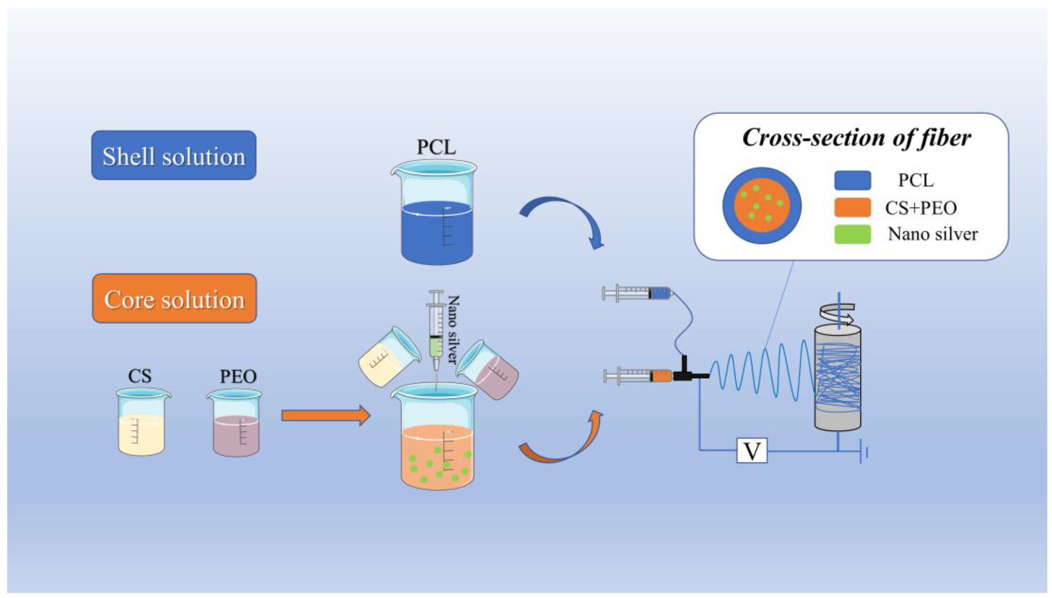
2.1. Materials for Preparation of Coaxial Electrospun Membrane
2.2. Analysis of Key Process Parameters of Coaxial Electrospinning
2.3. Orthogonal Experimental Analysis
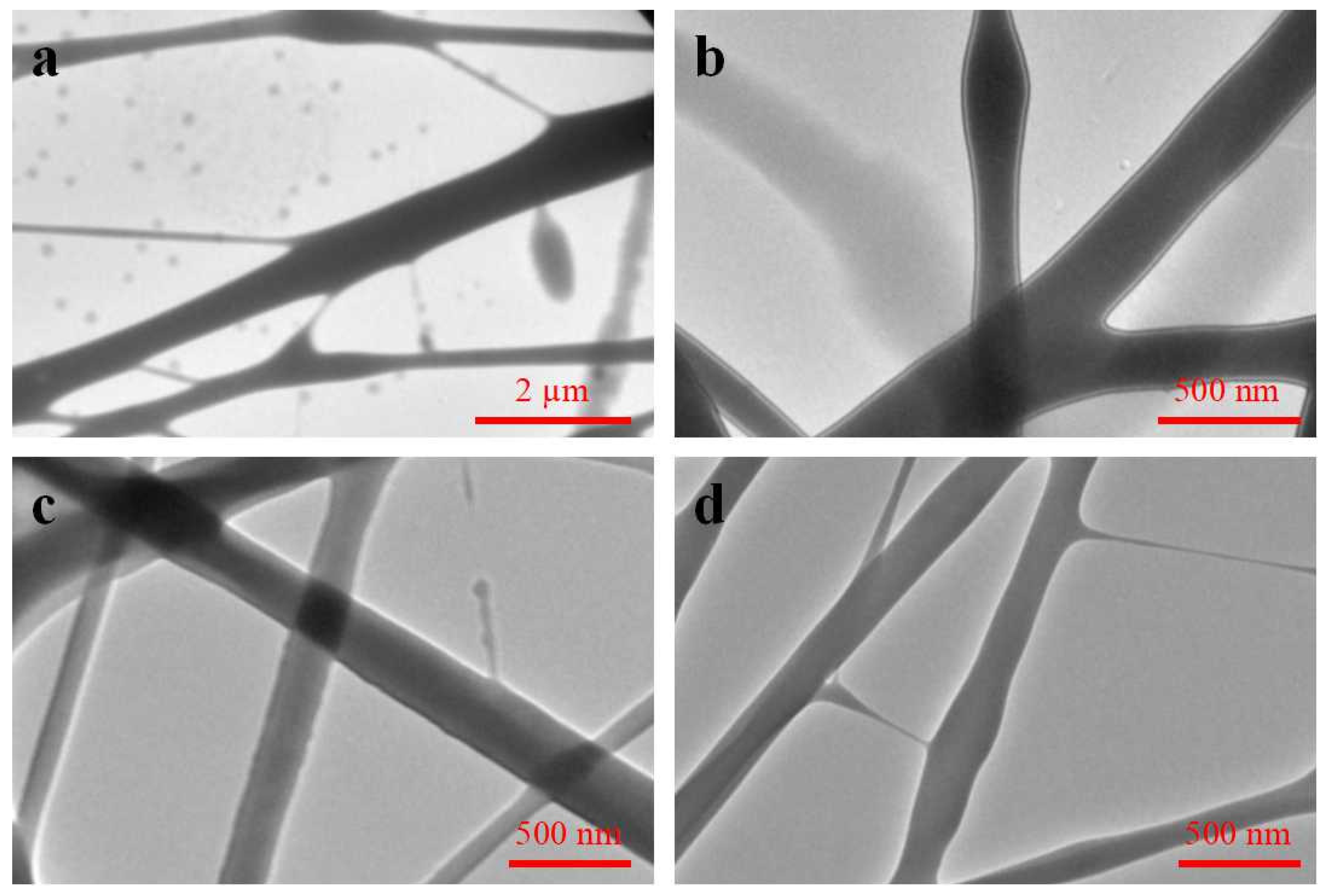
2.4. Microscopic Characterization of Coaxial Electrospun Membrane
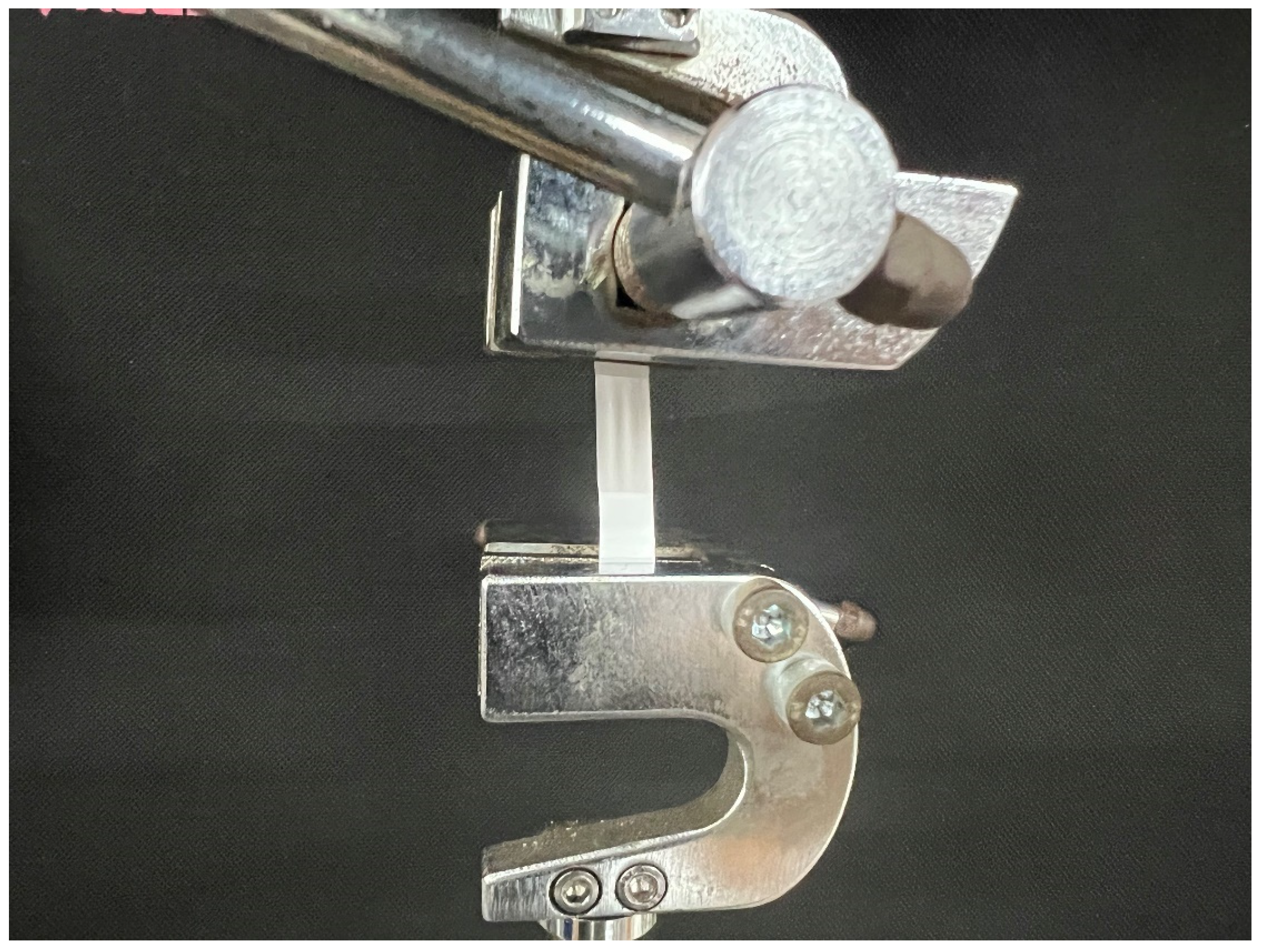
2.5. Test of Tensile Strength
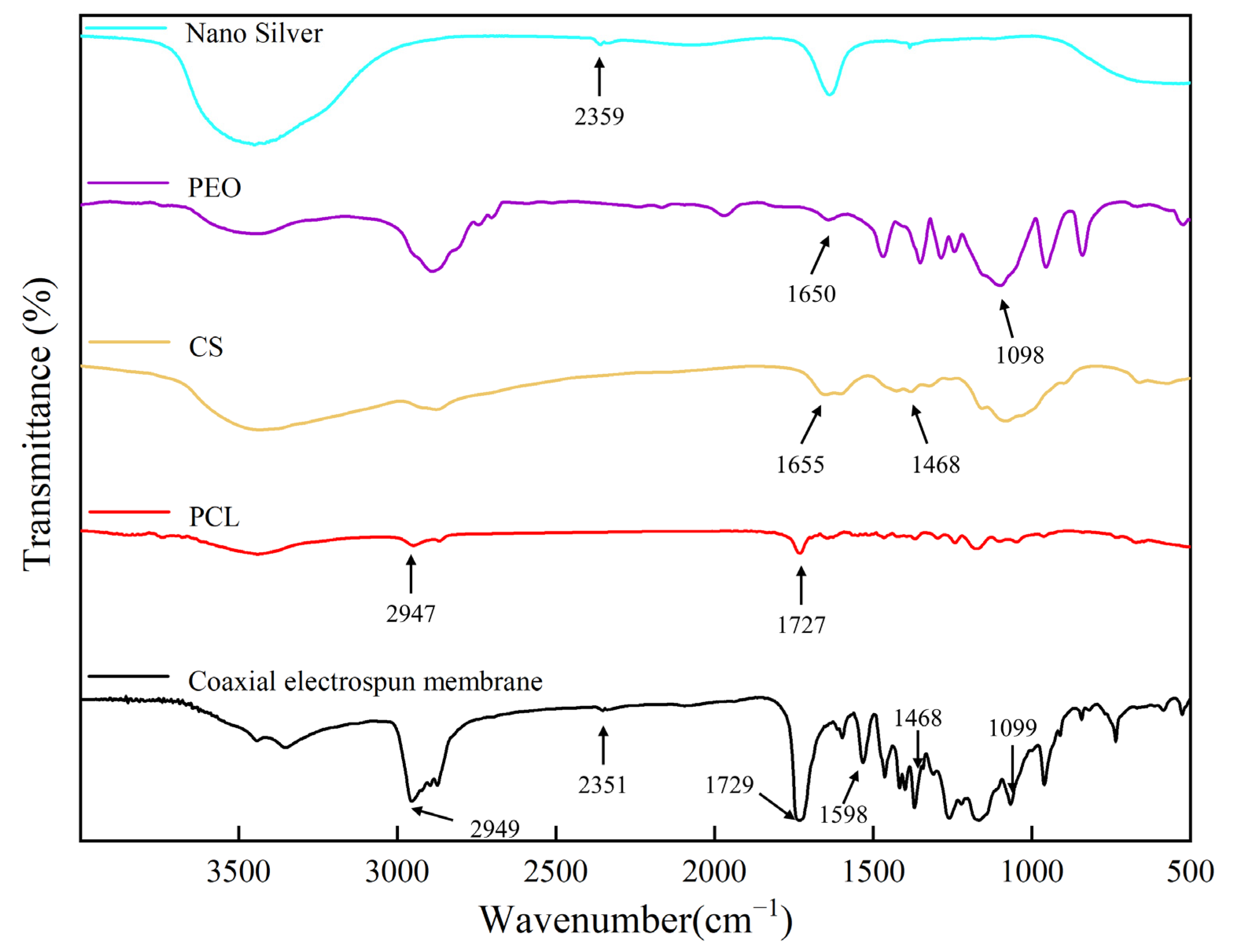
2.6. Fourier Transform Infrared Spectrometry (FTIR) Analysis
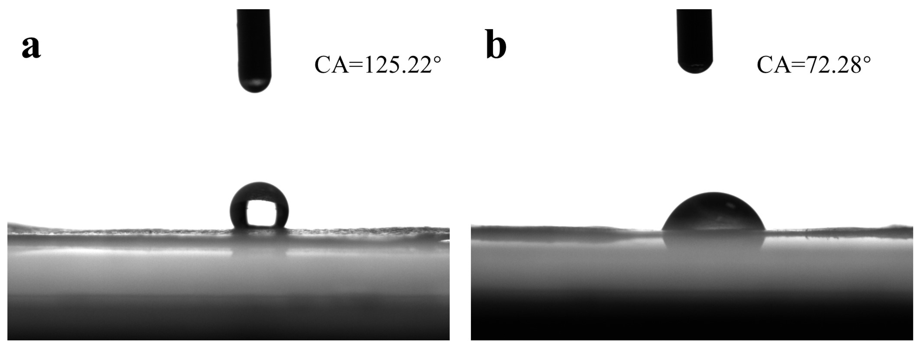
2.7. Test of Hydrophilicity
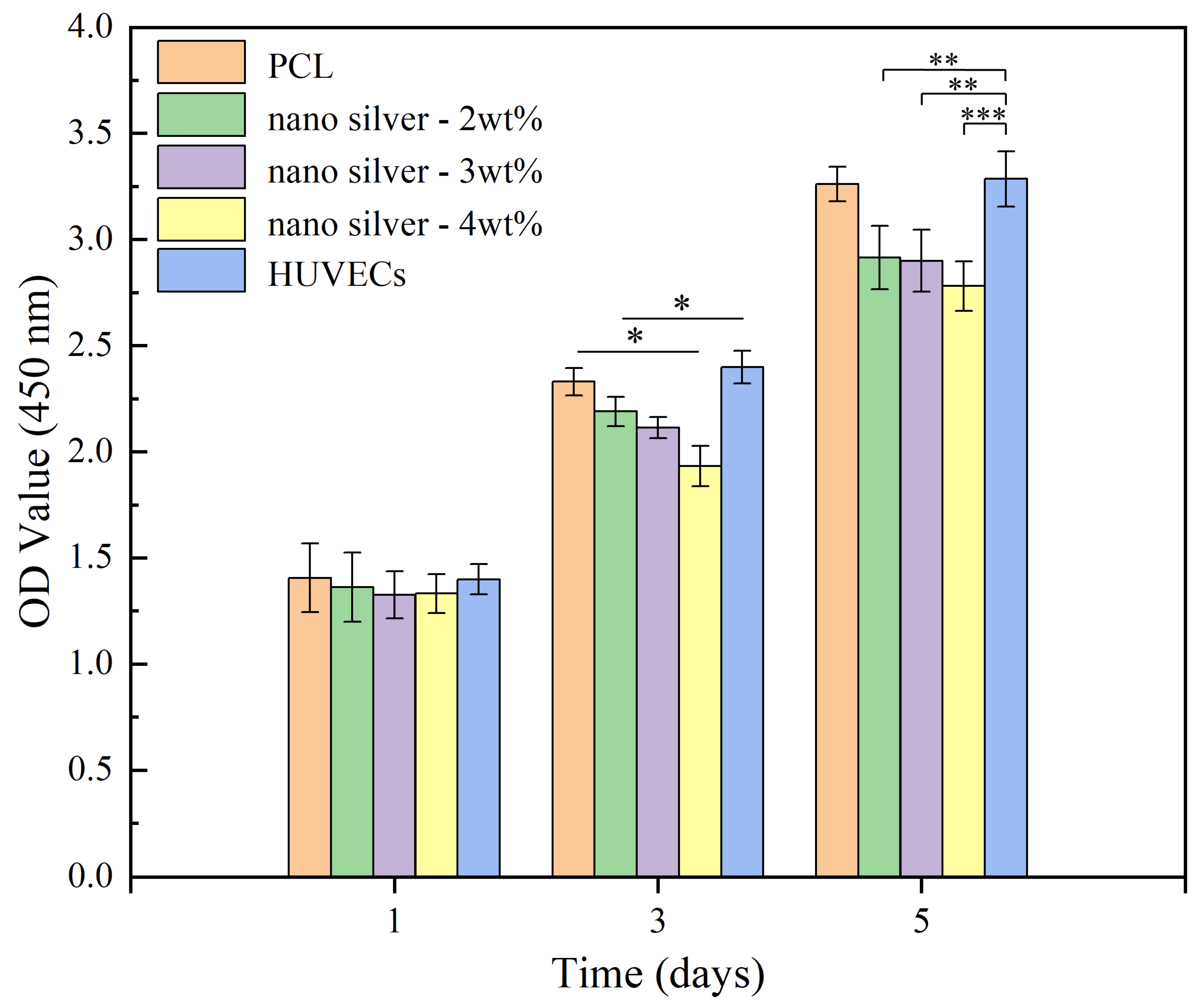
2.8. Test of Cell Cytotoxicity
2.9. Test of Cell Adhesion
2.10. Test of Bacteriostatic Performance
3. Results and Discussion
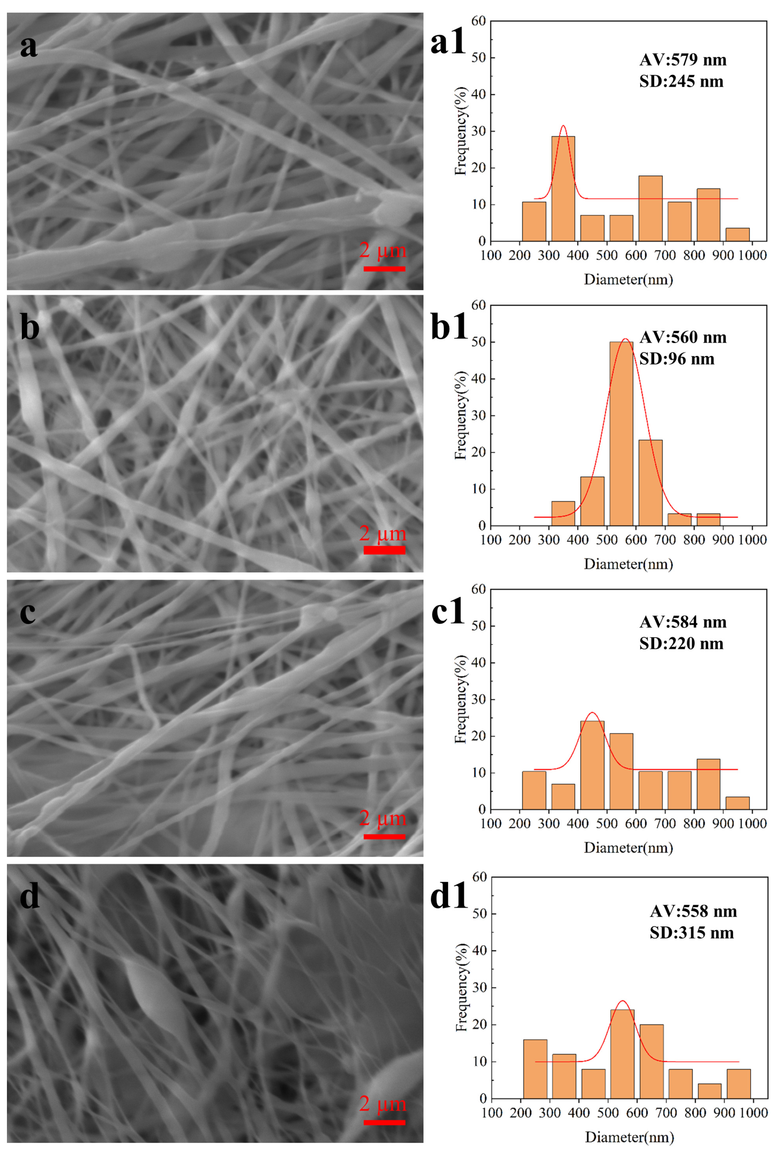
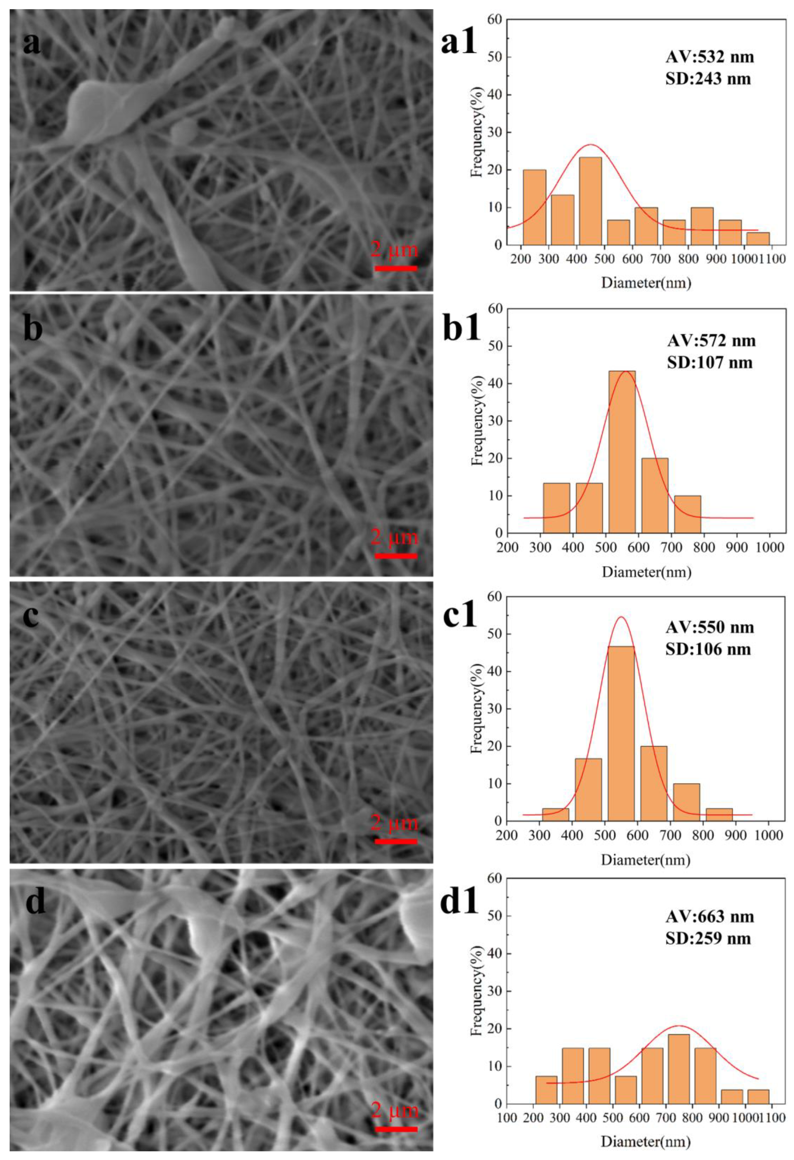
3.1. Influence of Key Process Parameters of Coaxial Electrospinning on Membrane
3.2. Analysis of Orthogonal Test Results
3.3. Fourier Transform Infrared Spectrometry (FTIR)
3.4. Hydrophilicity
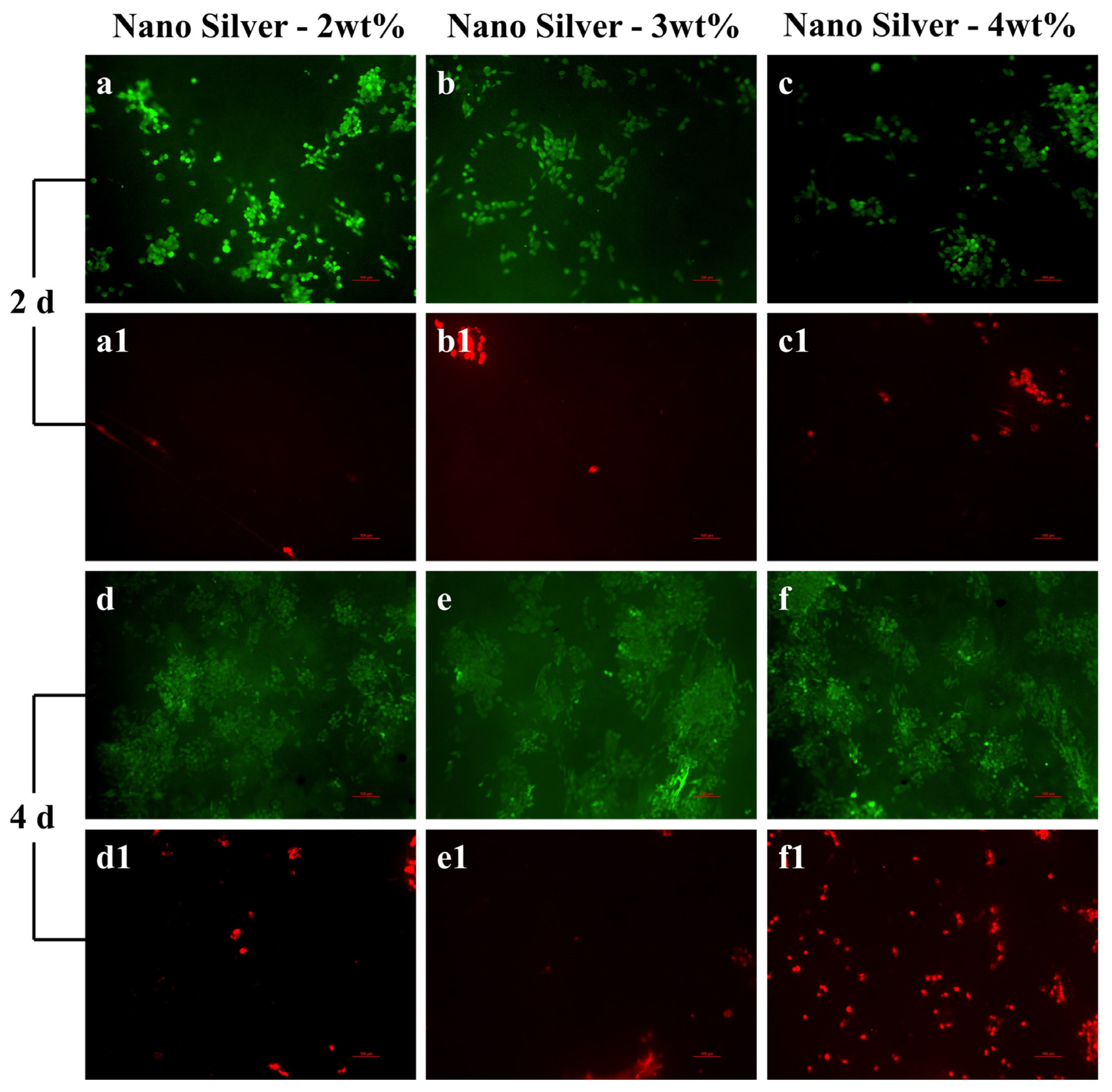
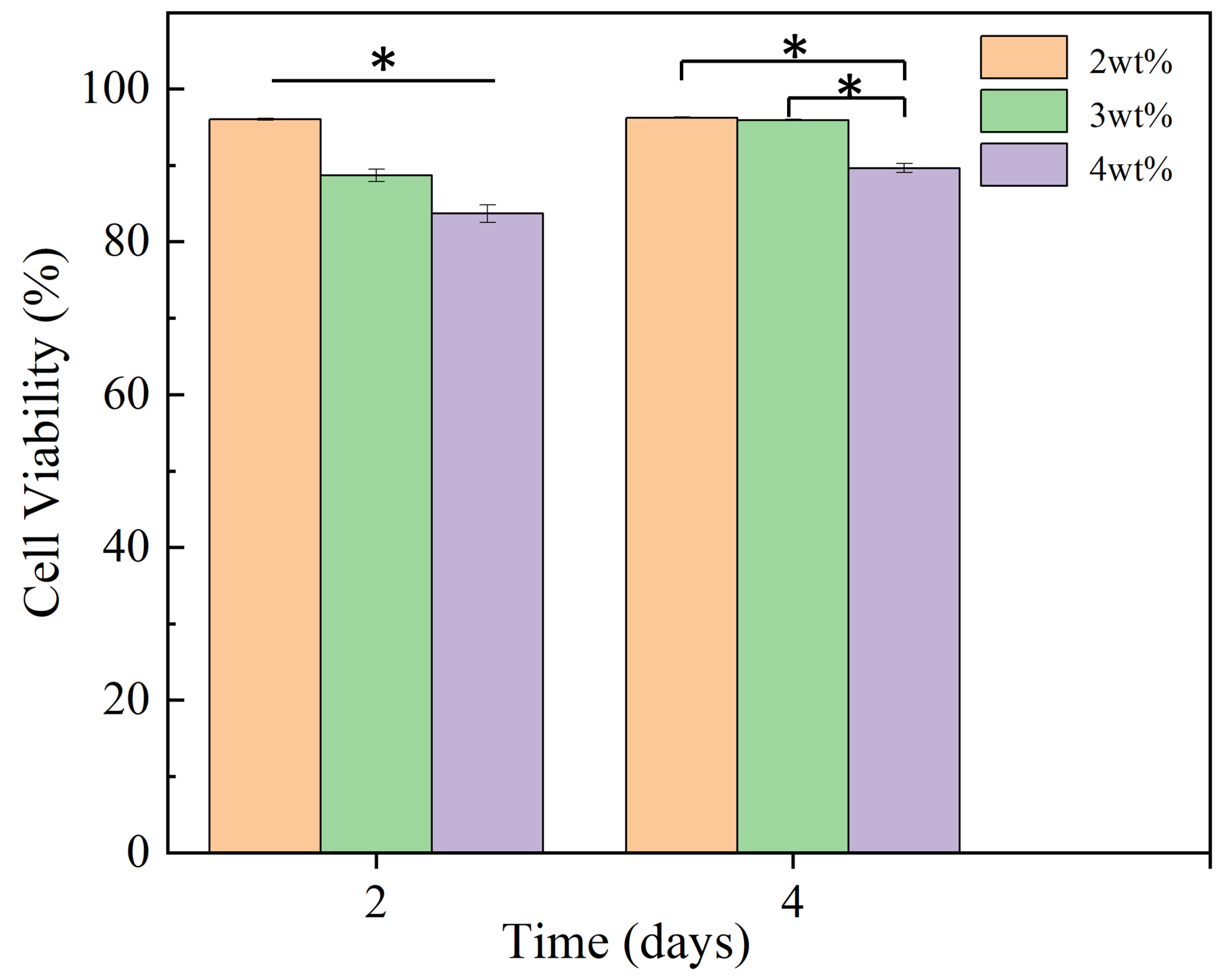
3.5. Cytotoxicity
3.6. Cell Adhesion
3.7. Bacteriostatic Performance
4. Conclusions
Author Contributions
Funding
Institutional Review Board Statement
Data Availability Statement
Conflicts of Interest
References
- Pant, B.; Park, M.; Park, S.J. Drug Delivery Applications of Core-Sheath Nanofibers Prepared by Coaxial Electrospinning: A Review. Pharmaceutics 2019, 11, 305. [Google Scholar] [CrossRef] [PubMed]
- Yang, Q.; Guo, J.; Zhang, S.; Guan, F.C.; Yu, Y.; Yao, Q.; Zhang, X.; Xu, Y. PVA/PEO/PVA-g-APEG nanofiber membranes with cytocompatibility and anti-cell adhesion for biomedical applications. Colloid Surf. A-Physicochem. Eng. Asp. 2023, 657, 130638. [Google Scholar] [CrossRef]
- Wang, Z.H.; Liu, C.G.; Zhu, D.; Gu, X.; Xu, Y.; Qin, Q.H.; Dong, N.G.; Zhang, S.M.; Wang, J.L. Untangling the co-effects of oriented nanotopography and sustained anticoagulation in a biomimetic intima on neovessel remodeling. Biomaterials 2020, 231, 119654. [Google Scholar] [CrossRef]
- Diaz, J.E.; Barrero, A.; Marquez, M.; Loscertales, I.G. Controlled encapsulation of hydrophobic liquids in hydrophilic polymer nanofibers by co-electrospinning. Adv. Funct. Mater. 2006, 16, 2110–2116. [Google Scholar] [CrossRef]
- Katsogiannis, K.A.G.; Vladisavljević, G.T.; Georgiadou, S. Porous electrospun polycaprolactone fibers: Effect of process parameters. J. Polym. Sci. Part B Polym. Phys. 2016, 54, 1878–1888. [Google Scholar] [CrossRef]
- Li, M.; Zheng, Y.; Xin, B.; Xu, Y. Coaxial Electrospinning: Jet Motion, Core–Shell Fiber Morphology, and Structure as a Function of Material Parameters. Ind. Eng. Chem. Res. 2020, 59, 6301–6308. [Google Scholar] [CrossRef]
- de Luca, A.C.; Stevens, J.S.; Schroeder, S.L.M.; Guilbaud, J.B.; Saiani, A.; Downes, S.; Terenghi, G. Immobilization of cell-binding peptides on poly-e-caprolactone film surface to biomimic the peripheral nervous system. J. Biomed. Mater. Res. Part A 2013, 101, 491–501. [Google Scholar] [CrossRef]
- Ozkan, O.; Sasmazel, H.T. Effects of nozzle type atmospheric dry air plasma on L929 fibroblast cells hybrid poly (epsilon-caprolactone)/chitosan/poly (epsilon-caprolactone) scaffolds interactions. J. Biosci. Bioeng. 2016, 122, 232–239. [Google Scholar] [CrossRef]
- Zhang, Y.; Xu, K.; Zhi, D.K.; Qian, M.Y.; Liu, K.Z.; Shuai, Q.Z.; Qin, Z.; Xie, J.H.; Wang, K.; Yang, J. Improving Vascular Regeneration Performance of Electrospun Poly(epsilon-Caprolactone) Vascular Grafts via Synergistic Functionalization with VE-Cadherin/VEGF. Adv. Fiber Mater. 2022, 4, 1685–1702. [Google Scholar] [CrossRef]
- Surucu, S.; Turkoglu Sasmazel, H. Development of core-shell coaxially electrospun composite PCL/chitosan scaffolds. Int. J. Biol. Macromol. 2016, 92, 321–328. [Google Scholar] [CrossRef]
- Gupta, D.; Venugopal, J.; Prabhakaran, M.P.; Dev, V.R.G.; Low, S.; Choon, A.T.; Ramakrishna, S. Aligned and random nanofibrous substrate for the in vitro culture of Schwann cells for neural tissue engineering. Acta Biomater. 2009, 5, 2560–2569. [Google Scholar] [CrossRef] [PubMed]
- Dutta, P.K.; Ravikumar, M.N.; Dutta, J. Chitin and chitosan for versatile applications. J. Macromol. Sci. Part C-Polym. Rev 2002, 42, 307–354. [Google Scholar] [CrossRef]
- Shalumon, K.T.; Anulekha, K.H.; Girish, C.M.; Prasanth, R.; Nair, S.V.; Jayakumar, R. Single step electrospinning of chitosan/poly(caprolactone) nanofibers using formic acid/acetone solvent mixture. Carbohydr. Polym. 2010, 80, 413–419. [Google Scholar] [CrossRef]
- Di Martino, A.; Sittinger, M.; Risbud, M.V. Chitosan: A versatile biopolymer for orthopaedic tissue-engineering. Biomaterials 2005, 26, 5983–5990. [Google Scholar] [CrossRef]
- Song, Q.Q.; Wu, W.W.; Wang, Y.; Yu, J.R.; Hu, Z.M.; Wang, Y. The Structure and Properties of Polyethylene Oxide Reinforced Poly(Metaphenylene Isophthalamide) Fibers. Adv. Fiber Mater. 2022, 4, 436–447. [Google Scholar] [CrossRef]
- Shan, B.; Cai, Y.Z.; Brooks, J.D.; Corke, H. Antibacterial properties of Polygonum cuspidatum roots and their major bioactive constituents. Food Chem. 2008, 109, 530–537. [Google Scholar] [CrossRef]
- Alt, V.; Bechert, T.; Steinrucke, P.; Wagener, M.; Seidel, P.; Dingeldein, E.; Domann, E.; Schnettler, R. An in vitro assessment of the antibacterial properties and cytotoxicity of nanoparticulate silver bone cement. Biomaterials 2004, 25, 4383–4391. [Google Scholar] [CrossRef]
- Chaloupka, K.; Malam, Y.; Seifalian, A.M. Nanosilver as a new generation of nanoproduct in biomedical applications. Trends Biotechnol. 2010, 28, 580–588. [Google Scholar] [CrossRef]
- Akmaz, S.; Dilaver Adıgüzel, E.; Yasar, M.; Erguven, O. The Effect of Ag Content of the Chitosan-Silver Nanoparticle Composite Material on the Structure and Antibacterial Activity. Adv. Mater. Sci. Eng. 2013, 2013, 690918. [Google Scholar] [CrossRef]
- Li, Y.; Shi, Y.; Lu, Y.; Li, X.; Zhou, J.; Zadpoor, A.A.; Wang, L. Additive manufacturing of vascular stents. Acta Biomater. 2023, 167, 16–37. [Google Scholar] [CrossRef]
- Bosman, W.M.; Borger van der Burg, B.L.; Schuttevaer, H.M.; Thoma, S.; Hedeman Joosten, P.P. Infections of intravascular bare metal stents: A case report and review of literature. Eur. J. Vasc. Endovasc. Surg. 2014, 47, 87–99. [Google Scholar] [CrossRef] [PubMed]
- Han, B.; Wang, X.; Zheng, J.; Liang, S.; Xiao, K.; Yu, J.; Qian, Z.; Huang, X. Determination of Surface Energy Parameters of Hydrophilic Porous Membranes via a Corrected Contact Angle Approach. Langmuir 2019, 35, 15009–15016. [Google Scholar] [CrossRef] [PubMed]
- Cai, L.; Qin, X.; Xu, Z.; Song, Y.; Jiang, H.; Wu, Y.; Ruan, H.; Chen, J. Comparison of Cytotoxicity Evaluation of Anticancer Drugs between Real-Time Cell Analysis and CCK-8 Method. ACS Omega 2019, 4, 12036–12042. [Google Scholar] [CrossRef] [PubMed]
- Qasim, S.B.; Zafar, M.S.; Najeeb, S.; Khurshid, Z.; Shah, A.H.; Husain, S.; Rehman, I.U. Electrospinning of Chitosan-Based Solutions for Tissue Engineering and Regenerative Medicine. Int. J. Mol. Sci. 2018, 19, 407. [Google Scholar] [CrossRef] [PubMed]
- Ju, J.G.; Shi, Z.J.; Fan, L.L.; Liang, Y.Y.; Kang, W.M.; Cheng, B.W. Preparation of elastomeric tree-like nanofiber membranes using thermoplastic polyurethane by one-step electrospinning. Mater. Lett. 2017, 205, 190–193. [Google Scholar] [CrossRef]
- Ngadiman, N.H.A.; Noordin, M.Y.; Idris, A.; Kurniawan, D. Effect of Electrospinning Parameters Setting Towards Fiber Diameter. In Proceedings of the 1st International Materials, Industrial, and Manufacturing Engineering Conference, Johor Bahru, Malaysia, 4–6 December 2013; Trans Tech Publications Ltd.: Johor Bahru, Malaysia, 2013; pp. 985–988. [Google Scholar]
- Kuntzler, S.G.; Costa, J.A.V.; Morais, M.G. Development of electrospun nanofibers containing chitosan/PEO blend and phenolic compounds with antibacterial activity. Int. J. Biol. Macromol. 2018, 117, 800–806. [Google Scholar] [CrossRef]
- Semnani, D.; Naghashzargar, E.; Hadjianfar, M.; Dehghan Manshadi, F.; Mohammadi, S.; Karbasi, S.; Effaty, F. Evaluation of PCL/chitosan electrospun nanofibers for liver tissue engineering. Int. J. Polym. Mater. Polym. Biomater. 2016, 66, 149–157. [Google Scholar] [CrossRef]
- Kumar, P.T.S.; Abhilash, S.; Manzoor, K.; Nair, S.V.; Tamura, H.; Jayakumar, R. Preparation and characterization of novel β-chitin/nanosilver composite scaffolds for wound dressing applications. Carbohydr. Polym. 2010, 80, 761–767. [Google Scholar] [CrossRef]
- Corin, C.; Sutherland, G.B.B.M. The infra-red absorption spectrum of methylene chloride. Proc. R. Soc. London Ser. A Math. Phys. Sci. 1997, 165, 43–53. [Google Scholar] [CrossRef]
- Biliškov, N.; Baranović, G. Infrared spectroscopy of liquid water–N,N-dimethylformamide mixtures. J. Mol. Liq. 2009, 144, 155–162. [Google Scholar] [CrossRef]
- Sendner, C.; Horinek, D.; Bocquet, L.; Netz, R.R. Interfacial Water at Hydrophobic and Hydrophilic Surfaces: Slip, Viscosity, and Diffusion. Langmuir 2009, 25, 10768–10781. [Google Scholar] [CrossRef] [PubMed]
- Lim, F.; Cooper, S.L. Effect of sulphonate incorporation on in vitro leucocyte adhesion to polyurethanes. Biomaterials 1995, 16, 457–466. [Google Scholar] [CrossRef] [PubMed]
- Feng, Y.; Jupei, Z.; Dong, Z.; Tang, L. Characterization, biocompatibility, and optimization of electrospun SF/PCL composite nanofiber films. Rev. Adv. Mater. Sci. 2023, 62, 20220333. [Google Scholar] [CrossRef]
- López-Serrano, A.; Olivas, R.M.; Landaluze, J.S.; Cámara, C. Nanoparticles: A global vision. Characterization, separation, and quantification methods. Potential environmental and health impact. Anal. Methods 2014, 6, 38–56. [Google Scholar] [CrossRef]
- Abbaszadegan, A.; Ghahramani, Y.; Gholami, A.; Hemmateenejad, B.; Dorostkar, S.; Nabavizadeh, M.; Sharghi, H. The Effect of Charge at the Surface of Silver Nanoparticles on Antimicrobial Activity against Gram-Positive and Gram-Negative Bacteria: A Preliminary Study. J. Nanomater. 2015, 2015, 720654. [Google Scholar] [CrossRef]
- Song, Y.; Hu, Q.; Liu, Q.; Liu, S.; Wang, Y.; Zhang, H. Design and fabrication of drug-loaded alginate/hydroxyapatite/collagen composite scaffolds for repairing infected bone defects. J. Mater. Sci. 2023, 58, 911–926. [Google Scholar] [CrossRef]
- Rade, P.P.; Giram, P.S.; Shitole, A.A.; Sharma, N.; Garnaik, B. Physicochemical and in Vitro Antibacterial Evaluation of Metronidazole Loaded Eudragit S-100 Nanofibrous Mats for the Intestinal Drug Delivery. Adv. Fiber Mater. 2022, 4, 76–88. [Google Scholar] [CrossRef]
- Tran, Q.H.; Nguyen, V.Q.; Le, A.T. Silver nanoparticles: Synthesis, properties, toxicology, applications and perspectives. Adv. Nat. Sci. Nanosci. Nanotechnol. 2013, 4, 033001. [Google Scholar] [CrossRef]


| Experimental Group | Factor | Tensile Strength (MPa) | |||
|---|---|---|---|---|---|
| A (w/v) | B (kV) | C (cm) | D (/) | ||
| 1 | 2% (1) | 12 (1) | 14 (1) | 1:2 (1) | 1.720 ± 0.106 |
| 2 | 2% (1) | 14 (2) | 18 (3) | 1:3 (2) | 2.108 ± 0.132 |
| 3 | 2% (1) | 16 (3) | 16 (2) | 1:4 (3) | 2.066 ± 0.143 |
| 4 | 3% (2) | 12 (1) | 18 (3) | 1:4 (3) | 2.672 ± 0.127 |
| 5 | 3% (2) | 14 (2) | 16 (2) | 1:3 (2) | 2.945 ± 0.092 |
| 6 | 3% (2) | 16 (3) | 14 (1) | 1:2 (1) | 2.841 ± 0.071 |
| 7 | 4% (3) | 12 (1) | 16 (2) | 1:3 (2) | 2.066 ± 0.146 |
| 8 | 4% (3) | 14 (2) | 14 (1) | 1:4 (3) | 2.359 ± 0.092 |
| 9 | 4% (3) | 16 (3) | 18 (3) | 1:2 (1) | 1.603 ± 0.084 |
| K1 | 5.894 | 6.458 | 6.92 | 6.164 | |
| K2 | 8.458 | 7.412 | 7.077 | 7.119 | |
| K3 | 6.028 | 6.51 | 6.383 | 7.097 | |
| k1 | 1.965 | 2.153 | 2.307 | 2.055 | |
| k2 | 2.819 | 2.471 | 2.359 | 2.373 | |
| k3 | 2.009 | 2.17 | 2.128 | 2.366 | |
| R | 0.854 | 0.318 | 0.231 | 0.318 | |
| Primary and secondary order | A > B = D > C | ||||
| Optimal combination | A2B2C2D2 | ||||
Disclaimer/Publisher’s Note: The statements, opinions and data contained in all publications are solely those of the individual author(s) and contributor(s) and not of MDPI and/or the editor(s). MDPI and/or the editor(s) disclaim responsibility for any injury to people or property resulting from any ideas, methods, instructions or products referred to in the content. |
© 2023 by the authors. Licensee MDPI, Basel, Switzerland. This article is an open access article distributed under the terms and conditions of the Creative Commons Attribution (CC BY) license (https://creativecommons.org/licenses/by/4.0/).
Share and Cite
Hu, Q.; Huang, Z.; Zhang, H.; Ramalingam, M. Preparation and Characterization of Nano-Silver-Loaded Antibacterial Membrane via Coaxial Electrospinning. Biomimetics 2023, 8, 419. https://doi.org/10.3390/biomimetics8050419
Hu Q, Huang Z, Zhang H, Ramalingam M. Preparation and Characterization of Nano-Silver-Loaded Antibacterial Membrane via Coaxial Electrospinning. Biomimetics. 2023; 8(5):419. https://doi.org/10.3390/biomimetics8050419
Chicago/Turabian StyleHu, Qingxi, Zhenwei Huang, Haiguang Zhang, and Murugan Ramalingam. 2023. "Preparation and Characterization of Nano-Silver-Loaded Antibacterial Membrane via Coaxial Electrospinning" Biomimetics 8, no. 5: 419. https://doi.org/10.3390/biomimetics8050419
APA StyleHu, Q., Huang, Z., Zhang, H., & Ramalingam, M. (2023). Preparation and Characterization of Nano-Silver-Loaded Antibacterial Membrane via Coaxial Electrospinning. Biomimetics, 8(5), 419. https://doi.org/10.3390/biomimetics8050419