Abstract
Bubble columns are widely used in numerous industrial processes because of their advantages in operation, design, and maintenance compared to other multiphase reactor types. In contrast to their simple design, the generated flow conditions inside a bubble column reactor are quite complex, especially in continuous mode with counter-current liquid flow. For the design and optimization of such reactors, precise numerical simulations and modelling are needed. These simulations and models have to be validated with experimental data. For this reason, experiments were carried out in a laboratory-scale bubble column using shadow imaging and particle image velocimetry (PIV) techniques with and without counter-current liquid flow. In the experiments, two types of gases—relatively poorly soluble air and well-soluble CO2—were used and the bubbles were generated with three different capillary diameters. With changing gas and liquid flow rates, overall, 108 different flow conditions were investigated. In addition to the liquid flow fields captured by PIV, shadow imaging data were also statistically evaluated in the measurement volume and bubble parameters such as bubble diameter, velocity, aspect ratio, bubble motion direction, and inclination. The bubble slip velocity was calculated from the measured liquid and bubble velocities. The analysis of these parameters shows that the counter-current liquid flow has a noticeable influence on the bubble parameters, especially on the bubble velocity and motion direction. In the case of CO2 bubbles, remarkable bubble shrinkage was observed with counter-current liquid flow due to the enhanced mass transfer. The results obtained for bubble aspect ratio are compared to known correlations from the literature. The comprehensive and extensive bubble data obtained in this study will now be used as a source for the development of correlations needed in the validation of numerical simulations and models. The data are available from the authors on request.
1. Introduction
Bubble column reactors are simple multiphase contactors where the gas phase is dispersed in the continuous phase. Since they have no moving parts, the operation and maintenance of these reactors is simple. Bubble columns in batch mode are widely used in the chemical, biochemical, and petrochemical industries. However, e.g., in water and wastewater treatment, counter-current flow of liquid and gas is applied to increase the gas holdup, enhance mixing, and increase the bubble residence time and, therefore, mass transfer. As Joshi et al. [1] pointed out, the counter-current liquid flow enhances the liquid phase turbulence which could be beneficial for mixing and mass transfer. For this reason, numerous papers deal with the effect of counter-current operation on global properties like gas holdup [2,3,4,5,6,7,8,9,10,11,12] or mass transfer [2,6,11,12,13] in bubble columns. In these studies, important gas holdups are discussed; therefore, very dense bubbly flows were investigated. Due to the high void fraction, the bubbly flow is then opaque and the application of optical measurement techniques (e.g., shadow imaging) to examine bubble properties like diameter or aspect ratio is very limited. Because of this limitation, shadow imaging has been combined with intrusive measurement techniques, e.g., with fiber probes [4,5,14,15] or with borescope [9]. These combined techniques allow then for the determination of bubble properties like diameter, aspect ratio, velocity, or bubble orientation in dense flow, while, unfortunately, disturbing the flow.
Since for the validation of numerical simulations and models of two-phase reactors and processes the global properties of the reactor are often not sufficient, detailed spatially and temporally resolved experimental data in the undisturbed flow are needed. Therefore, in this study, which is an extended version of a paper initially presented at the 20th International Symposium on the Application of Laser and Imaging Techniques to Fluid Mechanics, 2022, in Lisbon, Portugal [16], we present the results of such bubble parameter data (e.g., shape, motion, size) from bubble swarms rising in a laboratory-scale bubble column. The data were obtained by shadow imaging for a wide range of bubble sizes and operational parameters, with and without counter-current liquid flow. Because of the abovementioned optical accessibility problems, the experiments were carried out at low gas holdups to ensure precise bubble recognition. Shadow imaging combined with PTV (particle tracking velocimetry) was used to initially determine bubble size, shape, and velocity. From these original data, further parameters were derived, as, e.g., bubble aspect ratio, bubble motion direction, and bubble inclination (both not shown in this paper), and their spatial and temporal evolution in the column is thus available. Thanks to the large number of initially acquired images and, thus, individual bubbles, also a statistical evaluation of the aforementioned quantities was possible, not only for the complete column, but also depending on the heights inside the column. Moreover, in addition to the shadow imaging, PIV measurements were also carried out to gain information about the liquid flow. These liquid velocity measurements ensure the calculation of the slip velocity of the bubbles at different flow conditions. These results are exemplarily presented in this paper to give an overview of the content of the complete database, acquired in the context of this study. These data now serve further for the generation and evaluation of correlations and models, or as validation data for numerical codes as, e.g., needed in [17,18,19,20]. The database is also accessible to the interested readers upon request.
2. Initial Experiments
Both measurement methods—shadow imaging and PIV—were executed in a square section laboratory-scale bubble column made of acrylic glass with an inner side length of d = 0.1 m and a height of h = 2 m (Figure 1, #1). A bubble curtain was generated with seven capillaries placed in line in the center of the bubble column (Figure 1, #3), and bubbles in a size range of 1 mm to 9 mm were produced by introducing CO2 or air through capillaries of different diameter (0.13 mm, 0.18 mm, and 3.6 mm). Gas flow rates from 1.3 l·h−1 up to 48 l·h−1 (2.4 g·h−1 to 57.5 g·h−1 mass flow rate; 3.6 × 10⁻⁵ m·s−1 to 1.3 × 10⁻³ m·s−1 superficial gas velocity) were investigated in stagnant liquid and under five different counter-current liquid flow conditions (see Table 1, and [16]). For every experiment, the water was prepared with a water softening system and with an ion exchanger to ensure that its conductivity lied below 30 µS/cm. Degassing of the water was not carried out, since unwanted dissolution of gases in the open experimental facility could not be avoided. Nevertheless, preliminary results from long-term experiments have shown that the dissolution of air or CO2 is not a problem. The rates are very small compared to mass transfer from the bubbles. The saturation level was not reached during the experiments.
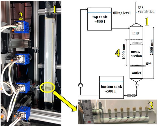
Figure 1.
Experimental setup.

Table 1.
Investigated cases.
The images were recorded with four 5 Mpixel sCMOS cameras (Imager sCMOS, LaVision, Göttingen, Germany) (Figure 1, #2) equipped with 50 mm Nikon Micro lenses to simultaneously record images over the entire measurement section (1 m) of the column (Figure 1, #4). The cameras were focused on the center of the column. Eight high-power LEDs were attached together with a sheet of thin drawing paper as a light diffusor on the back wall of the column to obtain a homogeneous light distribution for the shadow imaging, while the rhodamine B doped tracer particles (1–20 μm) for the PIV measurements were illuminated with two laser (532 nm Nd:YAG) light sheets placed above each other to illuminate the whole investigated section. In the case of shadow imaging, the bubbles in a 33 mm thick volume in the center of the column, where most bubbles remain during their rise, were evaluated. The bubbles beyond this depth of field were unfocused and not taken into account. The geometrical calibration was performed in the whole measurement area with a half meter long three-dimensional calibration plate. The obtained mean calibration error of the images with 1300 × 2600 pixels was below 0.8 pixel. The resolution of the images was 0.105 mm/pixel, which leads to an uncertainty of 1.2% to 10.5% for the 9 mm and 1 mm bubbles, respectively, for single bubble recognition.
With this experimental setup, 4000 pictures were taken with an 80 Hz recording rate for the shadow imaging and a 5 Hz recording rate (double frame) for the PIV measurements for each investigated case.
The experiments were carried out at three different gas flow rates for air and CO2. Considering also the three capillary diameters and the six liquid flow conditions, 108 different cases were investigated (Table 1). The maximum gas fraction obtained with these conditions was around 0.3%. This low gas content allows for the proper identification of gas bubbles, and bubble break-up or coalescence are avoided. Thus, all identified bubbles originated from the capillary nozzles.
Some impressions on the obtained bubbly flow are given in the following Figure 2 for air and Figure 3 for CO2 bubbles at the lowest and highest counter-current liquid flow rates. The images were obtained in addition to 1000 individual bubble shadow images from the lowest two camera positions as a front view (left), from which the quantitative measurements were taken, and as a side view (right) to show the depth of the bubbly flow.
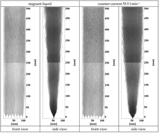
Figure 2.
Bubbly flow field in the bottom half of the column for 6.0 l·h−1 air bubbles generated from 0.13 mm capillaries: without counter-current (left image pair) and with the highest counter-current liquid flow rate (right image pair). The measurement direction (front view) is on the left and the side view on the right of each image pair.
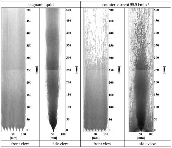
Figure 3.
Bubbly flow fields in the bottom half of the column for 6.6 l·h−1 CO2 bubbles generated from 0.13 mm capillaries: without counter-current (left image pair) and with the highest counter-current liquid flow rate (right image pair). The measurement direction (front view) is on the left and the side view on the right of each image pair.
It is obvious from these images that the counter-current liquid flow rate has a tremendous influence on the bubble trajectories, especially in the case of CO2 bubbles. They were more concentrated in the bottom of the column and only a small number of bubbles could rise further in the column. They were also pushed more to the column front and back walls, thus outside the region of interest for the measurements in the central third of the column depth. The front views (left of each image pair) show the regular distribution of the bubbles over the column width, with most bubbles touching also the walls of the column. Due to the in-line arrangement of the nozzles, the bubbles rarely touched the front and back walls, a phenomenon which can be seen on the side view images (right of each image pair) where the bubbles are concentrated in the central third of the column which corresponds to the measurement volume. Only in the cases with a high counter-current liquid flow rate, and especially for the CO2 bubbles, the very tiny bubbles were pushed to the walls, as already mentioned above. Therefore, the flow can be considered to be, in most cases, a non-wall-bounded bubbly flow.
3. Data Processing
3.1. Shadow Imaging
The recorded shadow images were processed in DaVis 8.4 (LaVision) with a built-in shadow image processing tool combined with a particle tracking velocimetry (PTV) algorithm. The detailed image processing steps can be found in [21]. By employing the distinct intensity gradients at the border of the focused and unfocused bubbles, only those bubbles which were situated in the focused central third of the column volume were recognized. Additional filtering removed bubbles where no bubble velocity could be determined as well as erroneously recognized bubbles (e.g., overlapping bubbles, one big bubble recognized as a bubble cluster, etc.). From the processed data, equivalent sphere diameters (ESD), bubble velocities, and their distributions were obtained, as shown in the examples in Figure 4.

Figure 4.
Global mean bubble ESD (a) and bubble velocity (b) distributions at different counter-current liquid flow conditions and 10 l·h−1 air flow rate from 0.18 mm diameter capillaries.
These data were evaluated further to get information about bubble aspect ratio E, with , bubble inclination β, and bubble velocity direction γ (see Figure 5, the last two are not shown in this paper).
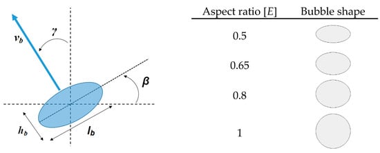
Figure 5.
Bubble parameters evaluated in this study and bubble shapes corresponding to the exemplified aspect ratios.
For the statistical evaluations presented as an overview in this paper, the extensive bubble data were further reduced. Mean values were calculated for each investigated parameter over the width of the column along the column height. These data series are compared in the following sections for equivalent mass flow rates of the two gases. Moreover, bubbles with the same equivalent sphere diameter do not necessarily have the same aspect ratios (see Figure 6). By applying the postprocessing procedure described in detail in [22], mean aspect ratios were calculated for each equivalent sphere diameter (yellow circles in Figure 6). This reduced dataset was then used for further calculations and comparisons.
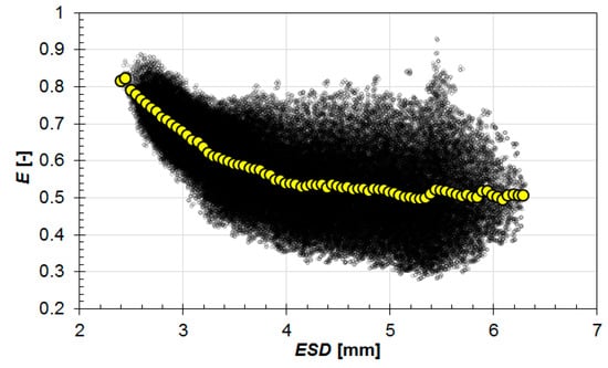
Figure 6.
Exemplary relationship between bubble aspect ratio E and the equivalent sphere diameter ESD at a 6.4 l·h−1 CO2 flow rate, 11.1 l·min−1 counter-current liquid flow, and 3.6 mm capillary diameter. Yellow circles represent the mean aspect ratio.
3.2. Liquid Velocity with PIV
The recorded PIV double-frame images (11 ms interframe delay) were also processed in DaVis 8.4 (LaVision) with a built-in PIV cross-correlation algorithm. For the cross-correlation (multi-pass, decreasing size), an interrogation window size from 64 × 64 pixels to 32 × 32 pixels, with 50% overlap, was used. To remove false vectors and refine the vector field, especially in the vicinity and in the shadows of the bubbles, a median filter was applied. The instantaneous vector fields, processed like this, were averaged in time, and the resulting mean flow fields are used in the following discussion. The average uncertainty of the liquid velocity measurements, estimated according to [23], from each individual PIV vector calculation was, at most, 5% of the mean velocity, depending on the case.
4. Evaluation Results
4.1. Equivalent Sphere Diameter (ESD)
The ESD results for the relatively badly soluble air and well-soluble CO2 bubbles show a very different behavior. An overview of the changes in the ESD of air bubbles is presented in Figure 7. Here, and in all following figures, the legend first displays the capillary diameter, then the gas flow rate is referred to as “g”, and the liquid flow rate as “l”. As expected, with larger capillary diameters, larger bubbles were generated at the same gas and liquid volume flow rate (Figure 7a). The bubble diameters remained almost the same over the column height; just a slight growth of around 0.1 mm could be recognized in the investigated length (1 m). This bubble growth is more visible in Figure 7b–d due to the changed scales and was induced by the decrease in the hydrostatic pressure inside the column.
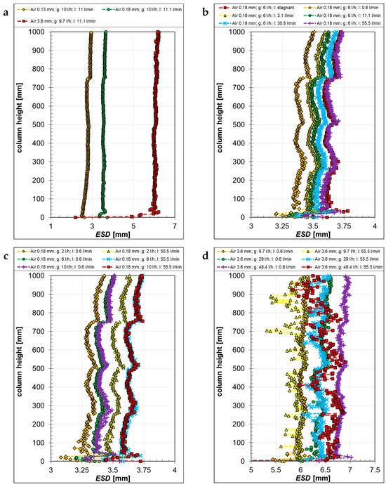
Figure 7.
Equivalent sphere diameter ESD of air bubbles as a function of the column height, generated with different capillaries (a) at different liquid “l” (b) and gas “g” volume flow rates (c,d).
With increasing counter-current liquid flow, the bubble size became bigger (Figure 7b) along the complete column height. It is noticeable that, in the case of stagnant liquid, similar bubble sizes as those recorded at the highest 55.5 l·min−1 counter-current liquid flow rate were found. This similarity was not observed with the 3.6 mm and 0.13 mm capillaries. This suggests that the bubble-forming mechanism at the nozzles was not the same due to different materials being used (here Teflon, see Table 1), thus exerting surface tension effects.
The influence of the gas volume flow rate is represented in Figure 7c,d at two different counter-current liquid flow rates and for two different capillary sizes. With an increasing gas flow rate, the bubble size increased, but the difference between the 6 l·h−1 and 10 l·h−1 gas flow rates was negligible for the 0.18 mm capillary. Also, a higher counter-current liquid flow rate led to bigger bubbles (Figure 7c) for this small capillary size. For the biggest 3.6 mm capillaries, bubble sizes were not affected by the counter-current liquid flow rate in most of the cases, as only an influence of the gas flow rate was observable (Figure 7d). However, large fluctuations in bubble size were visible at the highest counter-current liquid flow rate, especially in the top half of the investigated area.
In contrast to the air bubbles, at the same gas mass flow rates, the CO2 bubbles showed a very different behavior (Figure 8). With an increasing capillary size, the generated bubble size increased also, but, due to the high solubility in water, it decreased continuously along the column height (Figure 8a). The experiments show that the bubbles reached a minimum size of about 1 mm and then they stopped shrinking further (Figure 8a). Probably, all CO2 was dissolved from these bubbles into the liquid and the remaining bubbles consisted of less soluble and back-diffused inert gases, as already known from the literature [24,25]. Slightly below this size, the automatic bubble recognition reached its minimum, because the shadows of these small bubbles were almost as bright as the background. Therefore, reliable bubble recognition was not possible for ESD ≤ 1 mm, and the representation in Figure 8 is, therefore, interrupted (Figure 8a, yellow diamonds).
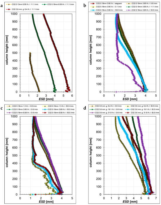
Figure 8.
Equivalent sphere diameter ESD of CO2 bubbles as a function of the column height, generated with different capillaries (a) at different liquid “l” (b) and gas “g” volume flow rates (c,d).
Similarly to the air bubbles, the CO2 bubbles were influenced by the counter-current flow (Figure 8b). Here, however, with an increasing counter-current liquid flow rate, the bubble size became smaller over the column height, while starting with nearly the same bubble diameter at the capillary outlets. The bubble shrinkage gradually increased with increasing counter-current liquid flow rates. The bubble residence time increased, further favoring CO2 dissolution. Also, the liquid renewal on the bubble surfaces became faster with increasing liquid flow rates, enhancing the mass transfer from the bubbles to the liquid.
The influence of the gas flow rate on the generated bubble size is depicted for two different counter-current liquid flows in Figure 8c. With an increasing gas flow rate, the bubble size increased and gradually decreased to about 1 mm along the height of the column. At higher counter-current liquid flow rates, the bubble shrinkage became more significant, as the bubbles reached much earlier the diameter of about 1 mm. In this plot, and also in Figure 8a, it is observable that bubble shrinkage occurred in a parallel way for the same counter-current flow conditions. For this reason, it can be assumed that the mass transfer from the bubbles to the liquid does not only depend on the initial bubble size, but also, essentially, on the counter-current flow conditions. With the 3.6 mm capillaries (Figure 8d), an increasing gas flow rate led to bigger bubble sizes at the bottom of the column. Since bubble shrinkage was less pronounced with the lower liquid flow rate, bubble sizes were bigger at the column top compared to the high liquid counter-current flow for the same gas flow rate.
4.2. Bubble Velocity
In the following paragraphs, the measured bubble velocities will be analyzed. Figure 9 shows the air bubble velocities under different flow conditions, with Figure 9a representing the velocities of the bubbles generated with different capillaries. They differed significantly just above the gas outlets, where the larger bubbles had lower velocities than the smaller ones. After about half the measurement section, all bubbles reached the same mean terminal velocity of about 0.27 m·s−1. With increasing counter-current liquid flow rates, the bubble velocity decreased, but the velocity difference between the two smallest liquid flows and the stagnant condition was negligible (Figure 9b), corresponding to the bubble terminal velocity given by different well-known correlations [26,27]. Also, the influence of the gas flow rate on the bubbles generated by smaller capillaries was negligible at low counter-current liquid flow rates (Figure 9c), while, at the maximum counter-current liquid flow rate, the velocity of the bubbles in the lower part of the column was bigger for higher gas flow rates, until reaching similar terminal velocities at about half the column height. Due to the higher gas flow rate differences with the 3.6 mm capillaries (Figure 9d), the velocities of the bubbles differed more for the three flow conditions shown. With increasing gas flow rates, the bubble velocity increased for all counter-current liquid flow rates, but remained smaller for the higher counter-current flow.
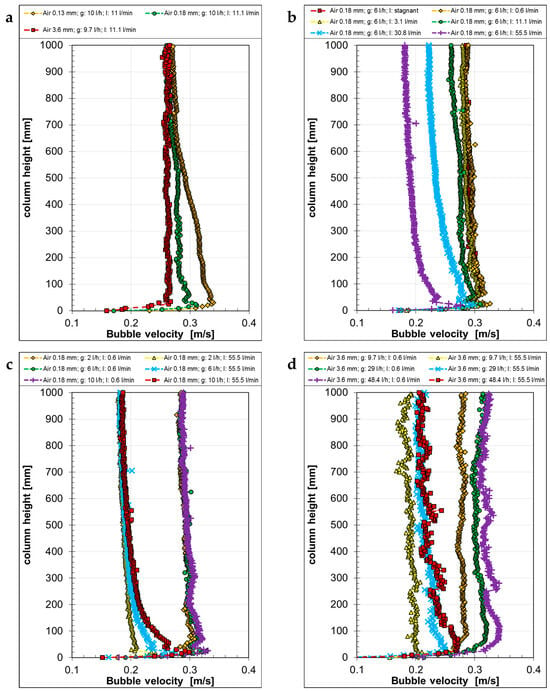
Figure 9.
Bubble velocity of air bubbles as a function of the column height, generated with different capillaries (a) at different liquid “l” (b) and gas “g” volume flow rates (c,d).
At the same gas mass flow rates, the velocities of the CO2 bubbles showed larger differences (Figure 10) due to the stronger size change of the bubbles. With increasing capillary sizes, the bubbles starting velocities decreased. Then, according to bubble shrinkage, the bubble velocities decreased differently along the column height (Figure 10a). When increasing the counter-current liquid flow rate, the bubble velocity decreased along the complete column height (Figure 10b), while increasing gas flow rate increased the velocity for all counter-current liquid flow rates (Figure 10c,d). The velocity of rounder bubbles (aspect ratio E > 0.8, see Figure 12) decreased more strongly (Figure 10c,d, highest counter-current liquid flow rate), while the velocity of the larger bubbles with a lower aspect ratio remained almost the same along the investigated height (Figure 10d, orange, green, and purple symbols).
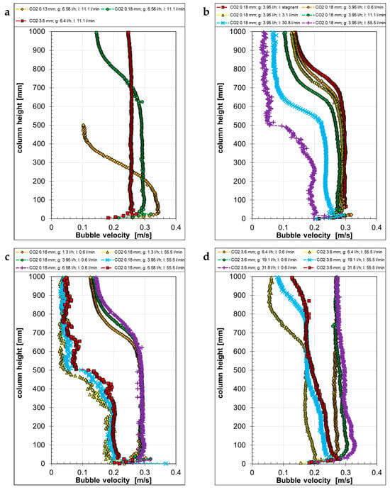
Figure 10.
Bubble velocity of CO2 bubbles as a function of the column height, generated with different capillaries (a) at different liquid “l” (b) and gas “g” volume flow rates (c,d).
4.3. Aspect Ratio (E)
In the following two figures (Figure 11 and Figure 12), the bubble aspect ratio is plotted along the column height under different flow conditions but equivalent gas mass flow rates for air and CO2, respectively. In the case of air bubbles, the aspect ratio of the smallest bubbles generated by the 0.13 mm capillaries increased from the bottom to the top, while it remained almost the same for the two other capillary sizes (Figure 11a). After the bubbles had left the capillaries, the hydrostatic pressure gradually decreased and had a visible influence on the aspect ratio of the small bubbles. It is worth pointing out that neither the counter-current liquid flow rate (Figure 11b) nor the gas flow rate (Figure 11c) influenced significantly the aspect ratio of the bubbles. Only for the largest bubbles at the highest liquid counter-current flow rate a difference was observable (Figure 11d, yellow, blue, and red symbols).
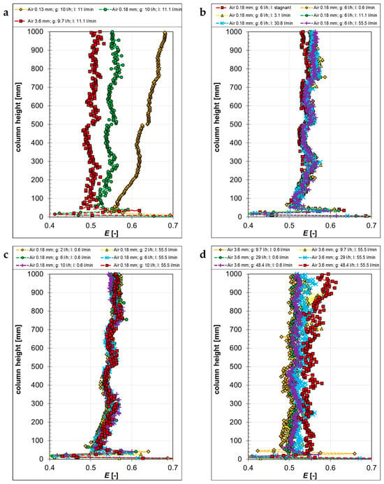
Figure 11.
Aspect ratio E of air bubbles as a function of the column height, generated with different capillaries (a) at different liquid “l” (b) and gas “g” volume flow rates (c,d).
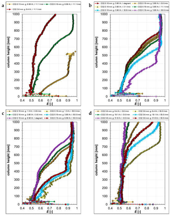
Figure 12.
Aspect ratio E of CO2 bubbles as a function of the column height, generated with different capillaries (a) at different liquid “l” (b) and gas “g” volume flow rates (c,d).
In the case of the CO2 bubbles, the aspect ratio change was dominated by the bubble shrinkage (Figure 12). With decreasing capillary sizes, the aspect ratio increased earlier, due to the initially smaller bubbles (Figure 12a). Since the counter-current liquid flow increased bubble shrinkage, the aspect ratio also increased earlier with higher liquid flow rates (Figure 12b). Also, with increasing gas flow rates, the aspect ratio of the small CO2 bubbles started decreasing directly at the outlet (Figure 12c), while the decrease started later for the bigger bubbles (Figure 12d).
4.4. Liquid Velocity
The general liquid flow behavior in the column is depicted in Figure 13 by streamlines, where air bubbles were generated with the 0.18 mm capillaries at a 10 l·h−1 gas flow rate as an example.
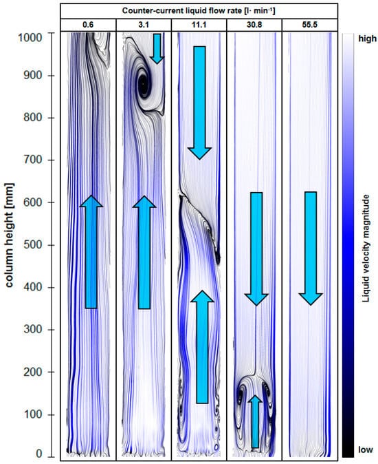
Figure 13.
Streamline visualization of the mean liquid flow structure in the laboratory-scale bubble column at different counter-current liquid flow rates and at a 10 l·h−1 air flow rate with the 0.18 mm capillaries. The bubbles were introduced at the bottom. The arrows indicate the main liquid flow direction.
In this figure, blue arrows indicate the main liquid flow directions. At the lowest counter-current liquid flow rate, the bubble-generated upward flow dominated almost the complete column height. With increasing counter-current liquid flow rates, the stagnation plane between the bubble-generated upward flow and the downward liquid flow moved more and more downwards. At the highest investigated counter-current liquid flow rate, no upward liquid velocity existed anymore. The extent of this effect depends on the gas flow rate and bubble size: the higher the gas flow rate and bubble size, the higher the upward velocity field that exists.
As for the bubble parameters, the vertical liquid flow velocities were averaged over the column width along the column height and are presented for comparison in the following figures. Figure 14 shows the mean vertical liquid velocities for air bubbles under different flow conditions. Significant differences can be found in the liquid velocity between the two small (0.13 mm and 0.18 mm) and the large (3.6 mm) capillaries in Figure 14a. The measured mean vertical liquid velocities for the two smaller capillaries were similar and slightly decreased along the column height, although the bubble size (Figure 7a) and velocity (Figure 9a) differed appreciably. Apparently, here, the gas flow rate was the strongest influencing parameter, and it was the same for both capillaries. In the case of the 3.6 mm capillaries, largely different flow behaviors were observed. The much larger bubbles generated an upward liquid velocity that remained almost constant over the whole investigated height. The velocity also remained always positive (upwards) since, due to their larger surface, drag, and buoyancy, the larger bubbles can mobilize more liquid and generate a stronger upward flow. Moreover, larger velocity fluctuations were found in the case of the larger bubbles.
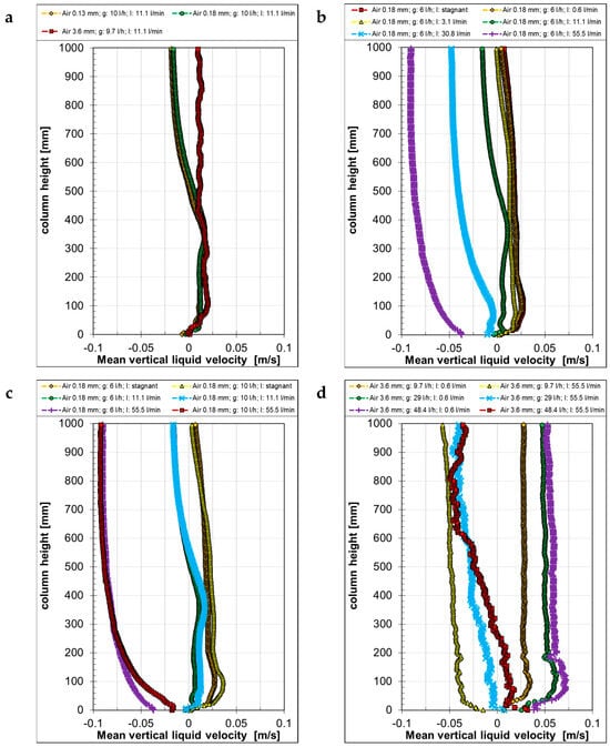
Figure 14.
Mean vertical liquid velocity with air bubbles as a function of the column height, generated with different capillaries (a) at different liquid “l” (b) and gas “g” volume flow rates (c,d).
The effect of the counter-current liquid flow on the bubble-generated upward flow is noticeable in Figure 14b. Depending on the counter-current flow rate, the liquid velocity direction was inverted earlier from positive to negative values. This liquid flow direction change corresponds to that visible in the streamline visualization in Figure 13. In the top 100 mm of the column, the liquid velocity reached that of a potential single-phase flow. The mean vertical liquid velocity profiles for the stagnant case and the case with the lowest counter-current liquid flow rate (0.6 l·min−1) were very similar, except for a slight change in the top region. At a 30.8 l·min−1 counter-current liquid flow rate (blue symbols), the measured vertical liquid velocity became negative all over the investigated height. At the highest counter-current liquid flow rate of 55.5 l·min−1 (purple symbols), the vertical liquid velocity decreased directly from the gas inlets up to about 600 mm, where the single-phase velocity was reached.
The influence of the gas flow rate is depicted in Figure 14c,d. While for the smaller capillaries the influence of the gas flow rate was negligible (Figure 14c), the liquid velocities differed noticeably with the large capillaries (Figure 14d) under larger gas flow rates. At the lowest counter-current liquid flow rate of 0.6 l·min−1 (orange, green, and purple symbols), the liquid velocity increased appreciably with increasing gas flow rates. The highest liquid velocities were measured at around 100 mm close to the gas inlet, while they remained almost constant through the rest of the investigated height. At the highest counter-current liquid flow rate of 55.5 l·min−1 (yellow, blue, and red symbols), the liquid velocity decreased over the complete height of the column with decreasing gas flow rates.
The mean vertical liquid velocities with CO2 bubbles at equivalent gas mass flow rates are shown in Figure 15. By comparing the mean vertical liquid velocities for different capillary sizes at the 30.8 l·min−1 counter-current liquid flow rate (Figure 15a), it becomes visible that there was no difference between the results of the two smaller capillaries (orange and green symbols), despite the large differences in bubble sizes (Figure 8a) and bubble velocities (Figure 10a). Due to the mass transfer from the CO2 bubbles to the liquid, bubble sizes decreased over the rising path alongside bubble velocities; therefore, the shrinking bubbles generated a less intense upward flow than the air bubbles under the same conditions (Figure 14a). For this reason, the liquid velocity reached nearly the velocity of the single-phase flow already at around 300 mm, and, thus, much earlier than in the case of the air bubbles. The bubbles generated with the 3.6 diameter capillaries (red symbols) were considerably larger (Figure 8); their size decreased during their rise as well, but the bubble velocities remained constant (Figure 10). For this reason, the upward liquid flow was stronger than in the other two cases, resulting in a continuously decreasing vertical liquid velocity profile. However, from around 800 mm, it reached the liquid velocity of the other two cases, corresponding to the single-phase velocity of that liquid flow rate.
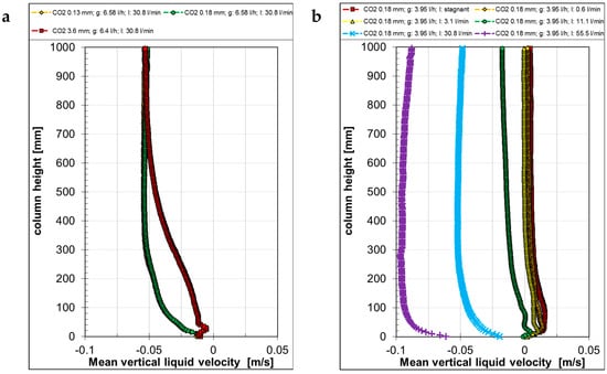
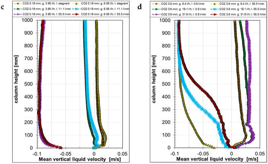
Figure 15.
Mean vertical liquid velocity with CO2 bubbles as a function of the column height, generated with different capillaries (a) at different liquid “l” (b) and gas “g” volume flow rates (c,d).
When increasing the counter-current liquid flow rate, the liquid velocity decreased (Figure 15b) as it did in the case of the air bubbles (Figure 14b). It is also noticeable that the measured liquid velocities remained almost constant above 300 mm, contrary to the results from the air bubbles (Figure 14b) where a constant velocity was only reached higher up in the column. The source of this difference can be found in Figure 7, Figure 8, Figure 9 and Figure 10. The size and velocity of the air bubbles remained nearly the same over the whole investigated height, while the CO2 bubbles shrunk constantly and their velocities decreased during their rise. Due to the decreasing size and velocity, their influence on the liquid flow decreased as well.
The influence of the gas flow rate on the liquid velocity is depicted in Figure 15c,d. As for the air bubbles, just a minor difference was found in the mean vertical velocities for the two lowest gas flow rates from the small capillary under different counter-current liquid flow rates (Figure 15c). Despite the decreasing bubble size and velocity and the increasing bubble aspect ratio, the mean vertical liquid velocity decreased only in the very bottom over the gas inlets and then remained almost constant in the investigated section. Due to the bubble shrinkage and, therefore, weaker upward flow, the vertical liquid velocity reached the single-phase velocity much earlier than in the case of air bubbles. On the other hand, in the case of the 3.6 mm capillaries (Figure 15d), the mean vertical liquid velocity differed appreciably among the different gas flow rates. With increasing gas flow rates, the liquid velocity increased in the lower half of the column before reaching the single-phase flow velocity under the highest counter-current liquid flow rate (yellow, blue, and red symbols). At the lowest counter-current liquid flow rate (orange, green, and purple symbols), the velocity decrease was much smaller and even. At the top, positive, ascending velocities were measured.
4.5. Bubble Slip Velocity
After capturing the bubble and liquid velocities, the relative bubble velocities—also called slip velocities—were calculated by transferring the discrete bubble velocities on a Cartesian coordinate system. Figure 16 shows exemplary slip velocities (calculated from the PIV (liquid velocity) and shadow (bubble velocity) measurements) for the two applied gases at equivalent gas mass flow rates and equal counter-current liquid flow rates. Due to the very small liquid velocities compared to the bubble velocities, the slip velocities were mainly determined by the bubble velocities. The slip velocity of the air bubbles was rather evenly distributed throughout the whole column due to the rather constant bubble velocities in that case. On the other hand, the slip velocity of the CO2 bubbles decreased continuously with the column height, since also the bubble velocities were decreasing for the CO2 bubbles. These slip velocity distribution results were then reduced, in the same manner as that used for the former properties, to mean values over the column width. These are used in the following paragraphs along the column height for further comparisons.
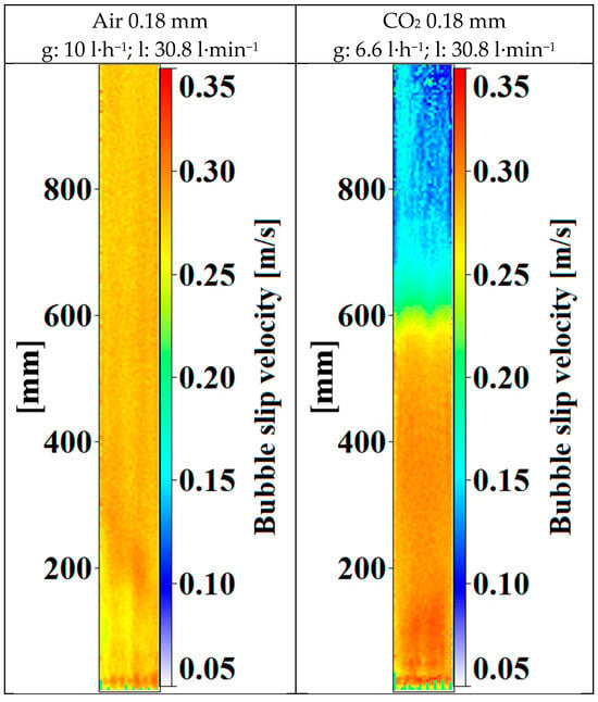
Figure 16.
Mean slip velocities for air and CO2 bubbles, generated with 0.18 mm capillaries at 30.8 l·min−1 liquid and 3.3 mg·s−1 gas mass flow rates.
Figure 17a represents the slip velocities of the air bubbles generated with different capillaries at the same liquid and gas flow rates. Close to the gas inlets, larger velocities can be observed according to the bubble and liquid velocity plots (Figure 9a and Figure 14a).
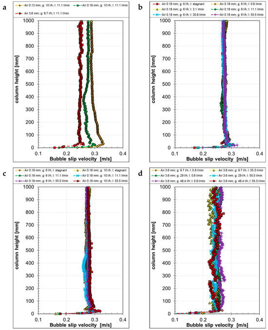
Figure 17.
Mean slip velocity with air bubbles as a function of the column height, generated with different capillaries (a) at different liquid “l” (b) and gas “g” volume flow rates (c,d).
With increasing bubble sizes, the slip velocity decreased and remained almost constant from about half of the column height. With increasing counter-current liquid flow rates (Figure 17b), the bubble velocity, as well as the liquid velocity, decreased; therefore, the calculated slip velocities remained rather constant over the column height. By comparing different gas flow rates for small and large capillaries at different counter-current liquid flow rates (Figure 17c,d), it can be seen that, in both cases—small and large capillaries—the relative velocity remained nearly the same for one capillary size, despite the different bubble sizes (Figure 7) measured over the column height. However, with the 3.6 mm capillaries, larger fluctuations in the slip velocities were observed. All in all, these results are theoretically expected and show the consistency of the separately performed gas and liquid velocity measurements: if the bubble size and shape remain the same, the gas and counter-current liquid flow rates have no influence on the slip velocity.
Describing the slip velocities of the CO2 bubbles (Figure 18) is more complex since mass transfer from the bubbles to the liquid changes the bubble size and shape during their rise. Accordingly, the slip velocity changed as well along the column height. Due to the gradually decreasing bubble size and velocity, the slip velocity decreased continually for all capillary sizes examined (Figure 18a). When the bubbles reached a constant size, shape, and velocity, the slip velocity also became constant.
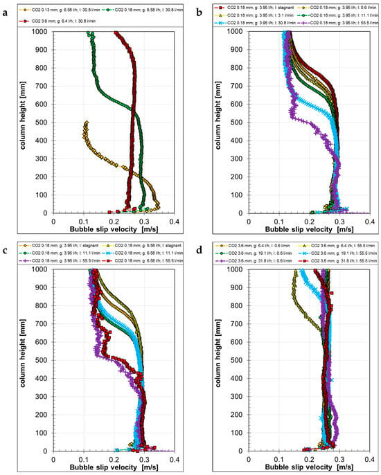
Figure 18.
Mean slip velocity with CO2 bubbles as a function of the column height, generated with different capillaries (a) at different liquid “l” (b) and gas “g” volume flow rates (c,d).
The effect of the counter-current liquid flow is depicted in Figure 18b. The slip velocity for all counter-current liquid flows was constant up to around 300 mm. From this point, the slip velocity decreased, becoming stronger the higher the counter-current liquid flow rate was. With increasing counter-current liquid flow rates, the shrinkage of the bubbles became faster due to the longer contact time with the liquid. With decreasing bubble sizes, the velocity decreased as well and the aspect ratio increased. For this reason, the slip velocity decreased with increasing counter-current liquid flow rates. After the CO2 was depleted from the bubbles, the remaining small gas bubbles became spherical, exhibiting about the same size in the upper part of the column. As it has already been described for the air bubbles, bubbles with the same size and aspect ratio have the same slip velocity, as it can be observed here as well.
The influence of the gas flow rate was weak for the smaller capillary (Figure 18c), but smaller gas flow rates led to a slightly slower slip velocity, especially in the upper half of the column where an influence of the counter-current liquid flow rate became obvious. For the biggest bubbles (Figure 18d), the slip velocity stayed more or less the same, apart from when under the highest counter-current liquid flow rate, where it decreased in the upper part of the column, as it was the case for the bubble velocity.
4.6. Comparison of Mean Bubble Diameters and Aspect Ratios with Literature Correlations
Mean aspect ratios and bubble diameters were finally determined from all measurement results, as mentioned in Section 3 and Figure 6, in order to compare these results to empirical correlations for bubble aspect ratio (Figure 19 and Figure 20). The correlations used here are those of Besagni and Deen [28], obtained from data from different fluid and bubble column combinations, and that of Liu et al. [29] for air bubble swarms in a pseudo-2D column.
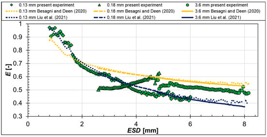
Figure 19.
Relationship between bubble aspect ratio E and equivalent sphere diameter ESD for air bubbles: present measurements and calculations according to [28,29].
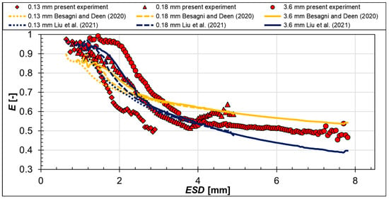
Figure 20.
Relationship between bubble aspect ratio E and equivalent sphere diameter ESD for CO2 bubbles: present measurements and calculations according to [28,29].
It is clearly visible that, with different capillary sizes, that is, different bubble diameters, different bubble aspect ratios were obtained. Moreover, the measurement results for air and CO2 bubbles are similar for the different capillaries (see symbols in Figure 19 and Figure 20). Generally speaking, with increasing bubble diameters, the aspect ratio decreased. Only one exception exists for bubbles produced with the 0.18 mm nozzles and having diameters between 3 mm and 5 mm. Here, the aspect ratio increased with increasing ESD. This behavior may be attributed to the nozzle material, which was Teflon in that case, that behaves differently from the stainless steel and peek nozzles of the other diameters.
These mean aspect ratios are compared to the aforementioned empirical correlations from the literature (see lines in Figure 19 and Figure 20). Globally, both correlations capture well the decreasing trend of the aspect ratio with increasing bubble diameter. However, for both gases used, the correlation of Besagni and Deen [28] underestimated the aspect ratio of bubble diameters up to about 2 mm, while it overestimated the bubble aspect ratios of nearly all cases bigger than 2 mm. The correlation of Liu et al. [29] performed better for the bubble aspect ratios of air bubbles generated with the 0.13 mm capillaries and for the CO2 bubbles generated with the 0.18 mm nozzles. For bubbles bigger than 5 mm, the aspect ratios were mostly underestimated with this correlation.
These discrepancies that cannot be explained by the measurement uncertainty (see Section 2) nor by the validity range of the correlations, show the necessity for more sophisticated correlations, taking into account the gas and liquid properties as well as the bubble generation conditions. Therefore, the actual bubble data presented in this paper are also further used for the evaluation of correlations incorporating these influencing parameters.
5. Conclusions
In this study, shadow imaging experiments of bubbles rising in pure water with and without counter-current liquid flows were acquired, alongside the corresponding liquid velocities, by particle image velocimetry. The results are evaluated to deliver statistical data of bubble diameter, bubble aspect ratio, bubble, liquid, and slip velocities. In the measurements, two types of gases—relatively poorly soluble air and well-soluble CO2—were applied. Moreover, three different capillary diameters were used to generate bubbles of different diameters, ranging from around 1 mm to 9 mm. This comprehensive database of bubble and liquid flow characteristics is presented exemplarily in this paper.
The strong influence of the counter-current liquid flow on the bubble rising behavior and liquid velocity is obvious from these results. It was found that the counter-current liquid flow has a large effect on bubble velocity and motion direction, while also noticeably influencing the generated bubble diameter. Interestingly, the effect of the counter-current liquid flow on the aspect ratio of air bubbles was negligible. However, in the experiments with CO2 bubbles, a significant bubble aspect ratio change was observed due to bubble shrinkage.
The liquid velocity results show that the smaller bubbles generated with the smaller capillaries (0.13 mm and 0.18 mm) had a similar influence on the liquid flow velocity under all investigated conditions for both gases. Moreover, in the case of air bubbles under higher counter-current liquid flow rates, the liquid velocity reached nearly the single-phase flow velocity in the upper part of the column. For CO2 bubbles, the single-phase velocity was reached much earlier due to bubble shrinkage.
The large bubbles generated with the largest capillaries (3.6 mm) had a stronger influence on the liquid flow all over the investigated height and the liquid velocity did not decrease to the single-phase velocity, apart from when under the highest counter-current liquid flow rate with CO2 bubbles.
It was found that due to the small liquid velocities compared to the bubble velocities, the slip velocities were mainly determined by the bubble velocities. The results show that the slip velocities were independent from the counter-current liquid flow rate as well as from the gas flow rate for the same capillaries. For this reason, the slip velocity remained constant over the column height for each capillary size in the cases involving air bubbles. In the cases involving CO2 bubbles, the slip velocity decreased to a speed similar to that of the bubble velocity. When these bubbles reached a constant size, shape, and velocity, the slip velocity also became constant.
This comprehensive database was further used for the determination of correlations, e.g., for bubble aspect ratio, and for the validation of numerical methods [17]. It is available upon request from the authors for the interested readers.
Author Contributions
Conceptualization, P.K. and K.Z.; Methodology, P.K. and K.Z.; Investigation, P.K.; Data curation, P.K.; Writing—original draft, P.K.; Writing—review & editing, P.K. and K.Z.; Visualization, P.K. and K.Z.; Supervision, K.Z.; Project administration, K.Z.; Funding acquisition, K.Z. All authors have read and agreed to the published version of the manuscript.
Funding
This research was funded by the German Research foundation (DFG) under grant No. ZA 527/3-1.
Data Availability Statement
Data is available upon request from the authors.
Acknowledgments
Authors would also like to thank their students Steffen Erichson and Maximilian Mahler for their help in doing the original experiments and Anselm Dreher for programming the evaluation routines.
Conflicts of Interest
The authors declare no conflict of interest.
Nomenclature
| d | Diameter of bubble column | m |
| E | Bubble aspect ratio | - |
| h | Height of bubble column | m |
| hb | Short bubble axis | m |
| lb | Long bubble axis | m |
| vLs | Superficial liquid velocity | m/s |
| μL | Liquid dynamic viscosity | Pa.s |
| ρL | Liquid density | kg/m3 |
| ESD | Equivalent sphere diameter | |
| PIV | Particle image velocimetry | |
| PTV | Particle tracking velocimetry |
References
- Joshi, J.B.; Nandakumar, K.; Evans, G.M.; Pareek, V.K.; Gumulya, M.M.; Sathe, M.J.; Khanwale, M.A. Bubble generated turbulence and direct numerical simulations. Chem. Eng. Sci. 2017, 157, 26–75. [Google Scholar] [CrossRef]
- Bando, Y.; Nishimura, M.; Sota, H.; Suzuki, S.; Kawase, N. Flow characteristics of countercurrent bubble column with perforated draft tube. Chem. Eng. Sci. 1992, 47, 3371–3378. [Google Scholar] [CrossRef]
- Besagni, G.; Di Pasquali, A.; Gallazzini, L.; Gottardi, E.; Colombo, L.P.M.; Inzoli, F. The effect of aspect ratio in counter-current gas-liquid bubble columns: Experimental results and gas holdup correlations. Int. J. Multiph. Flow 2017, 94, 53–78. [Google Scholar] [CrossRef]
- Besagni, G.; Guédon, G.; Inzoli, F. Experimental investigation of counter current air-water flow in a large diameter vertical pipe with inners. J. Phys. Conf. Ser. 2014, 547, 012024. [Google Scholar] [CrossRef]
- Besagni, G.; Inzoli, F. Comprehensive experimental investigation of counter-current bubble column hydrodynamics: Holdup, flow regime transition, bubble size distributions and local flow properties. Chem. Eng. Sci. 2016, 146, 259–290. [Google Scholar] [CrossRef]
- Biń, A.K.; Duczmal, B.; Machniewski, P. Hydrodynamics and ozone mass transfer in a tall bubble column. Chem. Eng. Sci. 2001, 56, 6233–6240. [Google Scholar] [CrossRef]
- Eissa, S.H.; Schügerl, K. Holdup and backmixing investigations in cocurrent and countercurrent bubble columns. Chem. Eng. Sci. 1975, 30, 1251–1256. [Google Scholar] [CrossRef]
- Jin, H.; Yang, S.; He, G.; Wang, M.; Williams, R.A. The effect of gas-liquid counter-current operation on gas hold-up in bubble columns using electrical resistance tomography. J. Chem. Technol. Biotechnol. 2010, 85, 1278–1283. [Google Scholar] [CrossRef]
- Kalaga, D.V.; Ansari, M.; Turney, D.E.; Hernandez-Alvarado, F.; Kleinbart, S.; ArunKumar, K.E.; Joshi, J.B.; Banerjee, S.; Kawaji, M. Scale-up of a downflow bubble column: Experimental investigations. Chem. Eng. J. 2020, 386, 121447. [Google Scholar] [CrossRef]
- Otake, T.; Tone, S.; Shinohara, K. Gas holdup in the bubble column with cocurrent and countercurrent gas-liquid flow. J. Chem. Eng. Jpn. 1981, 14, 338–340. [Google Scholar] [CrossRef]
- Seno, T.; Uchida, S.; Tsuyutani, S. Mass transfer in countercurrent and cocurrent bubble columns. Chem. Eng. Technol. 1990, 13, 113–118. [Google Scholar] [CrossRef]
- Uchida, S.; Tsuyutani, S.; Seno, T. Flow regimes and mass transfer in counter-current bubble columns. Can. J. Chem. Eng. 1989, 67, 866–869. [Google Scholar] [CrossRef]
- Akita, K.; Yoshida, F. Gas Holdup and Volumetric Mass Transfer Coefficient in Bubble Columns. Effects of Liquid Properties. Ind. Eng. Chem. Process Des. Dev. 2002, 12, 76–80. [Google Scholar] [CrossRef]
- Besagni, G.; Brazzale, P.; Fiocca, A.; Inzoli, F. Estimation of bubble size distributions and shapes in two-phase bubble column using image analysis and optical probes. Flow Meas. Instrum. 2016, 52, 190–207. [Google Scholar] [CrossRef]
- Besagni, G.; Inzoli, F. Bubble size distributions and shapes in annular gap bubble column. Exp. Therm. Fluid Sci. 2016, 74, 27–48. [Google Scholar] [CrossRef]
- Kováts, P.; Zähringer, K. Statistical analysis of bubble parameters from a model bubble column with and without counter-current flow. In Proceedings of the 20th International Symposium on the Application of Laser and Imaging Techniques to Fluid Mechanics, Lisbon, Portugal, 11–14 July 2022; p. 1011. [Google Scholar]
- Khan, H.; Kováts, P.; Zähringer, K.; Rzehak, R. Experimental and numerical investigation of a counter-current flow bubble column. Chem. Eng. Sci. 2024, 285, 119503. [Google Scholar] [CrossRef]
- Mühlbauer, A.; Hlawitschka, M.W.; Bart, H.-J. Models for the Numerical Simulation of Bubble Columns: A Review. Chem. Ing. Tech. 2019, 91, 1747–1765. [Google Scholar] [CrossRef]
- Rzehak, R.; Krauß, M.; Kováts, P.; Zähringer, K. Fluid dynamics in a bubble column: New experiments and simulations. Int. J. Multiph. Flow 2017, 89, 299–312. [Google Scholar] [CrossRef]
- Sommerfeld, M.; Muniz, M.; Reichardt, T. On the Importance of Modelling Bubble Dynamics for Point-mass Numerical Calculations of Bubble Columns. J. Chem. Eng. Jpn. 2018, 51, 301–317. [Google Scholar] [CrossRef]
- Kováts, P.; Thévenin, D.; Zähringer, K. Influence of viscosity and surface tension on bubble dynamics and mass transfer in a model bubble column. Int. J. Multiph. Flow 2020, 123, 103174. [Google Scholar] [CrossRef]
- Kováts, P. Detailed Experimental Study of Mass Transfer and Liquid Flow in a Bubble Column with Optical Measurement Techniques. Ph.D. Thesis, Otto-von-Guericke-Universität Magdeburg, Magdeburg, Germany, 2021. [Google Scholar] [CrossRef]
- Wieneke, B. PIV uncertainty quantification from correlation statistics. Meas. Sci. Technol. 2015, 26, 074002. [Google Scholar] [CrossRef]
- Hosoda, S.; Abe, S.; Hosokawa, S.; Tomiyama, A. Mass transfer from a bubble in a vertical pipe. Int. J. Heat Mass Transf. 2014, 69, 215–222. [Google Scholar] [CrossRef]
- Merker, D.; Böhm, L.; Ossberger, M.; Klüfers, P.; Kraume, M. Mass Transfer in Reactive Bubbly Flows—A Single-Bubble Study. Chem. Eng. Technol. 2017, 40, 1391–1399. [Google Scholar] [CrossRef]
- Ishii, M.; Zuber, N. Drag coefficient and relative velocity in bubbly, droplet or particulate flows. AIChE J. 1979, 25, 843–855. [Google Scholar] [CrossRef]
- Tomiyama, A.; Kataoka, I.; Zun, I.; Sakaguchi, T. Drag Coefficients of Single Bubbles under Normal and Micro Gravity Conditions. JSME Int. J. Ser. B 1998, 41, 472–479. [Google Scholar] [CrossRef]
- Besagni, G.; Deen, N.G. Aspect ratio of bubbles in different liquid media: A novel correlation. Chem. Eng. Sci. 2020, 215, 115383. [Google Scholar] [CrossRef]
- Liu, L.; Zhang, H.; Yan, H.; Ziegenhein, T.; Hessenkemper, H.; Zhou, P.; Lucas, D. Experimental studies on bubble aspect ratio and corresponding correlations under bubble swarm condition. Chem. Eng. Sci. 2021, 236, 116551. [Google Scholar] [CrossRef]
Disclaimer/Publisher’s Note: The statements, opinions and data contained in all publications are solely those of the individual author(s) and contributor(s) and not of MDPI and/or the editor(s). MDPI and/or the editor(s) disclaim responsibility for any injury to people or property resulting from any ideas, methods, instructions or products referred to in the content. |
© 2024 by the authors. Licensee MDPI, Basel, Switzerland. This article is an open access article distributed under the terms and conditions of the Creative Commons Attribution (CC BY) license (https://creativecommons.org/licenses/by/4.0/).