
Comparison between Areas of Bone Visualization Using Radiolucent Hybrid Fixator Frames and Graphically Simulated Metallic Frames: An Ex Vivo Study

 , ,
, ,
Abstract
1. Introduction
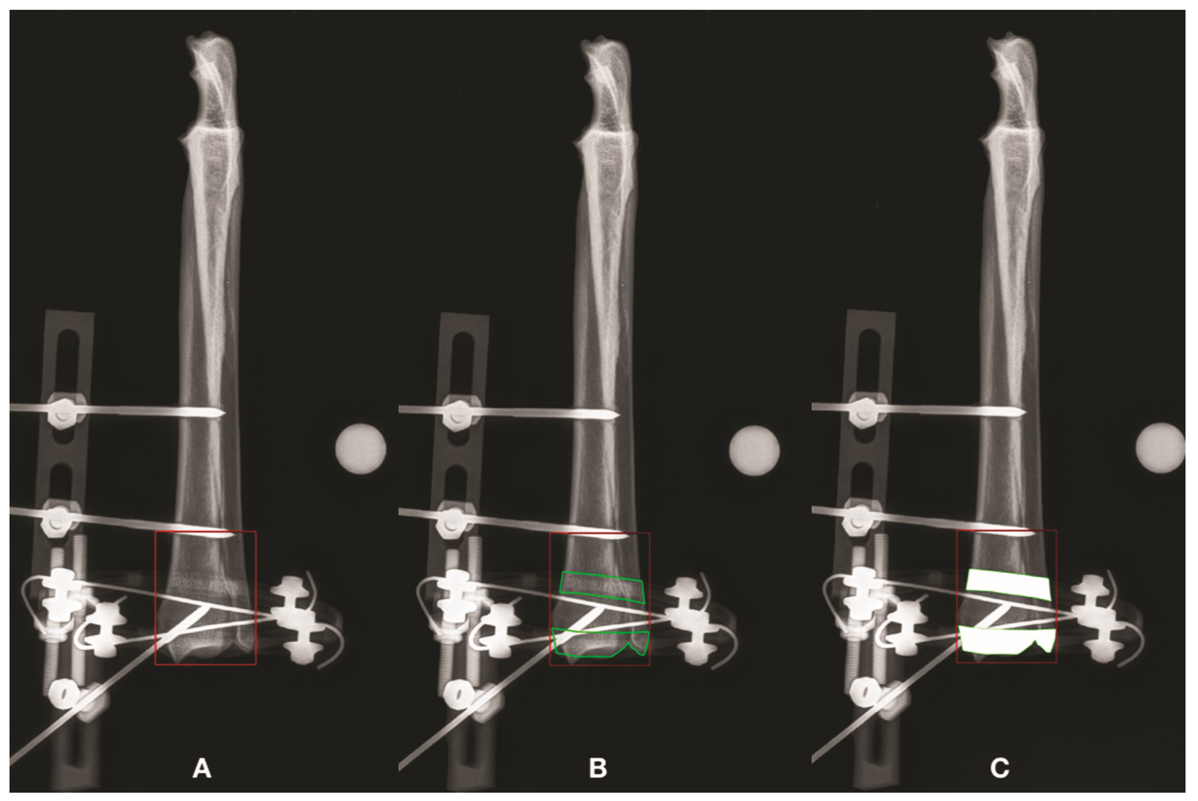
2. Materials and Methods
3. Results
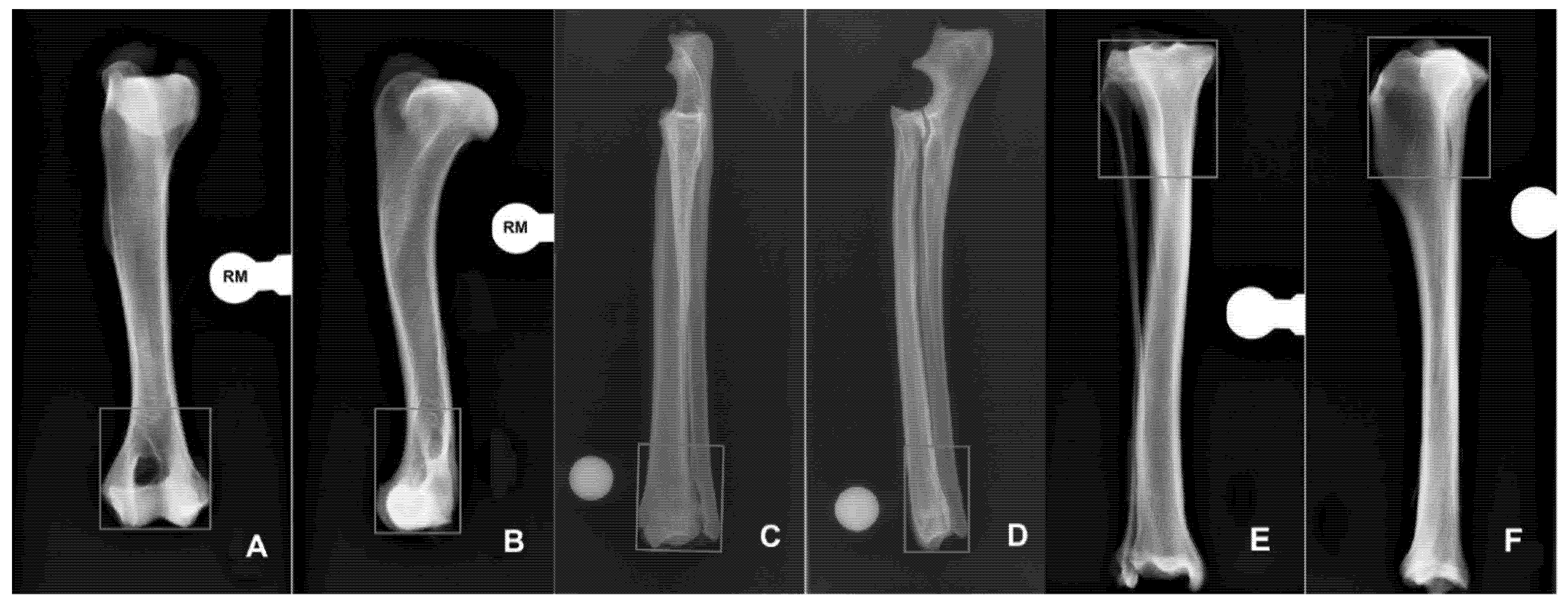
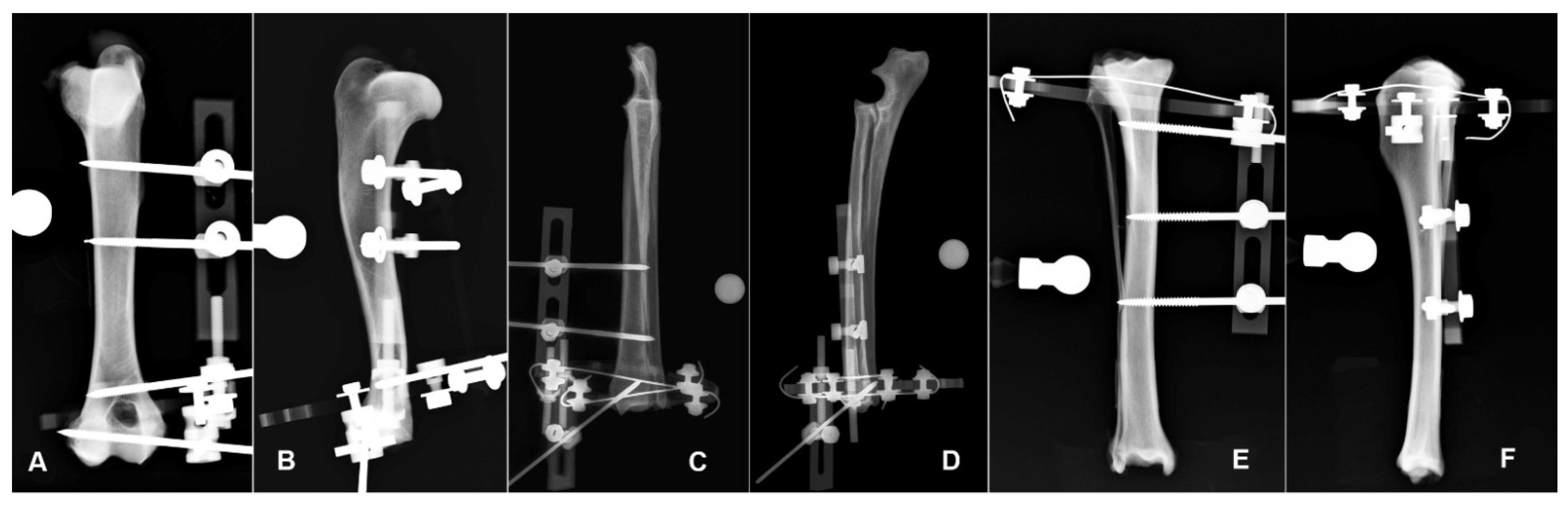
3.1. Humerus
3.2. Radius-Ulna
3.3. Tibia
4. Discussion
5. Conclusions
Author Contributions
Funding
Institutional Review Board Statement
Informed Consent Statement
Data Availability Statement
Conflicts of Interest
References
- Anderson, G.M.; Lewis, D.D.; Radasch, R.M.; Marcellin-Little, D.J.; Degna, M.T.; Cross, A.R. Circular external skeletal fixation stabilization of antebrachial and crural fractures in 25 dogs. J. Am. Anim. Hosp. Assoc. 2003, 39, 479–498. [Google Scholar] [CrossRef] [PubMed]
- Radasch, R.M.; Lewis, D.F.; Mcdonald, D.E. Pes varus correction in Dachshunds using a hybrid external fixator. Vet. Surg. 2008, 37, 71–81. [Google Scholar] [CrossRef] [PubMed]
- Rovesti, G.L.; Bosio, A.; Marcellin Little, D.J. Management of 49 antebrachial and crural fractures in dogs using circular external fixators. J. Small Anim. Pract. 2007, 48, 194–200. [Google Scholar] [CrossRef] [PubMed]
- Cross, A.R.; Lewis, D.D.; Murphy, S.T.; Rigaud, S.; Madison, J.B.; Kehoe, M.M.; Rapoff, A.J. Effects of ring diameter and wire tension on the axial biomechanics of four-ring circular external skeletal fixator constructs. Am. J. Vet. Res. 2001, 62, 1025–1030. [Google Scholar] [CrossRef] [PubMed]
- Socie, M.J.; Rovesti, G.L.; Griffon, D.J.; Elkhatib, O.; Mudrock, R.N.; Kurath, P. Biomechanical comparison of strategies to adjust axial stiffness of a hybrid fixator. Vet. Comp. Orthop. Traumatol. 2012, 25, 224–230. [Google Scholar] [CrossRef] [PubMed]
- Clarke, S.P.; Carmichael, S. Treatment of distal diaphyseal fractures using hybrid external skeletal fixation in three dogs. J. Small Anim. Pract. 2006, 47, 98–103. [Google Scholar] [CrossRef]
- Yardimci, C.; Ozak, A.; Nisbet, H.O. 2011. Management of femoral fractures in dogs with unilateral semicircular external skeletal fixators. Vet. Surg. 2011, 40, 379–387. [Google Scholar] [CrossRef]
- Hadeed, A.; Werntz, R.L.; Varacallo, M. External Fixation Principles and Overview. In StatPearls [Internet]; StatPearls Publishing: Treasure Island, FL, USA, 2022. [Google Scholar]
- Dudley, M.; Johnson, A.L.; Olmstead, M.; Smith, C.W.; Schaeffer, D.J.; Abbuehl, U. Open reduction and bone plate stabilization, compared with closed reduction and external fixation, for treatment of comminuted tibial fractures: 47 cases (1980–1995) in dogs. J. Am. Med. Vet. Assoc. 1997, 15, 1008–1012. [Google Scholar]
- Gauthier, C.M.; Kowaleski, M.P.; Gerard, P.D.; Rovesti, G.L. Comparison of the axial stiffness of carbon composite and aluminium alloy circular external skeletal fixator rings. Vet. Comp. Orthop. Traumatol. 2013, 26, 172–176. [Google Scholar]
- Dall’oca, C.; Christodoulidis, A.; Bortolazzi, R.; Bartolozzi, P.; Lavini, F. Treatment of 103 displaced tibial diaphyseal fractures with a radiolucent unilateral external fixator. Arch. Orthop. Trauma Surg. 2010, 130, 1377–1382. [Google Scholar] [CrossRef] [PubMed]
- Caiaffa, V.; Cagnazzo, R.; Fraccascia, A.; Freda, V. Radiolucent external fixator: Three years experience. Orthop. Proc. 2006, 88-B, 419. [Google Scholar]
- Lavini, F.; Dall’Oca, C.; Bortolazzi, R.; Bartolozzi, P. Radiolucent external fixator. J. Bone Joint Surg. Br. 2005, 87-B, 179. [Google Scholar]
- Baidya, K.P.; Ramakrishna, S.; Rahman, M.; Ritchie, A.; Huang, Z.-M. An Investigation on the Polymer Composite Medical Device—External Fixator. J. Reinf. Plast. Compos. 2003, 22, 563–590. [Google Scholar] [CrossRef]
- Iobst, C.A. New Trends in Ring Fixators. J. Pediatr. Orthop. 2017, 37, S18–S21. [Google Scholar] [CrossRef] [PubMed]
- Jiménez-Heras, M.; Rovesti, G.; Nocco, G.; Barilli, M.; Bogoni, P.; Salas-Herreros, E.; Armato, M.; Collivignarelli, F.; Vegni, F.; Rodríguez-Quiros, J. Evaluation of sixty-eight cases of fracture stabilization by external hybrid fixation and a proposal for hybrid construct classification. BMC Vet. Res. 2014, 10, 189. [Google Scholar] [CrossRef] [PubMed]
- Kirkby, K.A.; Lewis, D.D.; Lafuente, M.P.; Radasch, R.M.; Fitzpatrick, N.; Farese, J.P.; Wheeler, J.L.; Hernandez, J.A. Management of humeral and femoral fractures in dogs and cats with linear- circular hybrid external skeletal fixators. J. Am. Anim. Hosp. Assoc. 2008, 44, 180–197. [Google Scholar] [CrossRef]
- Baidya, K.P.; Ramakrishna, S.; Rahman, M.; Ritchie, A. Quantitative radiographic analysis of fiber reinforced polymer composites. J. Biomater. Appl. 2001, 15, 279–289. [Google Scholar] [CrossRef]
- Kowalski, M.; Schemitsch, E.H.; Harrington, R.M.; Chapman, J.R.; Swiontkowski, M.F. Comparative biomechanical evaluation of different external fixation sidebars: Stainless-steel tubes versus carbon fiber rods. Orthop. Trauma. 1996, 10, 470–475. [Google Scholar] [CrossRef]
- Nele, U.; Maffulli, N.; Pintore, E. Biomechanics of radiotransparent circular external fixators. Clin. Orthop. Relat. Res. 1994, 308, 68–72. [Google Scholar] [CrossRef]
- Caja, V.L.; Kim, W.; Larsson, S.; Chao, E.Y. Comparison of the mechanical performance of three types of external fixators: Linear, circular and hybrid. Clin. Biomech. 1995, 10, 401–406. [Google Scholar] [CrossRef]
- Hudson, C.C.; Lewis, D.D.; Cross, A.R.; Dunbar, N.J.; Horodyski, M.; Banks, S.A.; Pozzi, A. A biomechanical comparison of three hybrid linear-circular external fixator constructs. Vet. Surg. 2012, 41, 954–965. [Google Scholar] [CrossRef]
- Pearson, T.; Glyde, M.; Hosgood, G.; Day, R. The effect of intramedullary pin size and monocortical screw configuration on locking compression plate-rod constructs in an in vitro fracture gap model. Vet. Comp. Orthop. Traumatol. 2015, 28, 95–103. [Google Scholar] [PubMed]
- Hutcheson, K.D.; Butler, J.R.; Elder, S.E. Comparison of double locking plate constructs with single non-locking plate constructs in single cycle to failure in bending and torsion. Vet. Comp. Orthop. Traumatol. 2015, 28, 234–239. [Google Scholar] [CrossRef] [PubMed]
- Field, E.J.; Parsons, K.; Etches, J.A.; Hamilton, K.; Burton, N.J. Effect of monocortical and bicortical screw numbers on the properties of a locking plate-intramedullary rod configuration. An in vitro study on a canine femoral fracture gap model. Vet. Comp. Orthop. Traumatol. 2016, 29, 459–465. [Google Scholar] [PubMed]
- Demner, D.; Garcia, T.C.; Serdy, M.G.; Hayashi, K.; Nir, B.A.; Stover, S.M. Biomechanical comparison of mono- and bicortical screws in an experimentally induced gap fracture. Vet. Comp. Orthop. Traumatol. 2014, 27, 422–429. [Google Scholar]
- Rowe-Guthrie, K.M.; Markel, M.D.; Bleedorn, J.A. Mechanical Evaluation of Locking, Nonlocking, and Hybrid Plating Constructs Using a Locking Compression Plate in a Canine Synthetic Bone Model. Vet Surg. 2015, 44, 838–842. [Google Scholar] [CrossRef] [PubMed]
- Ahmad, M.; Nanda, R.; Bajwa, A.S.; Candal-Couto, J.; Green, S.; Hui, A.C. Biomechanical testing of the locking compression plate: When does the distance between bone and implant significantly reduce construct stability? Injury 2007, 38, 358–364. [Google Scholar] [CrossRef] [PubMed]
- Aguila, A.Z.; Manos, J.M.; Orlansky, A.S.; Todhunter, R.J.; Trotter, E.J.; Van der Meulen, M.C. In vitro biomechanical comparison of limited contat dynamic compression plate and locking compression plate. Vet. Comp. Orthop. Traumatol. 2005, 18, 220–226. [Google Scholar] [PubMed]
- Augat, P.; Margevicius, K.; Simon, J.; Wolf, S.; Suger, G.; Claes, L. Local tissue properties in bone healing: Influence of size and stability of the osteotomy gap. J. Orthop. Res. 1998, 16, 475–481. [Google Scholar] [CrossRef] [PubMed]


| Bone Segment | Case | Projection | FA (mm2) | RLA (mm2) | ROA (mm2) | RLA-ROA (mm2) | FA/RLA (%) | FA/ROA | FA/ROA (%) | RLA/ROA | RLA/ROA (%) | Statistical Result |
|---|---|---|---|---|---|---|---|---|---|---|---|---|
| Humerus | ||||||||||||
| 1 | AP | 1958.33 | 1958.33 | 1838.28 | 120.06 | 1.00 (100) | 1.07 | 107 | 1.07 | 107 | ||
| 1 | ML | 1888.4 | 1870.82 | 1713.13 | 157.69 | 1.01 (101) | 1.1 | 110 | 1.09 | 109 | ||
| 2 | AP | 1966.67 | 1966.67 | 1581.47 | 385.2 | 1.00 (100) | 1.24 | 124 | 1.24 | 124 | ||
| 2 | ML | 1404.31 | 931.4 | 752.07 | 179.33 | 1.51 (151) | 1.87 | 187 | 1.24 | 124 | ||
| 3 | AP | 1969.76 | 1969.76 | 1543.45 | 426.3 | 1.00 (100) | 1.28 | 128 | 1.28 | 128 | ||
| 3 | ML | 1227.68 | 715.65 | 583.74 | 131.92 | 1.72 (172) | 2.1 | 210 | 1.23 | 123 | ||
| 4 | AP | 1824.27 | 1824.27 | 1627.47 | 196.8 | 1.00 (100) | 1.12 | 112 | 1.12 | 112 | ||
| 4 | ML | 1421.43 | 854.83 | 745.95 | 108.88 | 1.66 (166) | 1.91 | 191 | 1.15 | 115 | ||
| 5 | AP | 1879.15 | 1879.15 | 1618.41 | 260.74 | 1.00 (100) | 1.16 | 116 | 1.16 | 116 | ||
| 5 | ML | 1353.75 | 1138.71 | 1053.82 | 84.89 | 1.19 (119) | 1.28 | 128 | 1.08 | 108 | ||
| 6 | AP | 1779.92 | 1779.92 | 1553.29 | 226.63 | 1.00 (100) | 1.15 | 115 | 1.15 | 115 | ||
| 6 | ML | 1315.31 | 839.31 | 724.42 | 114.89 | 1.57 (157) | 1.82 | 182 | 1.16 | 116 | ||
| Median | AP | 1918.74 | 1918.74 | 1599.94 | 243.68 | 1 | 1.15 | 115.35 | 1.15 | 115.35 | p = 0.0143 | |
| ML | 1379.03 | 893.12 | 749.01 | 123.4 | 1.54 | 1.84 | 184.15 | 1.15 | 115.23 | p = 0.0143 | ||
| (range) | AP | (1779.92–1969.76) | (1779.92–1969.76) | (1543.45–1838.28) | (120.06–426.30) | (1.00–1,00) | (1.07–1.28) | (106.53–127.62) | (1.07–1.28) | (106.53–127.62) | ||
| ML | (1227.68–1888.40) | (715.65–1870.82) | (583.74–17,134.13) | (84.89–179.33) | (1.01–1.72) | (1.10–2.10) | (110.23–210.31) | (1.08–1.24) | (108.06–123.84) |
| Bone Segment | Case | Projection | FA (mm2) | RLA (mm2) | ROA (mm2) | RLA-ROA (mm2) | FA/RLA (%) | FA/ROA | FA/ROA (%) | RLA/ROA | RLA/ROA (%) | Statistical Result |
|---|---|---|---|---|---|---|---|---|---|---|---|---|
| Radius-Ulna | ||||||||||||
| 1 | AP | 2009.08 | 2009.08 | 1435.62 | 573.46 | 1.00 (100) | 1.4 | 140 | 1.4 | 140 | ||
| 1 | ML | 1221.11 | 949.46 | 731.71 | 217.75 | 1.29 (129) | 1.67 | 167 | 1.3 | 130 | ||
| 2 | AP | 2073.31 | 1962.72 | 1384.6 | 578.12 | 1.06 (106) | 1.5 | 150 | 1.42 | 142 | ||
| 2 | ML | 1333.83 | 1317.29 | 1110.59 | 206.69 | 1.01 (101) | 1.2 | 120 | 1.19 | 119 | ||
| 3 | AP | 1587.06 | 1587.06 | 1130.68 | 456.39 | 1.00 (100) | 1.4 | 140 | 1.4 | 140 | ||
| 3 | ML | 1020.26 | 745.04 | 440.14 | 304.9 | 1.37 (137) | 2.32 | 232 | 1.69 | 169 | ||
| 4 | AP | 1823.71 | 1823.71 | 1204.22 | 619.49 | 1.00 (100) | 1.51 | 151 | 1.51 | 151 | ||
| 4 | ML | 1187.93 | 801.14 | 484.13 | 317.01 | 1.48 (148) | 2.45 | 245 | 1.65 | 165 | ||
| 5 | AP | 1661.69 | 1661.69 | 1232.98 | 428.71 | 1.00 (100) | 1.35 | 135 | 1.35 | 135 | ||
| 5 | ML | 942.22 | 673.3 | 412.01 | 261.29 | 1.40 (140) | 2.29 | 229 | 1.63 | 163 | ||
| 6 | AP | 2009.08 | 2009.08 | 1435.62 | 573.46 | 1.00 (100) | 1.4 | 140 | 1.4 | 140 | ||
| 6 | ML | 1431.98 | 1295.45 | 761.4 | 534.05 | 1.11 (111) | 1.88 | 188 | 1.7 | 170 | ||
| Median | AP | 1785.13 | 1785.13 | 1256.49 | 520.01 | 1 | 1.4 | 140.15 | 1.4 | 140.15 | p = 0.0143 | |
| ML | 1204.52 | 857.3 | 607.92 | 283.1 | 1.33 | 2.08 | 208.38 | 1.64 | 164.45 | p = 0.0143 | ||
| (range) | AP | (1587.06–2073.31) | (1587.06–2009.08) | (1130.68–1435.62) | (428.71–619.49) | (1.00–1.06) | (1.35–1.51) | (134.77–151.44) | (1.35–1.51) | (134.77–151.44) | ||
| ML | (942.22–1431.98) | (673.30–1317.29) | (412.01–1110.59) | (206.69–534.05) | (1.01–1.48) | (1.20–2.45) | (120.10–245.38) | (1.19–1.70) | (118.61–170.14) |
| Bone Segment | Case | Projection | FA (mm2) | RLA (mm2) | ROA (mm2) | RLA-ROA (mm2) | FA/RLA (%) | FA/ROA | FA/ROA (%) | RLA/ROA | RLA/ROA (%) | Statistical Result |
|---|---|---|---|---|---|---|---|---|---|---|---|---|
| Tibia | ||||||||||||
| 1 | AP | 2448.26 | 2448.26 | 2193.1 | 255.16 | 1.00 (100) | 1.12 | 112 | 1.12 | 112 | ||
| 1 | ML | 2368.11 | 1858.46 | 1594.34 | 264.12 | 1.27 (127) | 1.49 | 149 | 1.17 | 117 | ||
| 2 | AP | 2181.06 | 2181.06 | 1906.42 | 274.64 | 1.00 (100) | 1.14 | 114 | 1.14 | 114 | ||
| 2 | ML | 2522.34 | 2118.95 | 1532.54 | 586.41 | 1.19 (119) | 1.65 | 165 | 1.38 | 138 | ||
| 3 | AP | 2034.36 | 2034.36 | 1771.65 | 262.71 | 1.00 (100) | 1.15 | 115 | 1.15 | 115 | ||
| 3 | ML | 1885.76 | 1448 | 1090.29 | 357.72 | 1.30 (130) | 1.73 | 173 | 1.33 | 133 | ||
| 4 | AP | 1994.06 | 1994.06 | 1718.91 | 275.15 | 1.00 (100) | 1.16 | 116 | 1.16 | 116 | ||
| 4 | ML | 1917.27 | 1636.64 | 1241.88 | 394.76 | 1.17 (117) | 1.54 | 154 | 1.32 | 132 | ||
| 5 | AP | 2298.43 | 2298.43 | 1982.56 | 315.87 | 1.00 (100) | 1.16 | 116 | 1.16 | 116 | ||
| 5 | ML | 2171.56 | 1898.04 | 1512.37 | 385.67 | 1.14 (114) | 1.44 | 144 | 1.26 | 126 | ||
| 6 | AP | 2913.71 | 2913.71 | 2614.23 | 299.48 | 1.00 (100) | 1.11 | 111 | 1.11 | 111 | ||
| 6 | ML | 2553.02 | 2283.24 | 1722.48 | 560.76 | 1.12 (112) | 1.48 | 148 | 1.33 | 133 | ||
| Median | AP | 2239.75 | 2239.75 | 1944.49 | 274.89 | 1 | 1.15 | 114.62 | 1.15 | 114.62 | p = 0.0143 | |
| ML | 2269.84 | 1878.25 | 1522.45 | 390.21 | 1.18 | 1.51 | 151.46 | 1.32 | 132.17 | p = 0.0143 | ||
| (range) | AP | (1994.06–2913.71) | (1994.06–2913.71) | (1718.91–2614.23) | (255.16–315.87) | (1.00–1.00) | (1.11–1.16) | (111.46–116.01) | (1.11–1.16) | (111.46–116.01) | ||
| ML | (1885.76–2553.02) | (1448.00–2283.24) | (1090.29–1722.48) | (264.12–586.41) | (1.12–1.30) | (1.44–1.73) | (143.59–172.96) | (1.17–1.38) | (116.57–138.26) |
Publisher’s Note: MDPI stays neutral with regard to jurisdictional claims in published maps and institutional affiliations. |
© 2022 by the authors. Licensee MDPI, Basel, Switzerland. This article is an open access article distributed under the terms and conditions of the Creative Commons Attribution (CC BY) license (https://creativecommons.org/licenses/by/4.0/).
Share and Cite
Bonardi, A.; Rovesti, G.L.; Martini, F.M.; Dondi, F.; Benedini, D.; Barbieri, F. Comparison between Areas of Bone Visualization Using Radiolucent Hybrid Fixator Frames and Graphically Simulated Metallic Frames: An Ex Vivo Study. Vet. Sci. 2022, 9, 120. https://doi.org/10.3390/vetsci9030120
Bonardi A, Rovesti GL, Martini FM, Dondi F, Benedini D, Barbieri F. Comparison between Areas of Bone Visualization Using Radiolucent Hybrid Fixator Frames and Graphically Simulated Metallic Frames: An Ex Vivo Study. Veterinary Sciences. 2022; 9(3):120. https://doi.org/10.3390/vetsci9030120
Chicago/Turabian StyleBonardi, Andrea, Gian Luca Rovesti, Filippo Maria Martini, Francesco Dondi, Davide Benedini, and Fabio Barbieri. 2022. "Comparison between Areas of Bone Visualization Using Radiolucent Hybrid Fixator Frames and Graphically Simulated Metallic Frames: An Ex Vivo Study" Veterinary Sciences 9, no. 3: 120. https://doi.org/10.3390/vetsci9030120
APA StyleBonardi, A., Rovesti, G. L., Martini, F. M., Dondi, F., Benedini, D., & Barbieri, F. (2022). Comparison between Areas of Bone Visualization Using Radiolucent Hybrid Fixator Frames and Graphically Simulated Metallic Frames: An Ex Vivo Study. Veterinary Sciences, 9(3), 120. https://doi.org/10.3390/vetsci9030120