Abstract
This study presents the synthesis, electrochemical characterization, and sensor application of Na3[Fe(CN)5(PZT)], a novel pentacyanidoferrate-based coordination compound incorporating 2-pyrazinylethanethiol (PZT) as a ligand. Unlike conventional Prussian blue analogues, this system exhibits enhanced electrocatalytic properties due to its unique ligand framework, which contributes to increased charge transfer efficiency and stability. The complex was synthesized via a controlled ligand substitution reaction, followed by UV-Vis and IR spectroscopy confirmation of its successful formation. The electrochemical properties of the Na3[Fe(CN)5(PZT)] complex were investigated using cyclic voltammetry (CV), differential pulse voltammetry (DPV), square-wave voltammetry (SWV), and electrochemical impedance spectroscopy (EIS). Notably, the modified electrodes exhibited improved charge transfer kinetics and catalytic activity, making them promising candidates for electrochemical sensing applications. The Na3[Fe(CN)5(PZT)]-modified electrode demonstrated outstanding electrocatalytic performance towards hydrazine oxidation, exhibiting a low detection limit of 7.38 × 10⁻⁶ M, a wide linear response range from 5 to 64 µmol L−1, and high sensitivity. The proposed system enables precise quantification of hydrazine with high selectivity, positioning Na3[Fe(CN)5(PZT)] as an effective electrochemical mediator for advanced sensing platforms. These findings provide new insights into the design of next-generation Prussian blue analogue-based sensors with superior analytical performance.
1. Introduction
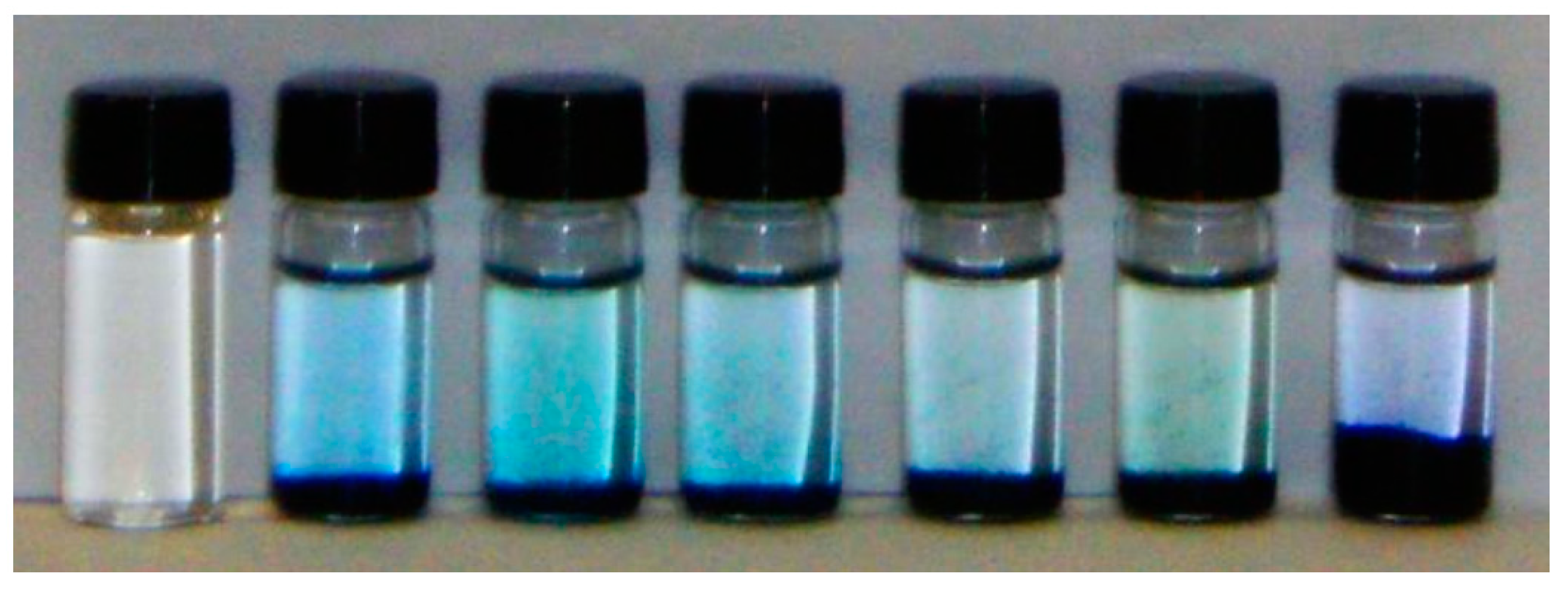
Hexacyanoferrate (HCF) and several pentacyanideferrates (PCFs) were described in the literature in the 19th and 20th centuries [1,2]. Typically, PCFs are synthesized from HCF, nitroprusside, or aminopentacian aldehyde [3,4]. A very striking point in PCF studies is the charge transfer band in the visible region, which gives these complexes an intense color; this can be seen in Figure 1.
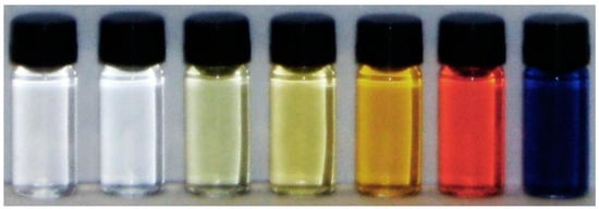
Figure 1.
Aqueous solutions of PCF [Fe(CN)5X]. X from left to right: nitro (NO), cyanide (CN−), aqua (H2O), amino (NH3), isonicotinate (C6H4NO2), pyrazine (C4H4N2), and methylpyrazinium (C5H7N2).
Another important feature of these cyanide complexes is their ability to form bridging bonds, resulting in materials with structures like Prussian blue (PB) [5,6,7]. This unique material has well-defined electrochemical properties and this type of material can be called an electroactive coordination polymer (ECP). Prussian blue (Figure 2) is an inorganic polymer with the characteristics of a metal–organic framework (MOF). It was discovered accidentally by Diesbach and Dippel in the early 18th century, and is the first inorganic complex recorded in the literature.
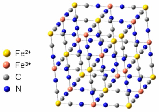
Figure 2.
Representation of Prussian blue structure. Adapted from Reference [7].
Among the first reports, several researchers evaluated the method of preparation [8], the structure [9,10], the oxidation state of the iron atoms, and its applications, and even after so many years there are doubts related to its structure.
Initially, PB was used as pigment [11], but later its high affinity for cations allowed it to be used for capturing thallium and cesium [12,13,14,15]. Electrochemical properties such as electrochromism [16] and the catalytic reduction of hydrogen peroxide [17] and molecular oxygen are also reported [18]. At present, the investigations using this compound have focused on electrochemical sensors [19], fuel cells, and sodium batteries [20,21], in addition to reports involving water splitting [22].
It is also expected that a change in the characteristics of the formed electroactive coordination polymers will occur when mixing a solution of PCF with a solution containing FeIII. The formation of ECP is observed (Figure 3), except in the case of the nitro ligand, due to its non-innocent character [23]. When the ligand is of the amino or aqua group, the ECP produced is quite similar to the traditional PB [5,10,24]. However, when the ligand is an N-heterocyclic, the ligand–metal charge transfer band (LMCT) of the N-heterocyclic ligand in the structure is still observed, as is the transition from the cyanide [15,25].
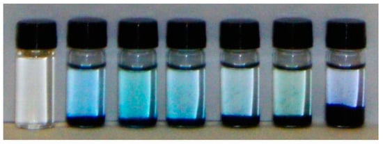
Figure 3.
Aqueous solutions of AP obtained from PCF. From left to right: nitro (NO), cyanide (CN−), aqua (H2O), amino (NH3), isonicotinate (C6H4NO2), pyrazine (C4H4N2), and methylpyrazinium (C5H7N2+).
Another interesting point is the contribution of the ligand in the formation of cavities in the PB structure [26]. The morphology and crystallinity of the resulting coordination polymers are directly influenced by the ligand associated therewith and can yield mesoporous materials [25,27,28].
With respect to the use of PCF in the production of electroactive coordination polymers, a new analysis can be performed in order to produce Prussian blue analogues and new coordination polymers; this is because the N fragment of the cyanide ligand has the ability to coordinate with other metal centers. The formation of traditional Prussian blue (PB) occurs when the metal involved in bonding is iron, but metals such as ruthenium can also be used.
The change in the metal center coordinated by the cyanide bridge has been well explored, as it also allows structural, spectroscopic, and electrochemical changes [4,29]. ECPs based on Prussian blue analogues are isostructural with respect to the traditional PB and can be crystalline or non-crystalline, depending on the form of obtention, in addition to the possibility of obtaining combinations of transition metal ions in multiple states of oxidation. They are also highly porous, being able to incorporate solvent molecules and alkali metal ions easily, but one problem with these compounds is that they do not have a defined stoichiometry.
The catalytic activity of the electroactive coordination polymers in coordination chemistry was explored some years ago [30]. The ECPs were used for the preparation of modified electrodes [31,32,33], for multiple applications relating to electrochemical sensors [34,35], and in applications involving electrochromic monitors [36]. In the field of electrocatalysis, several derivatives have been used for the oxidation or reduction of organic materials [37]. In oxidation catalysis [38], PB-modified electrodes have been developed to detect and quantify a variety of substrates, such as hydrazine [39], vitamins [40], amino acids [41], nucleobases [42], glucose [43], and other biologically relevant molecules [44]. It has also been reported that such derivatives could be used in the administration of drugs, controlled by electrophoresis [45]. In the field of energy applications, Prussian white was reported to be an efficient proton reduction catalyst for the evolution of hydrogen, exhibiting higher activity than noble metals like Pt [46,47]. Ruthenium purple (the common name given to the ECP obtained by the reaction between the [Ru(CN)6]4− complex and Fe3+ ion) also showed activity for the hydrogen evolution reaction [48]. Although they are presently intensively used as oxidation catalysts, the activity of ECPs for the oxygen evolution reaction was not established until 2013, when the electrocatalytic activity of K2xCo3-x([Fe(CN)6]2 (CoFePB) was observed [49]. At a neutral pH, this ECP exhibits kinetics comparable to those of metallic oxides, along with an unmatched long-term stability. CoFePB-modified electrodes maintain a persistent catalytic activity for weeks at neutral pH under ambient conditions.
ECPs appear to be a viable alternative to metal oxides in promoting the oxidation of water in artificial photosynthetic devices. They have competitive kinetics and better stability in neutral and acid media, they are obtained from earth-abundant metals, and they can be easily processed as powders, thin films, or nanoparticles using classical coordination chemistry tools. In addition, they are active at a neutral or acid pH without the need for additional electrolytes, since their stability occurs through the formed cyanide bridge, without the participation of oxo or hydroxyl groups in their structure.
Due to these characteristics, the modification of electrodes for electrocatalytic purposes, such as water oxidation or the electrochemical detection of biomolecules, is extremely attractive using this type of material. The relevant limitation is the stability of the film formed on the electrode’s surface after several cycles of film reduction; it has been reported that the films of AP slowly detach themselves from the electrode surface after several cycles of film reduction. This systematic effect occurs for all types of electrolytes. The decay of the current signal is due to the loss of ferric ion from the film [50].
Another limiting factor is the ease with which the film formed can transfer electrons to the electrode or to the solution. Several papers present studies discussing this factor mainly in the context of biological processes involving sensors, and artificial and electronic photosynthesis [51,52,53,54,55]. The focus on electron transfer kinetics has greatly increased in the field of molecular electronics (rectifiers, junctions, switches, transistors, sensors, etc.), leading to the portrayal of electrons transported between electrodes through molecular bridges [56,57].
In view of these characteristics, the compound Na3[Fe(CN)5(PZT)] (PZT = 2-Pyrazinylethanethiol, Figure 4) can be a very interesting alternative to study, because the presence of the N-heterocyclic ligand would stabilize the metal center in higher oxidation states, so long as it is possible to modify electrodes mainly with the thiol fragment. In addition, the formation of Prussian blue analogues can be facilitated by a possible coordination between the metal ion and the free nitrogen of the pyrazine ligand.
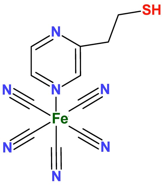
Figure 4.
Structure of the FePZT complex.
This study aims to investigate the synthesis, electrochemical characterization, and sensor application of the Na3[Fe(CN)5(PZT)] complex, a pentacyanidoferrate-based coordination compound incorporating 2-pyrazinylethanethiol as a ligand. One key objective is to explore its electrochemical behavior through cyclic voltammetry (CV) and electrochemical impedance spectroscopy (EIS), as used to modify glassy carbon and platinum electrodes. Furthermore, we seek to evaluate the electrocatalytic activity of the modified electrodes in hydrazine detection, assessing key analytical parameters such as sensitivity, detection limit, and linear response range. By doing so, this work aims to contribute to the development of advanced electrochemical sensors and provide new insights into the roles of N-heterocyclic ligands in coordination polymers, with potential applications in sensing and catalysis.
2. Results and Discussion
2.1. Development of Modified Electrodes with the Complex Na3[Fe(CN)5PZT]
To prove that the precursor complex FePZT has been synthesized, we obtained the electronic spectrum in the UV-Vis region and the vibrational spectrum for the spectroscopic characterization. The electrochemical behavior was studied by cyclic voltammetry.
The IR spectrum (Figure S1) of PZT exhibits the characteristic high-energy frequencies associated with the C–H stretching modes of the –CH2–CH2– group, and a broad band at 2540 cm–1 related to the S–H stretching vibration. In the FePZT, the FT-IR spectrum (Figure S1) presents two characteristic bands, at 2050 and 570 cm–1, which are associated with the vibrational modes of the CN and Fe–CN bonds. The S–H stretching mode can also be detected in the FTIR spectra, shifting from 2540 to 2470 cm–1 upon the N-coordination to the pentacyanidoferrate complex.
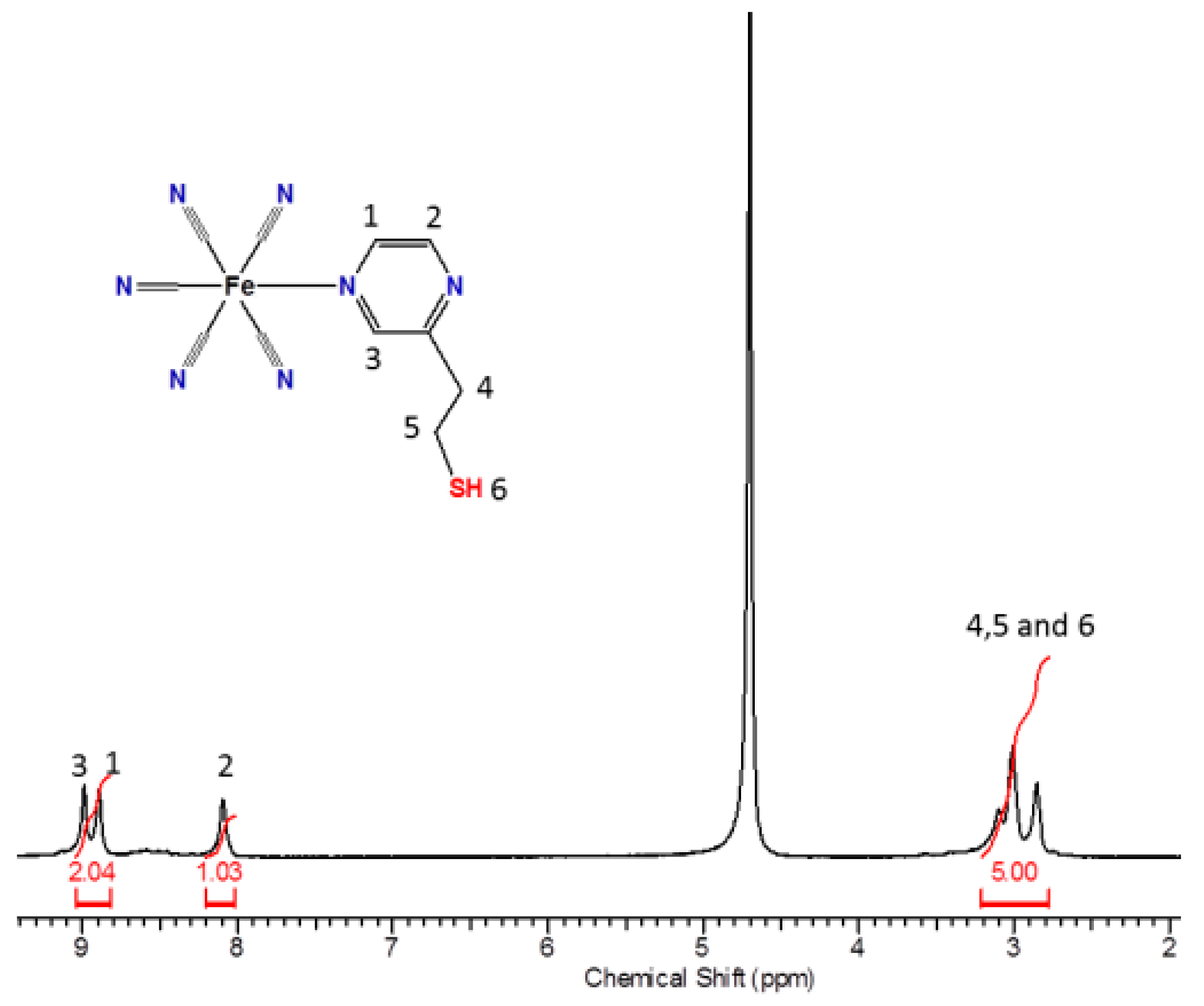
The 1H NMR spectrum (Figure 5) of the pentacyanidoferrate(II) complex in D2O exhibits the characteristic downfield shift of the signals of the adjacent aromatic protons (1 and 3) of the N-heterocycles coordinated to the [Fe(CN)5]3– moiety, changing from δ = 8.41 to 8.99 ppm for H1 and from δ = 8.41 to 8.89 ppm for the H3 signal, given the free ligand. Due to the distance involved, the H2 did not have a significant shift in the spectra.

Figure 5.
1H NMR spectrum of the complex FePZT in D2O.
The observed behavior of the aromatic protons in pentacyanidoferrate(II) N-heterocyclic complexes involves central contributions from the dπ→pπ back-bonding to the heterocyclic ligand and the opposing inductive effect, whereas for the α-protons the magnetic anisotropy due to the electron looping at the CN axis bond is most relevant [58]. Curiously, the thiol proton signal exhibits a pronounced change in the chemical shift with respect to that of the free PZT ligand, i.e., from δ = 1.43 to 3.33 ppm in the pentacyanidoferrate(II) complex. This effect can be ascribed to the magnetic anisotropy of the cyanide ligands, which produces a deshielding effect on the nuclei located perpendicular to this triple bond. As the thiol proton lies in a deshielding region, a large downfield shift is observed. Other evidence of the magnetic anisotropy of the cyanide ligands can be observed in the shape of the thiol proton peak. In fact, in D2O, the S–H signal of the free PZT ligand appears as a broad coalescent peak at δ = 1.43 ppm. After coordination to the pentacyanidoferrate(II) complex, this peak becomes narrow, at δ = 3.33 ppm, exhibiting a strong spin-decoupling effect, and removing the triplet feature observed in aprotic solvents.
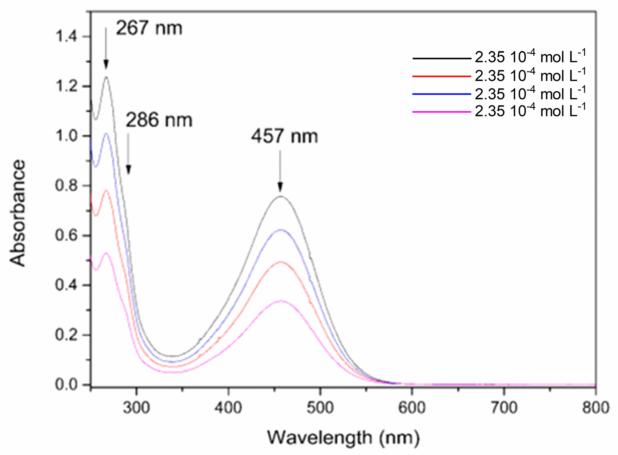
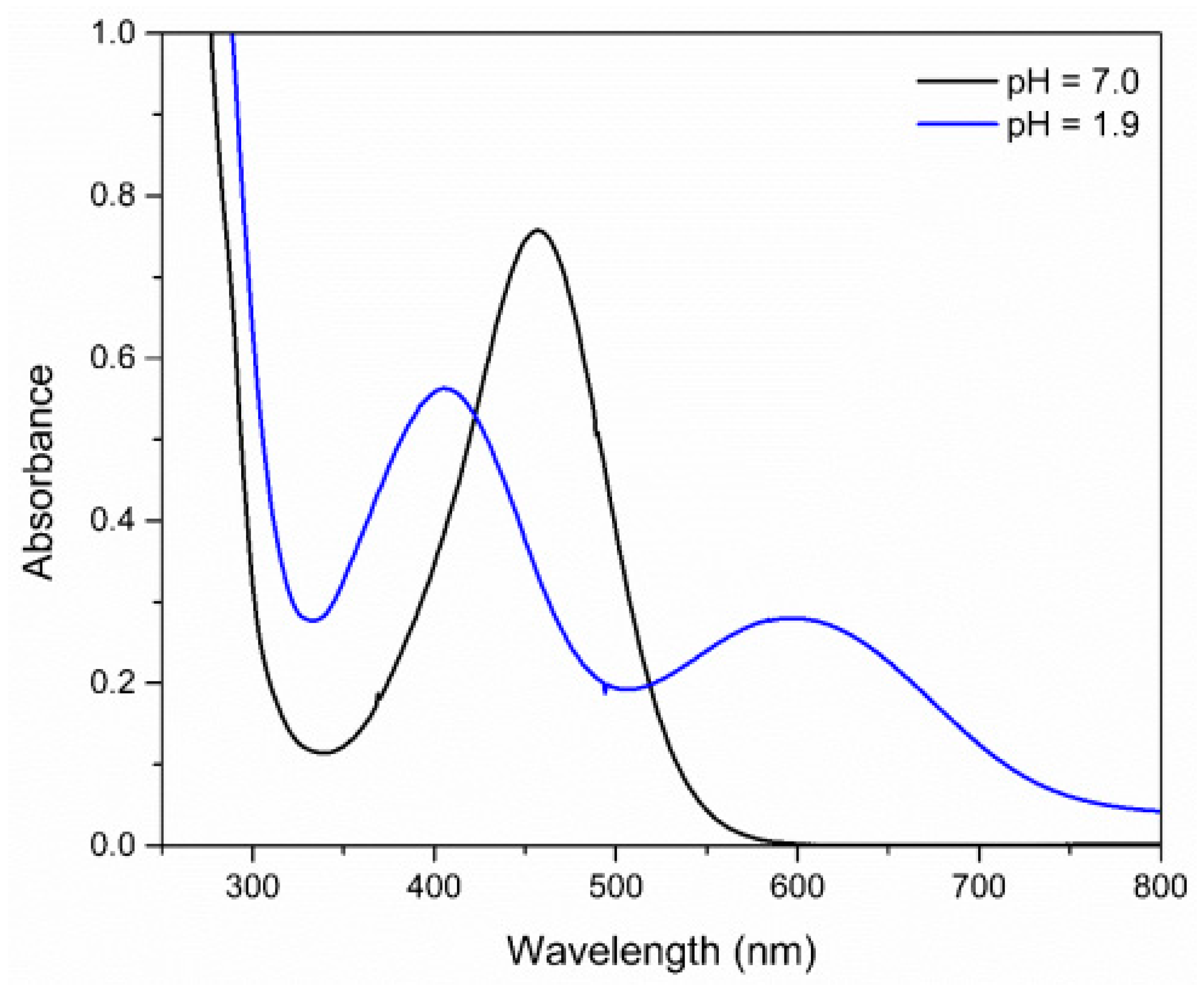
The absorption spectrum of the FePZT complex in the ultraviolet and visible region (Figure 6). In pH 7, it is possible to observe a band in the visible region assigned to the metal–ligand transitions (MLCT) at 457 nm. The ultraviolet transitions observed were assigned to the π-π* intraligand transitions of the PZT ligand, while the shoulder at 286 nm was attributed to a metal-to-ligand charge transfer (MLCT) transition involving the metal center and the cyanide ligands in the structure [59].
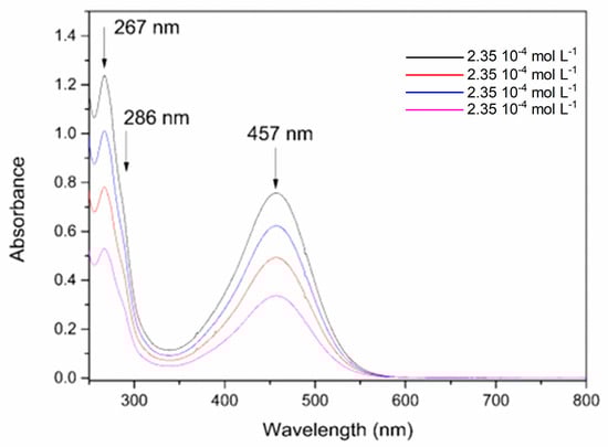
Figure 6.
Absorption spectra of the FePZT complex in water in different concentrations, pH = 7.
When the pH is lowered to the value of 1.9 a hypsochromic shift of the MLCT band is observed due to the protonation of the complex. The hypochromic displacement of the absorption bands in the UV–Vis region is an indication that the protonation influences the energy of the orbitals, indicating that the ligand in the coordination sphere, when undergoing protonation, significantly affects the energy of the molecular orbitals, predominantly those of the metal, and more specifically, the HOMO orbital of the complex (Figure 7) [60].
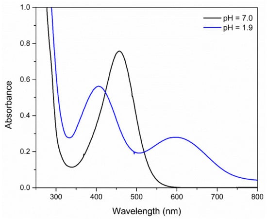
Figure 7.
Absorption spectra of FePZT complex in water, in pH = 1.9 and pH = 7.0.
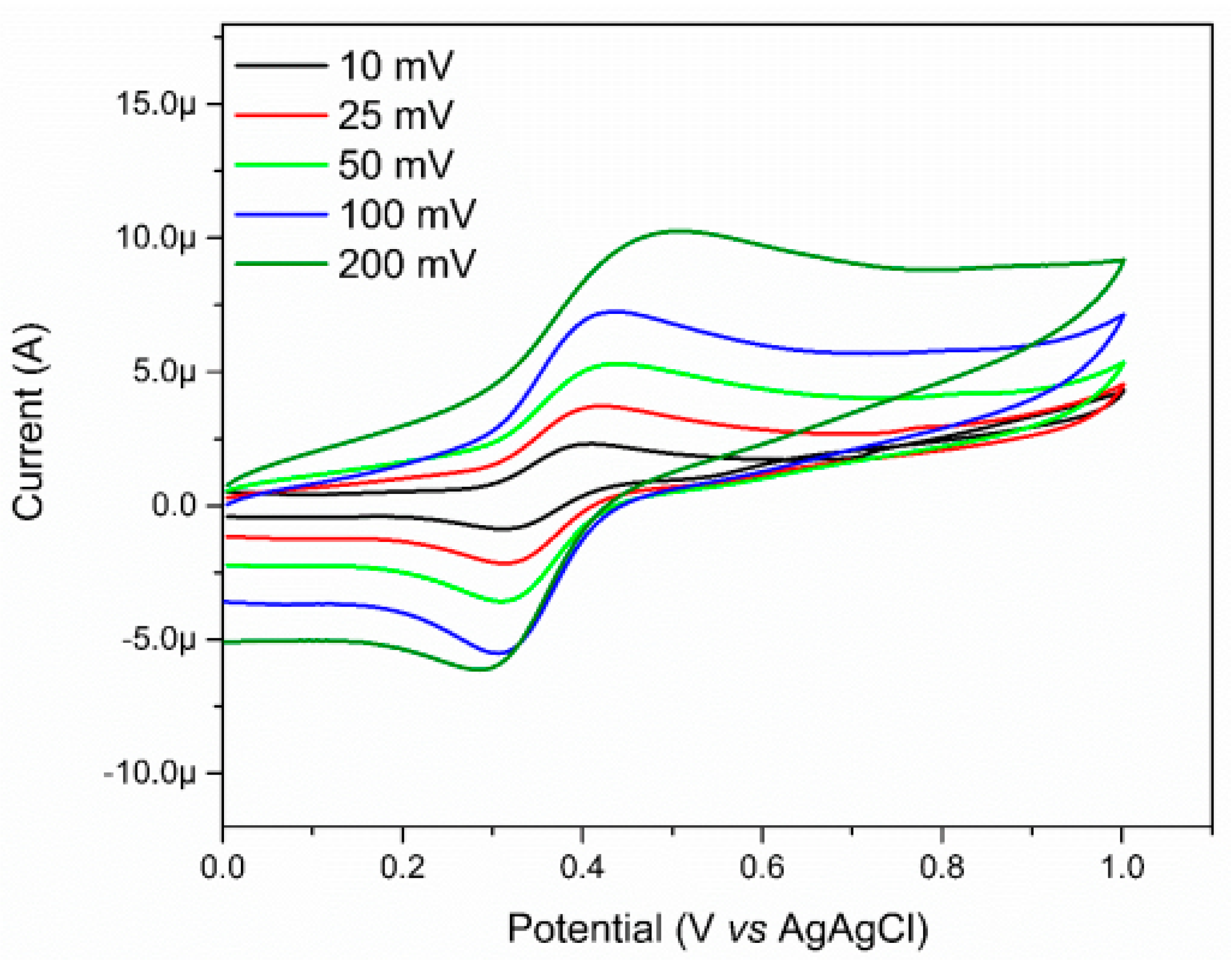
In addition to the spectroscopic study, the electrochemical nature of the complex was also evaluated through the cyclic voltammetry (Figure 8). The electrochemical studies relating to the complex were carried out in water, and by using potassium chloride (KCl) as support electrolyte, a glassy carbon electrode as working electrode, a platinum counter electrode, and the Ag/AgCl as reference electrode. In the voltammogram, it is possible to observe a quasi-reversible wave attributed to the oxidation process of the Fe(II)/Fe(III) metal center at 0.45 V vs. Ag/AgCl. Compared to the value of the [Fe(CN)5(NH3)]3− complex, an increase in the oxidation potential of the metal center (from 0.14 V vs. Ag/AgCl for the FeNH3 complex to 0.45 V vs. Ag/AgCl for the FePZT complex) [61] is observed due to the π acceptor nature of the N-heterocyclic ligand, which lowers the electron density in the center of metal, making the oxidation of the same more difficult.
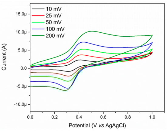
Figure 8.
Voltammograms of FePZT in water, using potassium chloride (KCl) as support electrolyte, glassy carbon electrode as working electrode, one counter platinum electrode, and a reference electrode of Ag/AgCl. Potential range: 0.01 V–1.0 V vs. Ag/AgCl.
Due to the various species that the FePZT complex may present, depending on the pH of the solution, the pKa values of the complex and their electrochemical behavior were determined by varying the pH values (Figure S2). It has been noted that the complex has two pKa values. At first glance, we can assign the first pKa value (3.0) to the protonation of the pyrazine ligand, but when comparing analogous complexes, such as [Fe(CN)5(py)]4−, whose ligands have no protonation sites, the formation of a protonated species is still observed. Toma et al. studied a series of complexes of molecular formula [Fe(CN)5(L)]n− (L = picoline, pyridine, 4- amide-pyridine, pyrazine, pyridyl-pyrazine, and methyl-pyrazine), and was able to observe a trend in the pKa values obtained in an acid medium, one which decreases with the reduction in charge of the transfer charge energy of these complexes. This fact can be explained by the reduction of the cyanide basicity, which is due to the electron-withdrawing character of the n-heterocyclic ligand. The second pKa value obtained in the complex FePZT is attributed to the deprotonation of the thiol group of the PZT ligand (pKa = 9.75).
A Pourbaix correlation diagram is presented in Figure 9. These diagrams are used in many fields, such as corrosion science and geochemistry [62]. The pH–potential diagrams for simple transition metal ions are complex, involving multiple protons and electron transfer processes. At a pH below 3.0, the complex presents three different redox processes: the blue line designates the Fe3+/Fe2+ process; the red line, a shoulder at this process; and the pink line the reduction of the PZT ligand. The slopes of each oxidative process line below pH 3 are approximately equal to 59 mV, which is characteristic of a one-electron one-proton coupled process. Above a pH of 3.0, the deprotonation of the CN ligand trans of the PZT ligand occurs, and the process is no longer pH dependent (Figure S3).
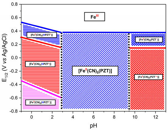
Figure 9.
This Pourbaix diagram contains the species possibly formed in each region of the FePZT complex. The symbol * (PZT*) represents a radical species generated through the reduction process. The charges indicated in the diagram correspond to electron transfer events: a negative sign (−) denotes the addition of an electron during reduction, while a positive sign (+) represents oxidation and the loss of an electron. Additionally, the protonation process of the pyrazine ligand is highlighted by the blue “H” symbol, and the oxidation state of the iron center is indicated in red above its symbol in the structure.
After studying the spectroscopic and electrochemical properties of the complex, we started the evaluation of the electrode-modification capacity of this complex. Thus, electrochemical impedance spectroscopy analysis was performed using the [Ru(NH3)6]3+ complex as a probe. The use of this complex instead of the traditional hexacyanoferrate can be explained as an attempt to avoid interference in the analysis, such as the formation of Prussian blue on the surface of the electrode, with the reduction of the probe; accordingly, the electrochemical process on the surface of the electrode can only be attributed to the transfer of electrons, without any parallel interactions occurring between the probe and the modified electrode.
The electrode that is most fitting for this evaluation of the modification is the gold electrode, due to its high affinity with softer ligands like sulfur. The study was based on the time of formation of the S-Au bond, for which the gold electrode was immersed in a solution of the Fe-PZT complex at various times (Figure S4).
The data obtained were then adjusted to an electric circuit that would represent schematically the behavior of the modification. In this way the circuit chosen was the one proposed by Randles (Figure S5). In this scheme, Rs would be the resistance to electronic transfer of solvent, Rct the charge transfer resistance between the electrode and the solution, Cdl the electric double layer capacitance, and the element W would represent an infinite diffusional process.
As seen in Table 1, the charge transfer resistance increases as the immersion time is raised, until it reaches a value that does not suffer as much variation; this shows that the electrode has reached a saturated state as to the molecules on its surface. The inverse pattern can be observed when analyzing the CPE value of the material (Y0): the clean electrode presents a high capacitance value, demonstrating that its surface is more homogeneous in relation to the accumulation of charges; as the FePZT molecules are bound on its surface, the gold electrode now has a greater variation in charge, causing the formed electric double layer to be not uniform.

Table 1.
Values obtained from the fitting of the equivalent electrical circuit (EEC) to the experimental data. The “3600 dry” condition refers to the electrode measured after 3600 s, followed by drying under vacuum for 12 h before analysis.
Another way of evaluating the impedance data is by analyzing the Bode graph, which can be seen in Figures S6 and S7. With the increased immersion time of the electrode, an increase in the value of the phase angle can be noted; in addition, it is now possible to observe a slight increase in the charge transfer resistance of the material. It is possible to determine that the complete adsorption of the material on the surface of the electrode happens close to 600 s.
Based on the data, we can assume that the Au-FePZT electrode can be used for the sensing of molecules, but when analyzing the electrochemical behavior of the electrode after 12 h in the desiccator, we see that a change occurs in the structure of the material. The hypothesis that we advance to explain this evidence would be that the FePZT complex would oxidize the metal surface, thus forming Au3+; this species then coordinates rapidly to the cyanide nitrogen, thus forming an analogue of Prussian blue containing the gold in its structure. With the formation of the new film on the surface of the electrode, we observe the increased values associated with the resistance to charge transfer [63].
So, how to avoid this situation? Our first idea was to replace the gold electrode with a more stable electrode under these conditions, so the platinum electrode was tested for the formation of modified electrodes, but now involving the coordination polymers based on Prussian blue analogues FeFePZT, RuFePZT, and RuFeCN.
2.2. Synthesis, Characterization, and Electrochemical Properties of Ruthenium-Containing Prussian Blue Analogues Derived from the Na3[Fe(CN)5(PZT)] Complex
The synthesis of the ECPs is direct when the reaction occurs between the hexacyanoferrate or pentacyanidoferrate and the metals like Fe3+, Cu2+, and Co3+, basically so that these compounds react and form ECPs. When the metal ion is exchanged for Ru3+, the reaction does not occur spontaneously, and more energetic conditions are required. For this reason, the autoclave system was used to favor the inclusion of this metal in the structure and facilitate the reaction.
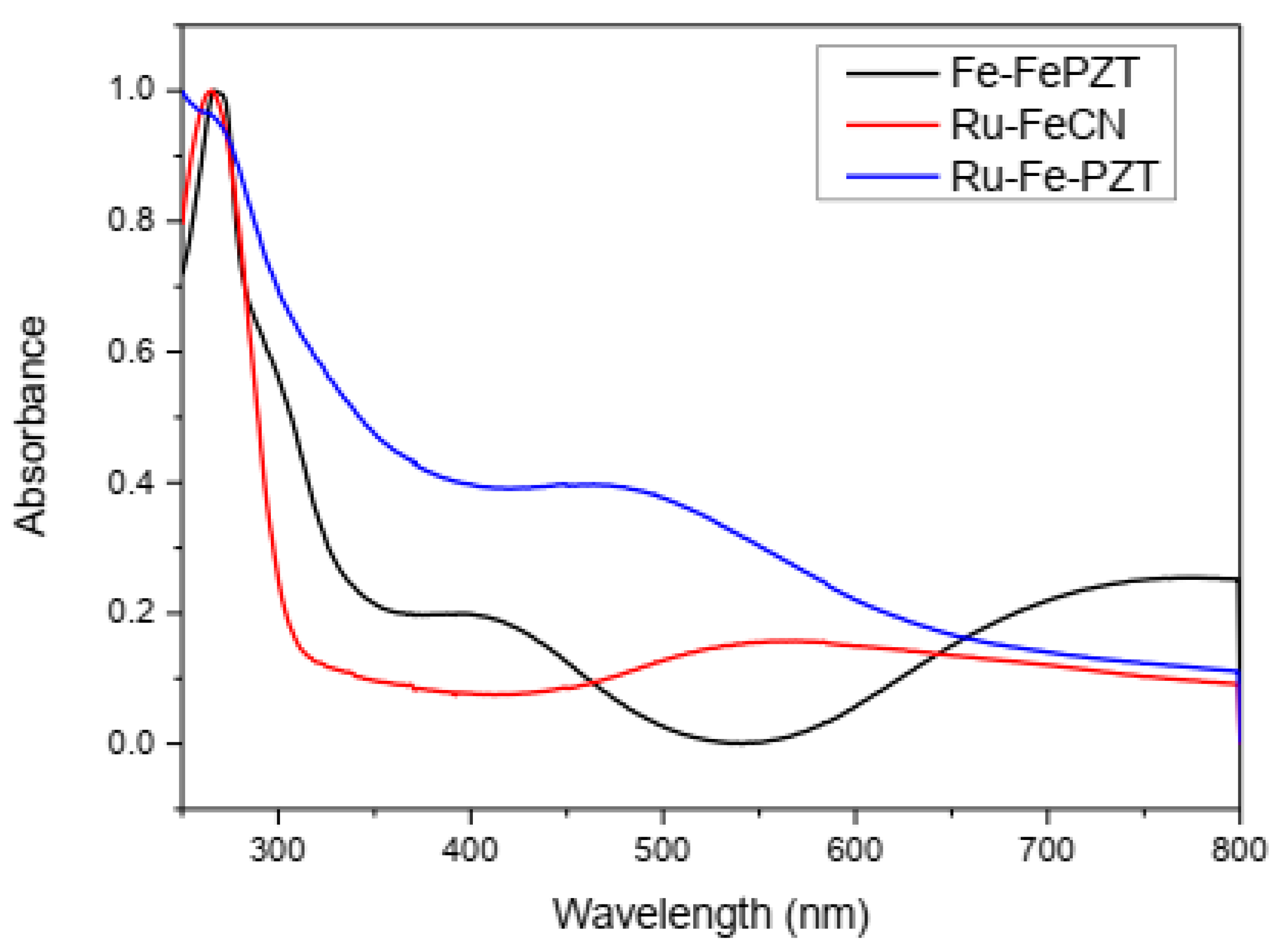
Due to the charge transfer between the metallic centers, these compounds show intense colorations and characteristic electronic spectra (Figure 10). The ECP RuFeCN presents a structural configuration similar to ruthenium purple (Fe4[Ru(CN)6], and therefore the observed energy for the transition of intervalence for both compounds is located near the same wavelength (550 nm). When the ECP formation starts from the FePZT complex, the MLCT transition band, in the area of 400 nm and 500 nm, is observed for both the ruthenium compound and the iron compound, respectively. In addition to this transition, the formation of Fe-CN-Fe and Fe-CN-Ru species is confirmed by the bands of 525 nm and 550 nm, respectively.
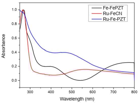
Figure 10.
Spectra in the ultraviolet region and visible region for ECP FeFePZT, RuFePZT, and RuFeCN in water.
The infrared spectra of the synthesized ECPs (Figure S8) showed the characteristic bands relating to binding of the cyanide ligands and solvation of the water molecules. The bands assigned to the CN groups are observed in the 1800–2200 cm−1 region. It is possible to observe that, unlike the FeFePZT compound, ruthenium-containing ECPs had a shoulder in the 2000 to 1800 cm−1 range, which was attributed to CN stretching close to ruthenium. In addition to these normal modes of vibration, some bands are observed referring to the ligand in the range of 1250–1000 cm−1.
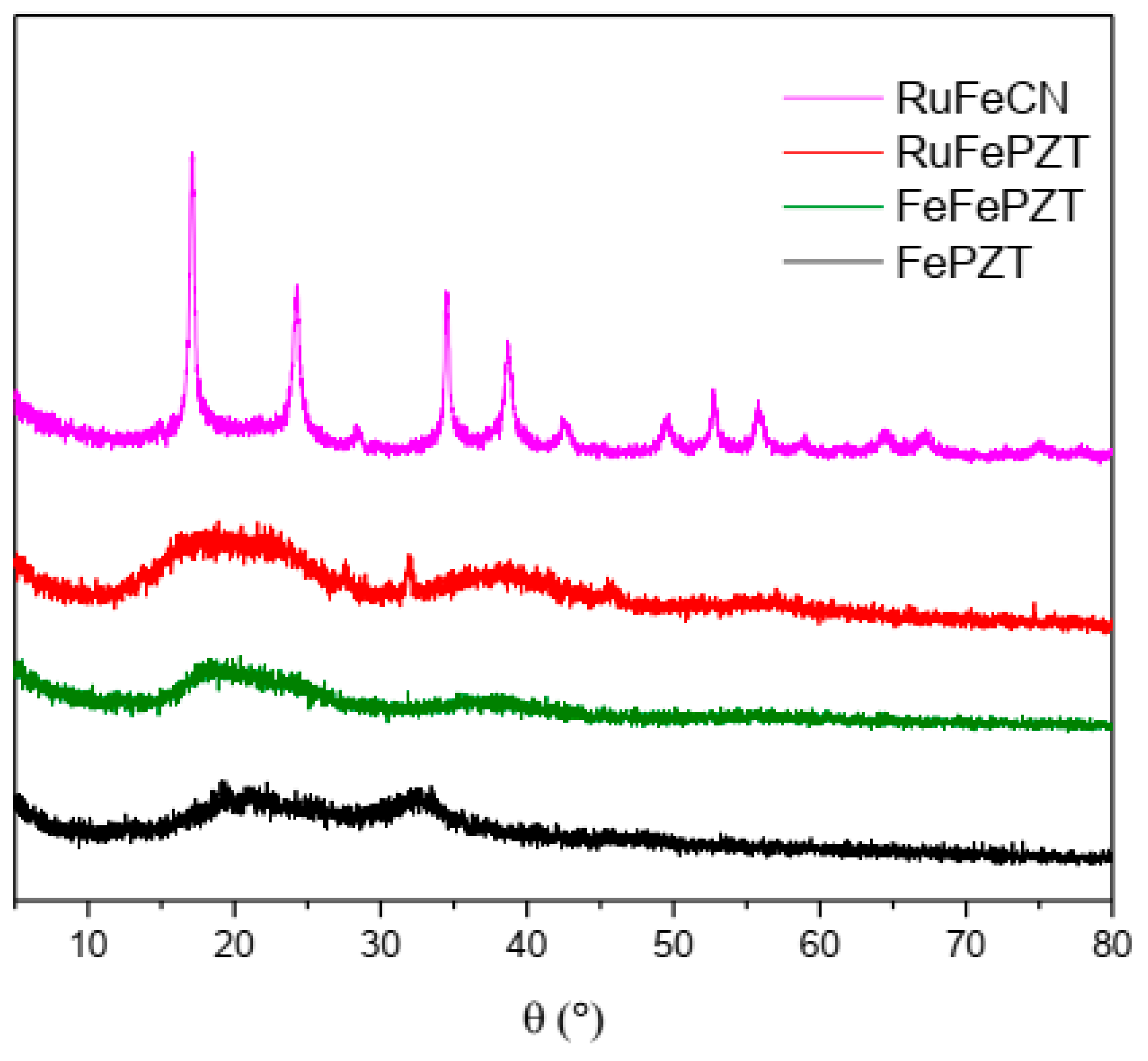
The ECPs exhibit structures based on the cubic structure M4[M(CN)6] 3H2O, in which the octahedral complexes [M(CN)6]4− are linked by octahedrally coordinated M3+ ions; hence, the X-ray diffraction pattern for this class of compounds is similar, as can be observed in Figure 11. When the exchange of the CN ligand occurs by the PZT ligand, a change in the crystallinity of these compounds is observed, making them more amorphous; while RuFeCN has defined peaks, both FeFePZT and RuFePZT show two wide peaks. However, it is possible to see a relationship between the RuFeCN peaks and the broad peaks of FeFePZT and RuFePZT, which means that the structures of both are similar. The difference is that the amplitudes of the peaks indicate a random atomic distribution, that is, a short-range atomic distribution (Figure 11)
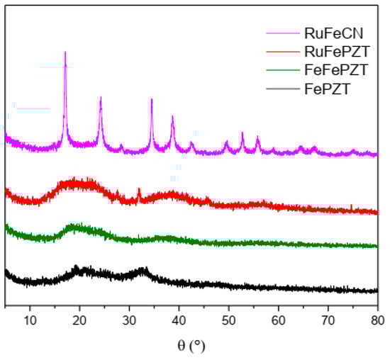
Figure 11.
X-ray powder diffractograms of the FePZT, FeFePZT, RuFePZT, and RuFeCN.
To improve the adhesion of ECPs on a platinum electrode the film formed was submitted to the potential of 1.5 V vs. Ag/AgCl. In this potential, the surface of the platinum electrode is converted to a monolayer of PtO and Pt(OH)2 [64] that can coordinate on the nitrogen or sulfur of the PZT and CN ligand.
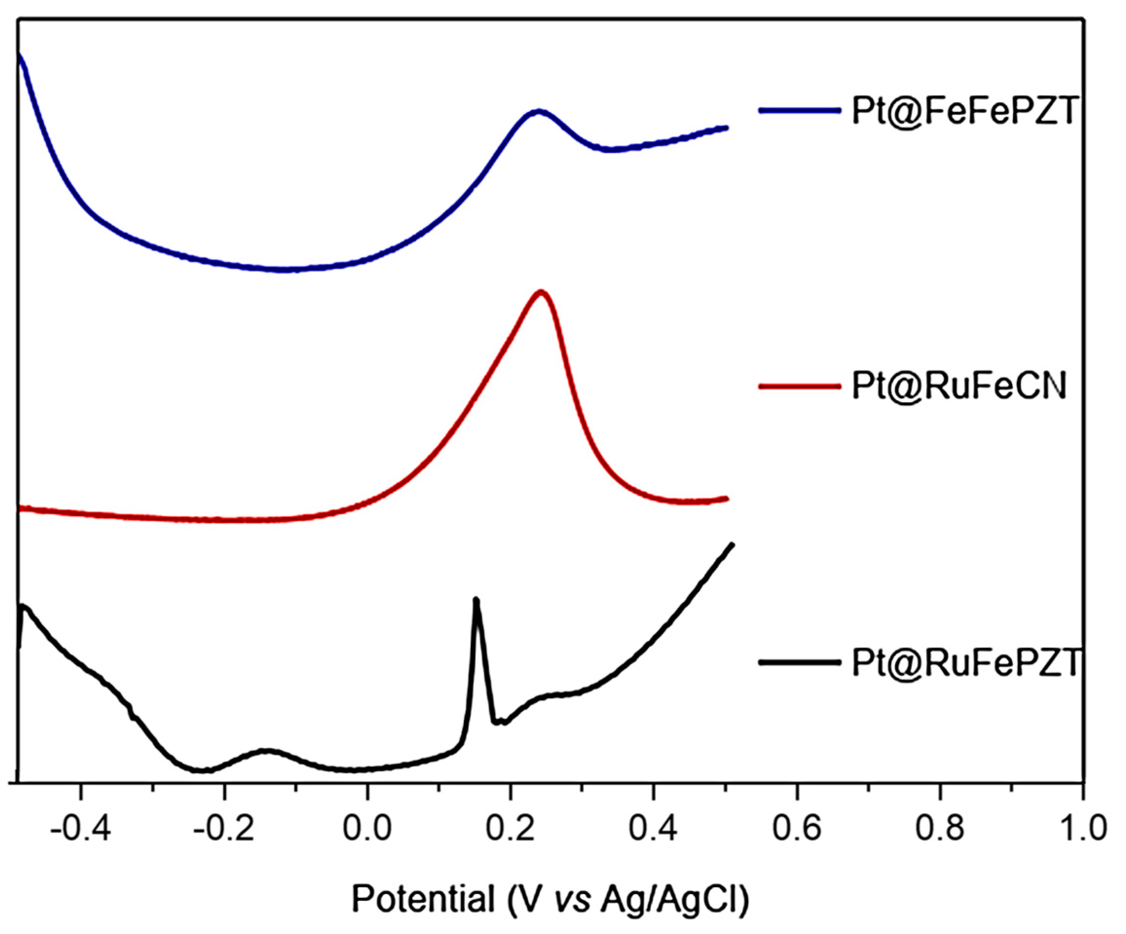
The formation of ECP was started by the formation of films on the platinum electrodes (Pt@FeFePZT-modified platinum electrode with ECP FeFePZT; Pt@RuFePZT-modified platinum electrode modified with ECP RuFePZT; and Pt@RuFeCN-modified platinum electrode with ECP RuFeCN). Due to the amount of film deposited on the electrode, the electrochemical study was performed using the square-wave voltammetry technique (Figure 12). Analyzing the compound with the simplest electrochemical profile (Pt@RuFeCN), we can observe only a 0.2 V vs. Ag/AgCl process attributed to the Fe2+/Fe3+ oxidation. The Ru2+/Ru3+ process was not observed in this working range, and the same profile was observed for the RuFePZT electrode.
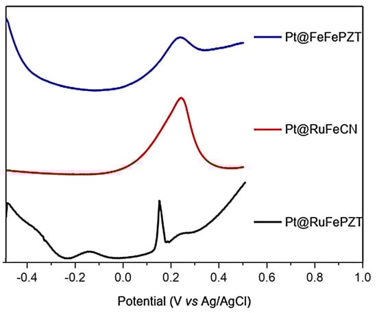
Figure 12.
Square-wave voltammetry for the Pt@FeFePZT, Pt@RuFePZT, and Pt@RuFeCN electrodes: frequency of 25 Hz, with amplitude of 20 mV; counter platinum electrode, and a reference electrode of Ag/AgCl.
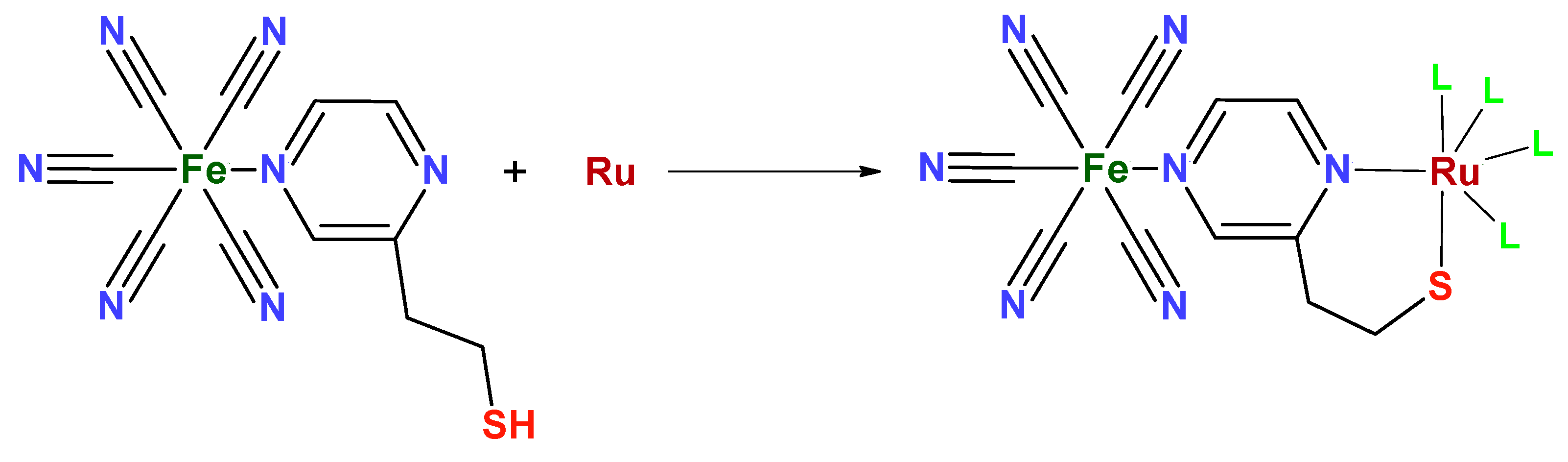
The Pt@RuFePZT electrode presents the greatest difference in its electrochemical behavior when compared to the others. We can observe the same wave in the 0.2 V vs. Ag/AgCl found in the other modified electrodes and attributed to Fe2+/Fe3+ oxidation. The differential of this electrode can be seen in negative potentials in which the process is observed at −0.17 V vs. Ag/AgCl. Perhaps during complex formation, due to high temperatures and high pressure conditions, Run+ ions complex with the other end of the PZT ligand (Figure 13). This coordination would lead to the formation of FePZT-Run+ fragments. Therefore, the observed wave at −0.17 V vs. Ag/AgCl can be attributed to the Ru2+/Ru3+ process.
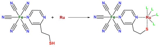
Figure 13.
Structure proposed for the reaction between the FePZT and Run+ complex. The L ligands can be both the solvent (water) and other FePZT complexes.
Considering how the structural differences alter the film formed (mainly with respect to pore size) the determination of the electroactive area of these electrodes can be of great help in understanding this fact. In general, the area of the electrodes was determined by cyclic voltammetry, using an electrochemical probe ([Fe(CN)6]4− [(Fe(CN)6]3− and treating the data obtained using Equation (1).
where n is the number of electrons involved in the process, is the diffusion coefficient of the electrochemical probe, the concentration of the species, and is the scanning speed. The obtained data are shown in Table 2. Compared with the clean platinum electrode, the electroactive areas of the obtained electrodes are twice as large; this can be explained by the presence of pores and roughness in the film formed.
Table 2.
Calculation of the electrochemically active area of the electrodes under study, where v determines the scan rate and the obtained area.
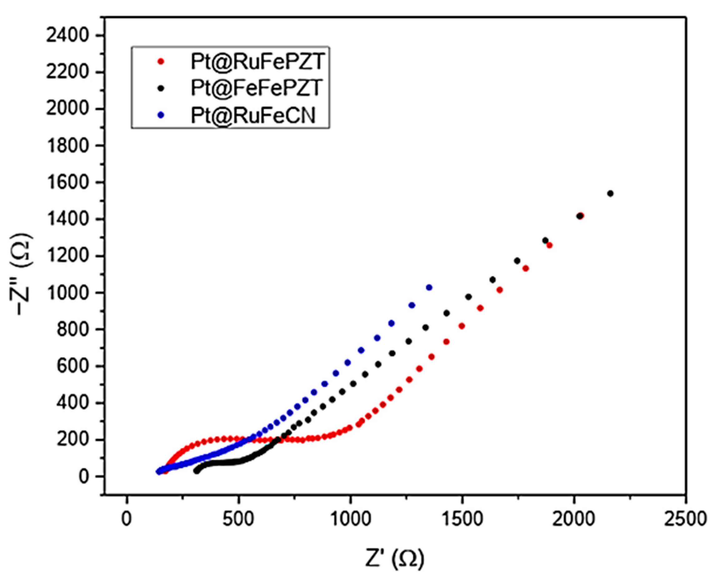
Considering that the film formed acts as a second interface between the electrode and the solution, the electrochemical behavior of the modified electrodes was analyzed by electrochemical impedance spectroscopy (EIS). EIS measures the impedance and allows the determination of Z (the system is determined as a function of frequency, so the chemical reaction that occurs on the surface of the electrode can be compared with an equivalent electrochemical circuit and each step can be related to an electrochemical element). The Randles circuit is one of the simplest models used to analyze the reaction that occurs at the electrode’s surface.
Figure 14 shows the Nyquist spectra for the electrodes obtained in this work. In this graph the presence of two distinct regions is clear: the first is in the higher frequencies, where the electron transfer process can be observed forming a semicircle; and the second is at low frequencies, where the mass transfer process is what determines the spectrum profile, generating a line with a slope close to 45°.
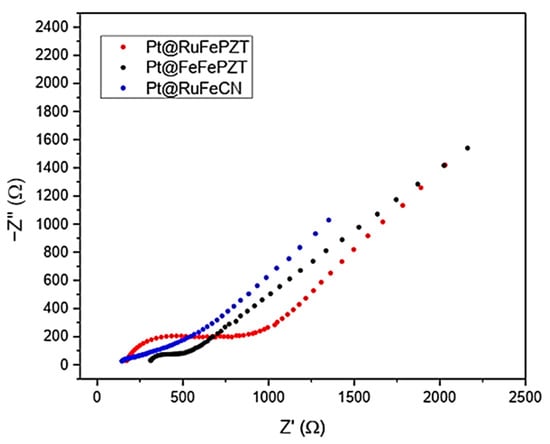
Figure 14.
Nyquist plot for the Pt@FeFePZT, Pt@RuFePZT, and Pt@RuFeCN electrodes in the range of 5000 to 0.05 Hz, with amplitude of 10 mV.
By adjusting the data obtained experimentally with the equivalent Randles circuit, we can obtain the values for each element of the circuit (Table 3). It is interesting to note that the electrodes Pt@RuFeCN and Pt@RuFePZT showed the highest value of charge transfer resistance, which may be related to the low uniformity of the films formed. It is also possible to obtain information about the roughness of the film formed by using the CPE n values, which describe how close this element is to a real capacitor (for n = 1 the CPE behaves like a real capacitor).
Table 3.
Values obtained through adjustments between the experimental data and the Randles equivalent circuit.
The evaluation of the heterogeneous electron transfer rate constant () was performed using three methods. The first two methods, the Nicholson [65] and Kochi [66] methods, are based on the peak separation generated by the electrode modification involving a redox probe, and the third method is Gileadi [67]. The Nicholson method is often used to determine the standard heterogeneous electron transfer rate constant ) by relating it to a dimensionless kinetic parameter (Equation (2)).
where is the diffusion of the redox probe, the number of electrons involved, the Faraday constant, the gas constant, the temperature, and the scan rate. The dimensionless parameter can be obtained in the literature; for this, the values of Ψ are tabulated as a function of the separation of peaks [65].
The second method was described by Kochi and Klinger. This method also depends on the peak separation (Equation (3)). is the electron transfer coefficient; this was considered to be 0.5 for the redox probe [Fe(CN)6]4−/[Fe(CN)6]3−.
The third method is known as the Gileadi [67] method, and does not require peak separation to determine the value of . This method is based on determining the critical scan speed at which the electrode reaction changes from reversible to irreversible. Then, by following Equation (4) one can calculate the value of .
The electron transfer velocity constants are noticeably slower for the modified electrodes compared to the unmodified electrodes (the value of on the platinum electrode for the redox probe was 8.4 cm s−1), showing that the transfer of electrons is hampered (Table 4).
Table 4.
The values obtained by the methods of Kochi, Nicholson, and Gileadi for the three modified electrodes.
The Pt@FeFePZT electrode presented a good stability in an acidic medium. The low pH provides protons that can penetrate into the defects of the structures [68]. Thus, decreasing the charge density around the iron ions increases the oxidation potential of FeNC. Additionally, the cycling step protects the Fe-NC from the anions, changing the oxidation state of this metal, and consecutively causing a structural rearrangement in the film formed.
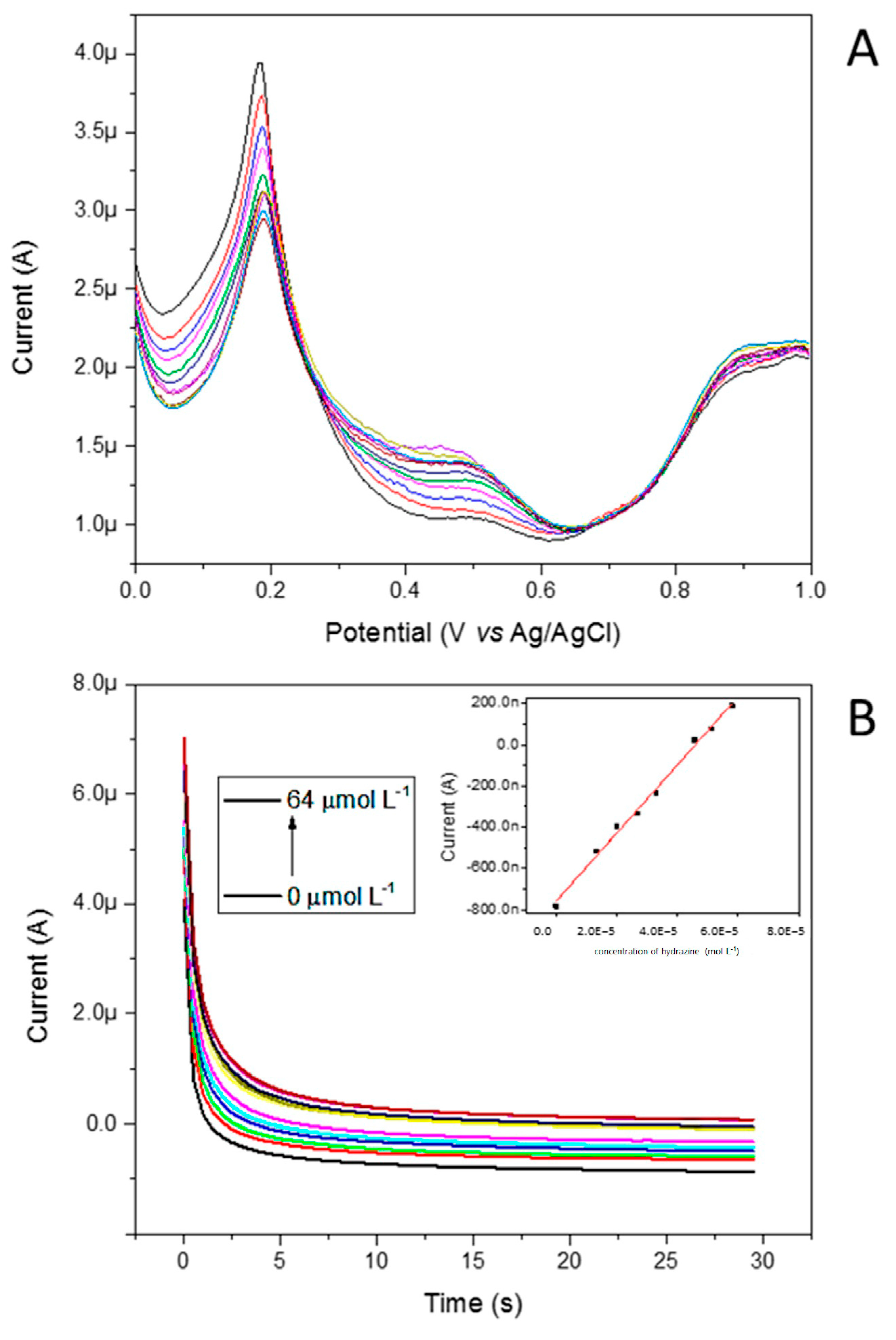
The next step of the characterization studies was focused on the electrocatalytic activity of the redox mediator toward hydrazine. The oxidation peak currents in various concentrations of hydrazine for the Pt@FeFePZT were recorded by differential pulse voltammetry (DPV) in static solutions and chronoamperometry. Figure 15A illustrates the effects of various hydrazine concentrations on the DPVs at the Pt@FeFePZT. Well-defined voltammograms were obtained.

Figure 15.
(A) Effect of various hydrazine concentrations on the DPVs at the Pt@FeFePZT, showing well-defined voltammograms. (B) Chronoamperograms at 0.35 V vs. Ag/AgCl obtained for Pt@FeFePZT in water, using potassium chloride (KCl) as support electrolyte, a platinum wire as counter electrode, and a reference electrode of Ag/AgCl. In the graphs, the concentration of hydrazine was varied from 0 to 64 mmol L−1.
The height of the anodic peak in 0.47 V vs. Ag/AgCl increased with increasing concentrations; in contrast, the peak referent to the Fe2+/Fe3+ redox process begins to decrease due to the reductive property of hydrazine. Figure 15B illustrates the chronoamperometric response of the Pt@FeFePZT in HCl 0.10 mol L−1 and KCl 0.10 mol L−1 after successive additions of hydrazine. As can be seen from Figure 15B (insert), the proposed sensor showed a linear response, ranging from 5 up to 64 µmol L−1. The detection limit was 7.38 × 10⁻⁶ M. According to these results, the linear response obtained at low concentrations of hydrazine can be used to develop a hydrazine sensor. The comparisons with previously reported chemically modified electrodes for the determination of hydrazine is listed in Table 5 As can be seen, the designed Pt@FeFePZT exhibited a relatively low detection limit.
Table 5.
Comparisons of the responses of some hydrazine sensors constructed based on different modified electrodes.
3. Materials and Methods
3.1. Experimental Details
All chemicals were used as received. The electronic spectrum UV–Vis was obtained using an Agilent 8453 diode array spectrometer by Agilent Technologies, Santa Clara, CA, USA. A quartz cuvette of 1.0 cm path length at 23 °C was used in the experiment. Electrochemical data were obtained using an Autolab PGSTAT32N potentiostat Metrohm Autolab, Utrecht, The Netherlands. Electrochemical experiments were performed using a glass cell and conventional electrodes. The reference electrode was Ag/AgCl KCl in 3 mol L−1 (E° = +0.210 vs. SHE). The working electrode used was Pt and the auxiliary electrode was a Pt wire.
3.2. Synthesis of the Na3[Fe(CN)5(PZT)] Complex
The Na3[Fe(CN)5(PZT)] complex was synthesized following a procedure from the literature, with modifications. Initially, 0.2 g of aminopentacyanidoferrate was dissolved in 1 mL of deionized water. To this solution, 1 mL of a 2-pyrazinylethanethiol (PZT) ligand solution, prepared in a fivefold molar excess, was added. The mixture was then cooled in an ice bath and stirred in the dark for 30 min to ensure complete reaction.
Following the reaction, 1.0 g of sodium iodide (NaI) was added to the solution to facilitate the precipitation of the complex. Ethanol (30 mL) was then gradually introduced under continuous stirring, which resulted in the formation of a precipitate. The solid complex was separated by vacuum filtration, washed with ethanol, and redissolved in deionized water. The procedure of precipitation with ethanol was repeated to purify the complex. The purified solid was then dried under vacuum in a desiccator until a constant weight was achieved, yielding a fine powder of the Na3[Fe(CN)5(PZT)] complex.
3.3. Electrochemical Studies and Electrode Modification
Electrochemical experiments were conducted using a three-electrode system consisting of a glassy carbon electrode (GCE) or a platinum electrode as the working electrode, a platinum wire as the counter electrode, and an Ag/AgCl electrode as the reference.
The working electrode was polished sequentially with alumina suspensions of 1.0, 0.5, and 0.3 μm to obtain a smooth surface. Following polishing, the electrode was sonicated in ethanol and deionized water to remove any residual alumina particles and organic contaminants. Cyclic voltammetry measurements were conducted for the complex in solution (5 mM in KCl 0.1 M), focusing on the specific potential ranges of each redox process to better define and highlight their characteristics.
To modify the working electrode, a suspension of the synthesized Na3[Fe(CN)5(PZT)] complex (1.0 g mL−1) was prepared and 10 μL of this suspension was drop-cast onto the surface of the cleaned electrode. The modified electrode was then left to dry in a desiccator under vacuum at room temperature for 12 h, ensuring strong adhesion of the complex to the electrode surface.
Electrochemical impedance spectroscopy was performed using a conventional three-electrode system, consisting of a platinum or glassy carbon working electrode, a platinum wire counter electrode, and an Ag/AgCl reference electrode. The measurements were carried out in an aqueous solution containing 0.1 M of potassium chloride (KCl) as the supporting electrolyte. The impedance spectra were recorded over a frequency range of 5000 to 0.05 Hz, with an applied sinusoidal potential perturbation of 10 mV amplitude.
To prevent interference from the formation of Prussian blue on the electrode surface, [Ru(NH3)6]3+ was used as the redox probe instead of hexacyanoferrate, applying a potential of 0.25 V vs. Ag/AgCl. The obtained impedance data were fitted using the Randles equivalent circuit. All measurements were conducted under identical conditions to ensure consistency and facilitate direct comparison between the different electrode materials.
3.4. Application in Hydrazine Sensing
The modified electrode was evaluated for its electrocatalytic activity towards the oxidation of hydrazine. The electrochemical response was measured using differential pulse voltammetry (DPV) in the presence of varying concentrations of hydrazine. The performance of the sensor was quantified by assessing the detection limit, linear response range, and sensitivity.
4. Conclusions
In this study, the Na3[Fe(CN)5(PZT)] complex was successfully synthesized and electrochemically characterized, demonstrating its potential as an effective electrocatalyst for hydrazine oxidation. The modified electrodes exhibited enhanced charge transfer properties and catalytic activity, as confirmed through cyclic voltammetry, differential pulse voltammetry, and electrochemical impedance spectroscopy. The electrochemical results revealed a low detection limit (7.38 × 10⁻⁶ M), a wide linear range (5–64 µmol L−1), and high sensitivity, positioning this system as a promising candidate for hydrazine sensing applications.
Beyond the demonstrated sensing capabilities, this work paves the way for future advancements in Prussian blue-analogue-based electrochemical systems. One potential direction is the further optimization of the electrode architecture to enhance long-term stability and improve selectivity for hydrazine detection in complex matrices. Additionally, the integration of Na3[Fe(CN)5(PZT)] with nanostructured materials, such as carbon-based supports or metal nanoparticles, could further enhance electron transfer efficiency and electrocatalytic performance.
Moreover, given the versatility of Prussian blue analogues, this system could be explored for broader applications, including energy storage, electrocatalysis in fuel cells, and water oxidation processes. Future studies could also investigate the tunable electronic properties of the complex by modifying the ligand environment or incorporating different metal centers, expanding its utility in molecular electronics and artificial photosynthesis.
Overall, this research establishes Na3[Fe(CN)5(PZT)] as a promising electroactive material with applications beyond hydrazine detection, contributing to the ongoing development of advanced coordination-based electrochemical platforms.
Supplementary Materials
The following supporting information can be downloaded at: https://www.mdpi.com/article/10.3390/inorganics13030085/s1. Figure S1: Vibrational spectrum of the FePZT complex obtained in KBr pellet. Figure S2: Titration curve of the FePZT complex. Figure S3: The chemical equilibria involved in the processes observed during the titration of the FePZT complex primarily involve protonation-deprotonation. Figure S4: Nyquist plot of impedance spectra of the modified electrode for different times of immersion in 0.1 mol L−1 PBS ph 7.0 at 298 K using [Ru(NH3)6]Cl3 (5.0 × 10⁻⁴ mol L−1) as probe, with applied potential of −0.14 V vs. Ag/AgCl. Figure S5: Modified Randles equivalent circuit. Figure S6: Bode impedance plot for several immersion times of the gold electrode in an FePZT solution. Representation of the Bode phase plot in hollow circles, and Bode impedance graph in full circles. Figure S7: Bode impedance plot of several immersion times for the gold electrode in an FePZT solution. Representation of the Bode phase plot in hollow circles and Bode impedance graph in full circles. Figure S8: Vibrational spectra of the ECP obtained in KBr pellets.
Author Contributions
Conceptualization, K.C.F.T. and J.A.B.; methodology, K.C.F.T. and J.A.B.; investigation, K.C.F.T. and J.A.B.; writing—original draft preparation, K.C.F.T. and J.A.B.; writing—review and editing, K.C.F.T. and J.A.B.; project administration, K.C.F.T. and J.A.B.; funding acquisition, K.C.F.T. and J.A.B. All authors have read and agreed to the published version of the manuscript.
Funding
This research was funded by Institute of Chemistry and its Analytical Center—Code CAIQUSP/100; the São Paulo State Research Foundation (FAPESP grants nos. 2017/50129-0, 2017/11631-2, 2018/21489-1, 2018/04523-1, and 2021/09016-3); Shell, and strategically important support also given by ANP (Brazil’s National Oil, Natural Gas and Biofuels Agency) through the R&D levy regulation; National Council of Scientific and Technological Development (CNPq grants nos. 401581/2016-0, 303137/2016-9, and 304651/2021-4).
Data Availability Statement
The original contributions presented in this study are included in the article and Supplementary Materials. Further inquiries can be directed to the corresponding author.
Acknowledgments
The authors gratefully acknowledge support from Institute of Chemistry and its Analytical Center; the São Paulo State Research Foundation, Shell and ANP through the R&D levy regulation; National Council of Scientific and Technological Development.
Conflicts of Interest
The authors declare no conflicts of interest.
References
- Gordy, W.; Williams, D. The Infrared Absorption of Cyanides and Thiocyanates. J. Chem. Phys. 1935, 3, 664–667. [Google Scholar] [CrossRef]
- Concina, I. An Old Material for a New World: Prussian Blue and Its Analogues as Catalysts for Modern Needs. Inorganics 2024, 12, 124. [Google Scholar] [CrossRef]
- Toma, H.E.; Malin, J.M. Properties and Reactivity of Some Pentacyanoferrate(II) Complexes of Aromatic Nitrogen Heterocycles. Inorg. Chem. 1973, 12, 1039–1045. [Google Scholar] [CrossRef]
- Khasevani, S.G.; Nikjoo, D.; Ojwang, D.O.; Nodari, L.; Sarmad, S.; Mikkola, J.P.; Rigoni, F.; Concina, I. The Beauty of Being Complex: Prussian Blue Analogues as Selective Catalysts and Photocatalysts in the Degradation of Ciprofloxacin. J. Catal. 2022, 410, 307–319. [Google Scholar] [CrossRef]
- Gao, M.; Xiao, W.; Miao, L.; Yang, Z.; Liang, W.; Ao, T.; Yang, Q.; Chen, W. Prussian Blue and Its Analogs: A Robust Platform for Efficient Capacitive Deionization. Desalination 2024, 574, 117278. [Google Scholar] [CrossRef]
- Ren, K.R.; Xu, G.N.; Yu, Z.; Liu, C.Z.; Wang, P.F.; Zhang, J.H.; He, Y.B.; Yi, T.F. Towards Prussian Blue Analogues-Based Advanced Aqueous Batteries: From Facing Critical Challenges to Feasible Solutions. Coord. Chem. Rev. 2024, 510, 215833. [Google Scholar] [CrossRef]
- Xiao, Y.; Xiao, J.; Zhao, H.; Li, J.; Zhang, G.; Zhang, D.; Guo, X.; Gao, H.; Wang, Y.; Chen, J.; et al. Prussian Blue Analogues for Sodium-Ion Battery Cathodes: A Review of Mechanistic Insights, Current Challenges, and Future Pathways. Small 2024, 20, 2401957. [Google Scholar] [CrossRef]
- Kraft, A. On the Discovery and History of Prussian Blue. Bull. Hist. Chem. 2008, 33, 61–67. [Google Scholar]
- Shi, J.; Du, M.; Zhang, G.; Shi, Y.; Su, Y.; Liu, X.; Pang, H. Structural Properties, Design Strategies, and Morphology Control of Micro/Nanoscaled Prussian Blue and Its Analogues. Mater. Today Chem. 2024, 38, 102063. [Google Scholar] [CrossRef]
- Busquets, M.A.; Estelrich, J. Prussian Blue Nanoparticles: Synthesis, Surface Modification, and Biomedical Applications. Drug Discov. Today 2020, 25, 1431–1443. [Google Scholar] [CrossRef]
- Samain, L.; Grandjean, F.; Long, G.J.; Martinetto, P.; Bordet, P.; Sanyova, J.; Strivay, D. Synthesis and Fading of Eighteenth-Century Prussian Blue Pigments: A Combined Study by Spectroscopic and Diffractive Techniques Using Laboratory and Synchrotron Radiation Sources. J. Synchrotron Radiat. 2013, 20, 460–473. [Google Scholar] [CrossRef] [PubMed]
- Huo, J.; Yu, G.; Wang, J. Selective Adsorption of Cesium (I) from Water by Prussian Blue Analogues Anchored on 3D Reduced Graphene Oxide Aerogel. Sci. Total Environ. 2021, 761, 143286. [Google Scholar] [CrossRef] [PubMed]
- Kotilainen, A.T.; Kotilainen, M.M.; Vartti, V.P.; Hutri, K.L.; Virtasalo, J.J. Chernobyl Still with Us: 137Caesium Activity Contents in Seabed Sediments from the Gulf of Bothnia, Northern Baltic Sea. Mar. Pollut. Bull. 2021, 172, 112924. [Google Scholar] [CrossRef] [PubMed]
- Faustino, P.J.; Yang, Y.; Progar, J.J.; Brownell, C.R.; Sadrieh, N.; May, J.C.; Leutzinger, E.; Place, D.A.; Duffy, E.P.; Houn, F.; et al. Quantitative Determination of Cesium Binding to Ferric Hexacyanoferrate: Prussian Blue. J. Pharm. Biomed. Anal. 2008, 47, 114–125. [Google Scholar] [CrossRef]
- Jung, Y.; Choi, U.S.; Ko, Y.G. Securely Anchored Prussian Blue Nanocrystals on the Surface of Porous PAAm Sphere for High and Selective Cesium Removal. J. Hazard. Mater. 2021, 420, 126654. [Google Scholar] [CrossRef]
- Neff, V.D. Electrochemical Oxidation and Reduction of Thin Films of Prussian Blue. J. Electrochem. Soc. 1978, 125, 886–887. [Google Scholar] [CrossRef]
- Shen, Q.; Jiang, J.; Fan, M.; Liu, S.; Wang, L.; Fan, Q.; Huang, W. Prussian Blue Hollow Nanostructures: Sacrificial Template Synthesis and Application in Hydrogen Peroxide Sensing. J. Electroanal. Chem. 2014, 712, 132–138. [Google Scholar] [CrossRef]
- Itaya, K.; Nobuyoshi, S.; Isamu, U. Catalysis of the Reduction of Molecular Oxygen to Water at Prussian Blue Modified Electrodes. J. Am. Chem. Soc. 1984, 106, 3423–3429. [Google Scholar] [CrossRef]
- Karyakin, A.A. Prussian Blue and Its Analogues: Electrochemistry and Analytical Applications. Electroanalysis 2001, 13, 813–819. [Google Scholar] [CrossRef]
- Du, G.; Pang, H. Recent Advancements in Prussian Blue Analogues: Preparation and Application in Batteries. Energy Storage Mater. 2021, 36, 387–408. [Google Scholar] [CrossRef]
- Sassi, M.; Salamone, M.M.; Ruffo, R.; Patriarca, G.E.; Mari, C.M.; Pagani, G.A.; Posset, U.; Beverina, L. Organic Electrochromic Polymers: State-of-the-Art Neutral Tint Multichromophoric Polymers for High-Contrast See-Through Electrochromic Devices (Adv. Funct. Mater. 29/2016). Adv. Funct. Mater. 2016, 26, 5239. [Google Scholar] [CrossRef]
- Ulusoy Ghobadi, T.G.; Ozbay, E.; Karadas, F. How to Build Prussian Blue Based Water Oxidation Catalytic Assemblies: Common Trends and Strategies. Chem.—A Eur. J. 2021, 27, 3638–3649. [Google Scholar] [CrossRef] [PubMed]
- Braterman, P. Reactions of Coordinated Ligands: Volume 2; Springer Science & Business Media: Berlin, Germany, 2012. [Google Scholar]
- Zeng, W.; Su, J.; Wang, Y.; Shou, M.; Qian, J.; Kai, G. Prussian Blue and Its Analogues: From Properties to Biological Applications. ChemistrySelect 2023, 8, e202302655. [Google Scholar] [CrossRef]
- Matsumoto, F.; Temperini, M.; Toma, H.E. Electrochemical and Spectroscopic Investigation of Prussian Blue Modified Electrodes Containing Isonicotinamide. Electrochim. Acta 1994, 39, 391–395. [Google Scholar] [CrossRef]
- Wang, L.C.; Chiou, P.Y.; Hsu, Y.P.; Lee, C.L.; Hung, C.H.; Wu, Y.H.; Wang, W.J.; Hsieh, G.L.; Chen, Y.C.; Chang, L.C.; et al. Prussian Blue Analog with Separated Active Sites to Catalyze Water Driven Enhanced Catalytic Treatments. Nat. Commun. 2023, 14, 1–16. [Google Scholar] [CrossRef]
- Zhou, W.Y.; Sun, R.; Li, S.S.; Guo, Y.; Shen, W.; Wang, J.; Deepak, F.L.; Li, Y.; Wang, Z. Engineering Surface Electron and Active Site at Electrochemical Sensing Interface of CN Vacancy-Mediated Prussian Blue Analogue for Analysis of Heavy Metal Ions. Appl. Surf. Sci. 2021, 564, 150131. [Google Scholar] [CrossRef]
- Huang, Y.; Ren, S. Multifunctional Prussian Blue Analogue Magnets: Emerging Opportunities. Appl. Mater. Today 2021, 22, 100886. [Google Scholar] [CrossRef]
- Bernhardt, P.; Bozoglián, F.; Macpherson, B.P.; Martínez, M. Molecular Mixed-Valence Cyanide Bridged CoIII–FeII Complexes. Coord. Chem. Rev. 2005, 249, 1902–1916. [Google Scholar] [CrossRef]
- De Tacconi, N.R.; Rajeshwar, K.; Lezna, R.O. Metal Hexacyanoferrates: Electrosynthesis, in Situ Characterization, and Applications. Chem. Mater. 2003, 15, 3046–3062. [Google Scholar] [CrossRef]
- Yu, H.; Wang, Y.; Lian, Y.; Song, S.; Liu, Z.; Qi, G.C. Electrochemical Preparation of Cobalt Hexacyanoferrate Nanoparticles under the Synergic Action of EDTA and Overoxidized Polypyrrole Film. Electrochim. Acta 2012, 85, 650–658. [Google Scholar] [CrossRef]
- Fenga, P.G.; Stradiotto, N.R. Study of Zinc Hexacyanoferrate-Modified Platinum Electrodes Using Electrochemical Quartz Crystal Microbalance. J. Solid State Electrochem. 2011, 15, 1279–1286. [Google Scholar] [CrossRef]
- Yang, C.; Wang, C.; Wu, J.; Xia, X. Mechanism Investigation of Prussian Blue Electrochemically Deposited from a Solution Containing Single Component of Ferricyanide. Electrochim. Acta 2006, 51, 4019–4023. [Google Scholar] [CrossRef]
- Li, H.X.; Ban, Y.P.; Gao, Q.; Wu, H. Di Hydrogen Peroxide Detection with N-Silicon Photoelectrodes Modified by Nickel Hexacyanoferrate Films. Sci. Adv. Mater. 2012, 4, 935–940. [Google Scholar] [CrossRef]
- Lin, K.C.; Hong, C.P.; Chen, S.M. Electrocatalytic Oxidation of Alcohols, Sulfides and Hydrogen Peroxide Based on Hybrid Composite of Ruthenium Hexacyanoferrate and Multi-Walled Carbon Nanotubes. Int. J. Electrochem. Sci. 2012, 7, 11426–11443. [Google Scholar] [CrossRef]
- Kanazawa, K.; Nakamura, K.; Kobayashi, N. Electroswitching of Emission and Coloration with Quick Response and High Reversibility in an Electrochemical Cell. Chem.–Asian J. 2012, 7, 2551–2554. [Google Scholar] [CrossRef] [PubMed]
- Chen, S.M. Preparation, Characterization, and Electrocatalytic Oxidation Properties of Iron, Cobalt, Nickel, and Indium Hexacyanoferrate. J. Electroanal. Chem. 2002, 521, 29–52. [Google Scholar] [CrossRef]
- Ali, S.; Bansal, V.; Khan, A.; Jain, S.K.; Ansari, M.A. Growth of Zinc Hexacyanoferrate Nanocubes and Their Potential as Heterogeneous Catalyst for Solvent-Free Oxidation of Benzyl Alcohol. J. Mol. Catal. A Chem. 2009, 303, 60–64. [Google Scholar] [CrossRef]
- Li, X.; Chen, Z.; Zhong, Y.; Yang, F.; Pan, J.; Liang, Y. Cobalt Hexacyanoferrate Modified Multi-Walled Carbon Nanotubes/Graphite Composite Electrode as Electrochemical Sensor on Microfluidic Chip. Anal. Chim. Acta 2012, 710, 118–124. [Google Scholar] [CrossRef]
- Chen, S.; Liou, C.; Balamurugan, A.; Thangamuthu, R. Preparation, Characterization, and Electrocatalytic Properties of Mixed—Valent Nickel Hexacyanoferrate/Phosphomolybdate Hybrid Film Electrodes Towards Oxidation. Electroanal. Int. J. Devoted Fundam. Pract. Asp. Electroanal. 2009, 21, 919–924. [Google Scholar] [CrossRef]
- Pandey, P.; Pandey, A.; Chauhan, D.S. Nanocomposite of Prussian Blue Based Sensor for L-Cysteine: Synergetic Effect of Nanostructured Gold and Palladium on Electrocatalysis. Electrochim. Acta 2012, 74, 23–31. [Google Scholar] [CrossRef]
- Chen, S.M.; Wang, C.H.; Lin, K.C. Electrocatalytic Oxidation of Guanine and Adenine Based on Iron Hexacyanoferrate Film Modified Electrodes. Int. J. Electrochem. Sci. 2012, 7, 405–425. [Google Scholar] [CrossRef]
- Florescu, M.; Brett, C.M.A. Evaluation of cobalt hexacyanoferrate modified carbon film electrodes for electrochemical glucose biosensors. Rev. Roum. Chim. 2007, 52, 969–974. [Google Scholar]
- Ali, S.R.; Kumar, R.; Kalam, A.; Al-Sehemi, A.G.; Arya, M.C. Effect of Strontium Doping on the Band Gap of CeO2 Nanoparticles Synthesized Using Facile Co-Precipitation. Arab. J. Sci. Eng. 2019, 44, 6295–6302. [Google Scholar] [CrossRef]
- Schmidt, D.; Moskowitz, J.; Hammond, P.T. Electrically Triggered Release of a Small Molecule Drug from a Polyelectrolyte Multilayer Coating. Chem. Mater. 2010, 22, 6416–6425. [Google Scholar] [CrossRef]
- Abe, T.; Taguchi, F.; Tokita, S.; Kaneko, M. Prussian White as a Highly Active Molecular Catalyst for Proton Reduction. J. Mol. Catal. A Chem. 1997, 126, L89–L92. [Google Scholar] [CrossRef]
- Meng, X.; Yang, J.; Zhang, C.; Fu, Y.; Li, K.; Sun, M.; Wang, X.; Dong, C.; Ma, B.; Ding, Y. Light-Driven CO2 Reduction over Prussian Blue Analogues as Heterogeneous Catalysts. ACS Catal. 2022, 12, 89–100. [Google Scholar] [CrossRef]
- Abe, T.; Kawai, N.; Tajiri, A.; Kaneko, M. Electrochemistry of Ruthenium Purple Confined in a Polymer Matrix: Voltammetry, Electrocatalysis for Hydrogen Evolution, and Electron-Transport Characteristics. Bull. Chem. Soc. Jpn. 2003, 76, 645–650. [Google Scholar] [CrossRef]
- Pintado, S.; Goberna-Ferro, S.; Escudero-Ada, E.C. Fast and Persistent Electrocatalytic Water Oxidation by Co–Fe Prussian Blue Coordination Polymers. J. Am. Chem. Soc. 2013, 135, 13270–13273. [Google Scholar] [CrossRef]
- Lundgren, C.A.; Murray, R.W. Observations on the Composition of Prussian Blue Films and Their Electrochemistry. Inorg. Chem. 1988, 27, 933–939. [Google Scholar] [CrossRef]
- Eckermann, A.L.; Barker, K.D.; Hartings, M.R.; Ratner, M.A.; Meade, T.J. Synthesis and Electrochemical Characterization of a Transition-Metal- Modified Ligand—Receptor Pair. J. Am. Chem. Soc. 2005, 127, 11880–11881. [Google Scholar] [CrossRef]
- Shleev, S.; Tkac, J.; Christenson, A.; Ruzgas, T.; Yaropolov, A.I.; Whittaker, J.W.; Gorton, L. Direct Electron Transfer between Copper-Containing Proteins and Electrodes. Biosens. Bioelectron. 2005, 20, 2517–2554. [Google Scholar] [CrossRef]
- Bonifazi, D.; Enger, O.; Diederich, F. Supramolecular Fullerene Chemistry on Surfaces. Chem. Soc. Rev. 2007, 36, 390–414. [Google Scholar] [CrossRef]
- Abad, J.M.; Gass, M.; Bleloch, A.; Schiffrin, D.J. Direct Electron Transfer to a Metalloenzyme Redox Center Coordinated to a Monolayer-Protected Cluster. J. Am. Chem. Soc. 2009, 131, 10229–10236. [Google Scholar] [CrossRef] [PubMed]
- Tsoi, S.; Griva, I.; Trammell, S.A.; Blum, A.S.; Schnur, J.M.; Lebedev, N. Electrochemically Controlled Conductance Switching in a Single Molecule: Quinone-Modified Oligo (Phenylene Vinylene). Acs Nano 2008, 2, 1289–1295. [Google Scholar] [CrossRef] [PubMed]
- Bertin, P.A.; Georganopoulou, D.; Liang, T.; Eckermann, A.L.; Wunder, M.; Ahrens, M.J.; Blackburn, G.F.; Meade, T.J. Electroactive Self-Assembled Monolayers on Gold via Bipodal Dithiazepane Anchoring Groups. Langmuir 2008, 24, 9096–9101. [Google Scholar] [CrossRef] [PubMed]
- Trammell, S.; Moore, M.; Lowy, D.; Lebedev, N. Surface Reactivity of the Quinone/Hydroquinone Redox Center Tethered to Gold: Comparison of Delocalized and Saturated Bridges. J. Am. Chem. Soc. 2008, 130, 5579–5585. [Google Scholar] [CrossRef]
- Malin, J.M.; Schmidt, C.F.; Toma, H.E. Carbon-13 and Proton Nuclear Magnetic Resonance Spectra of Some Pentacyanoferrate(II) Complexes. Inorg. Chem. 1975, 14, 2924–2928. [Google Scholar] [CrossRef]
- Toma, S.H.; Bonacin, J.A.; Araki, K.; Toma, H.E. Controlled Stabilization and Flocculation of Gold Nanoparticles by Means of 2--Pyrazin--2--ylethanethiol and Pentacyanidoferrate (II) Complexes. Eur. J. Inorg. Chem. 2007, 2007, 3356–3364. [Google Scholar] [CrossRef]
- Eisi Toma, H. Influências Das Interações de Transferência de Elétrons No Comportamento Dos Complexos de Pentaaminrutênio (II) e de Pentacianoferrato (II) Com Ligantes. Ph.D. Thesis, Universidade de São Paulo, São Paulo, Brazil, 1974. [Google Scholar]
- Andréluiz, A.; Formiga, B.; Vancoillie, S.; Pierloot, K. Electronic Spectra of N-Heterocyclic Pentacyanoferrate(II) Complexes in Different Solvents, Studied by Multiconfigurational Perturbation Theory. Inorg. Chem. 2013, 52, 41. [Google Scholar] [CrossRef]
- Brookins, D.G. Revised Eh-PH Diagrams (25 C, One Bar) for Uranium and Transuranic Elements: Application to Radioactive Waste Studies. MRS Proc. 1988, 125, 161–168. [Google Scholar] [CrossRef]
- Lazar, J.; Schnelting, C.; Slavcheva, E.; Schnakenberg, U. Hampering of the Stability of Gold Electrodes by Ferri-/Ferrocyanide Redox Couple Electrolytes during Electrochemical Impedance Spectroscopy. Anal. Chem. 2016, 88, 33. [Google Scholar] [CrossRef]
- Mayell, J.; Longer, S.H. A Study of Surface Oxides on Platinum Electrodes. J. Electrochem. Soc. 1964, 111, 438. [Google Scholar] [CrossRef]
- Nicholson, R.S. Theory and Application of Cyclic Voltammetry for Measurement of Electrode Reaction Kinetics. Anal. Chem. 1965, 37, 1351–1355. [Google Scholar] [CrossRef]
- Klingler, R.J.; Kochi, J.K. Electron-Transfer Kinetics from Cyclic Voltammetry. Quantitative Description of Electrochemical Reversibility. J. Phys. Chem. 1981, 85, 1731–1741. [Google Scholar] [CrossRef]
- Eisner, U.; Gileadi, E. Anodic Oxidation of Hydrazine and Its Derivatives: Part I. The Oxidation of Hydrazine on Gold Electrodes in Acid Solutions. J. Electroanal. Chem. Interfacial Electrochem. 1970, 28, 81–92. [Google Scholar] [CrossRef]
- Plichon, V.; Besbes, S. Mirage Detection of Counter-Ion Flux between Prussian Blue Films and Electrolyte Solutions. J. Electroanal. Chem. Interfacial Electrochem. 1990, 284, 141–153. [Google Scholar] [CrossRef]
- Jayasri, D.; Narayanan, S.S. Amperometric Determination of Hydrazine at Manganese Hexacyanoferrate Modified Graphite–Wax Composite Electrode. J. Hazard. Mater. 2007, 144, 348–354. [Google Scholar] [CrossRef]
- Sensors, K.O. Anodic Oxidation and Amperometric Sensing of Hydrazine at a Glassy Carbon Electrode Modified with Cobalt (II) Phthalocyanine–Cobalt (II) Tetraphenylporphyrin. Sensors 2006, 6, 874–891. [Google Scholar] [CrossRef]
- Koçak, S.; Aslışen, B. Hydrazine Oxidation at Gold Nanoparticles and Poly (Bromocresol Purple) Carbon Nanotube Modified Glassy Carbon Electrode. Sens. Actuators B Chem. 2014, 196, 610–618. [Google Scholar] [CrossRef]
- Zheng, J.; Sheng, Q.; Li, L.; Shen, Y. Bismuth Hexacyanoferrate-Modified Carbon Ceramic Electrodes Prepared by Electrochemical Deposition and Its Electrocatalytic Activity towards Oxidation of hydrazine. J. Electroanal. Chem. 2007, 611, 155–161. [Google Scholar] [CrossRef]


Disclaimer/Publisher’s Note: The statements, opinions and data contained in all publications are solely those of the individual author(s) and contributor(s) and not of MDPI and/or the editor(s). MDPI and/or the editor(s) disclaim responsibility for any injury to people or property resulting from any ideas, methods, instructions or products referred to in the content. |
© 2025 by the authors. Licensee MDPI, Basel, Switzerland. This article is an open access article distributed under the terms and conditions of the Creative Commons Attribution (CC BY) license (https://creativecommons.org/licenses/by/4.0/).