Tunable Narrow-Band Filter Based on Long-Range Surface Plasmon Polariton Waveguide Bragg Grating


Abstract
:1. Introduction
2. Design and Optimization
2.1. Bragg Grating
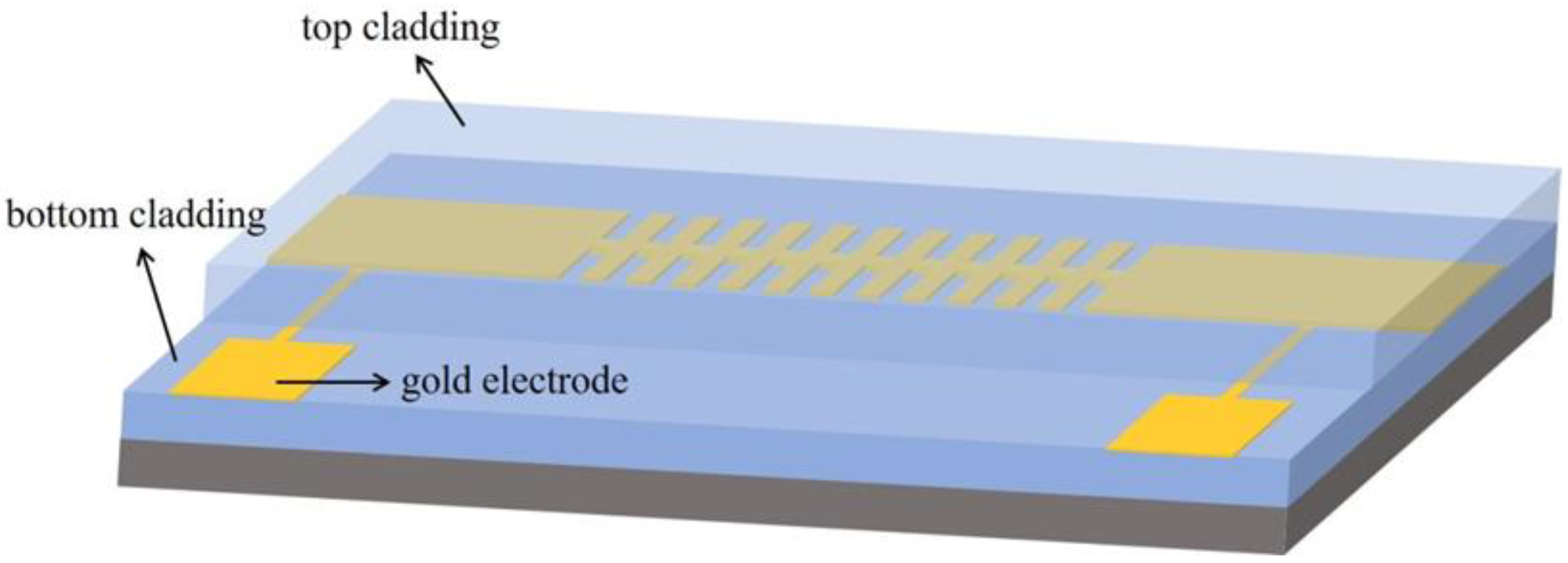
2.2. LRSPP Waveguide Grating
3. Simulations
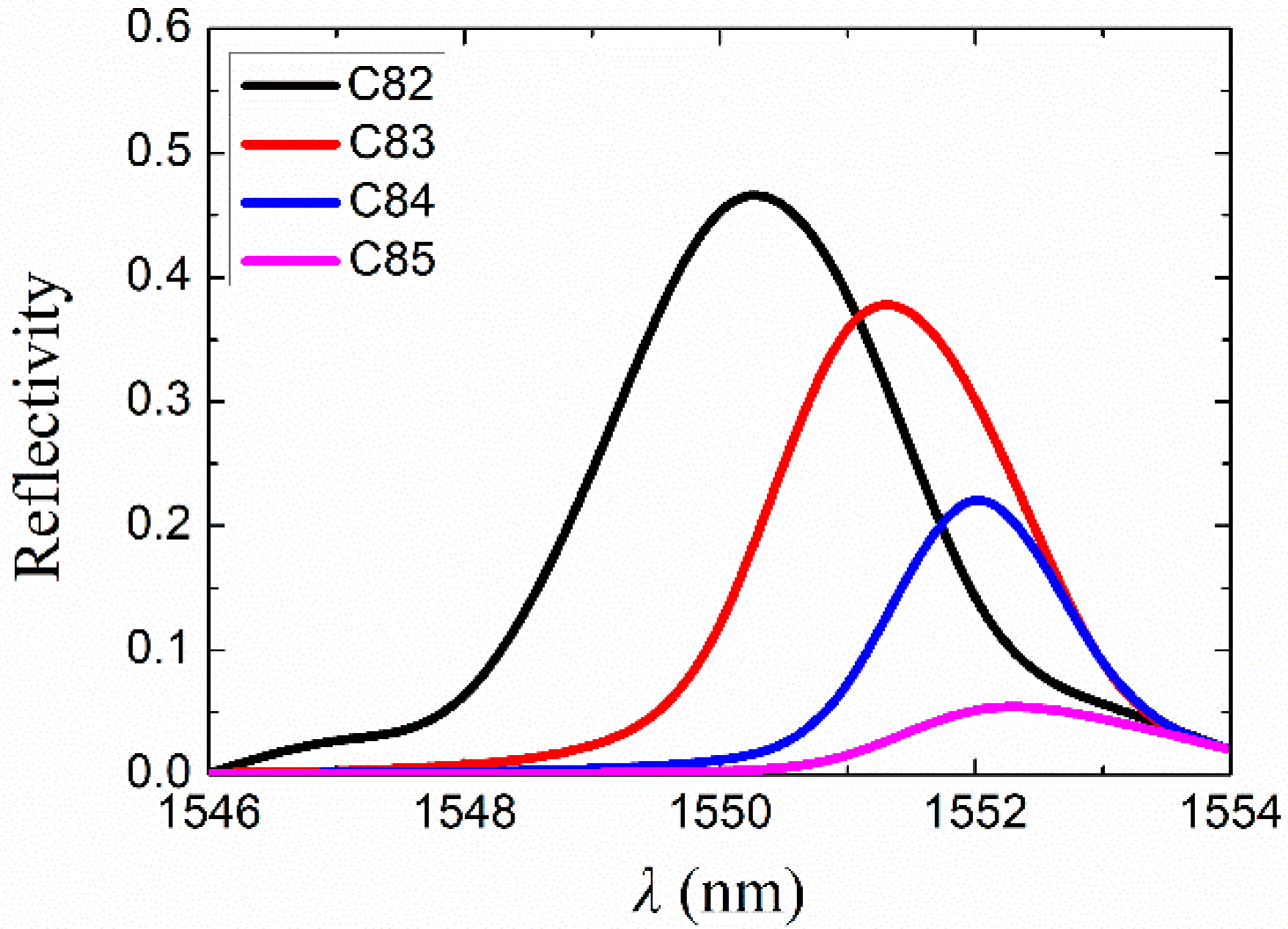
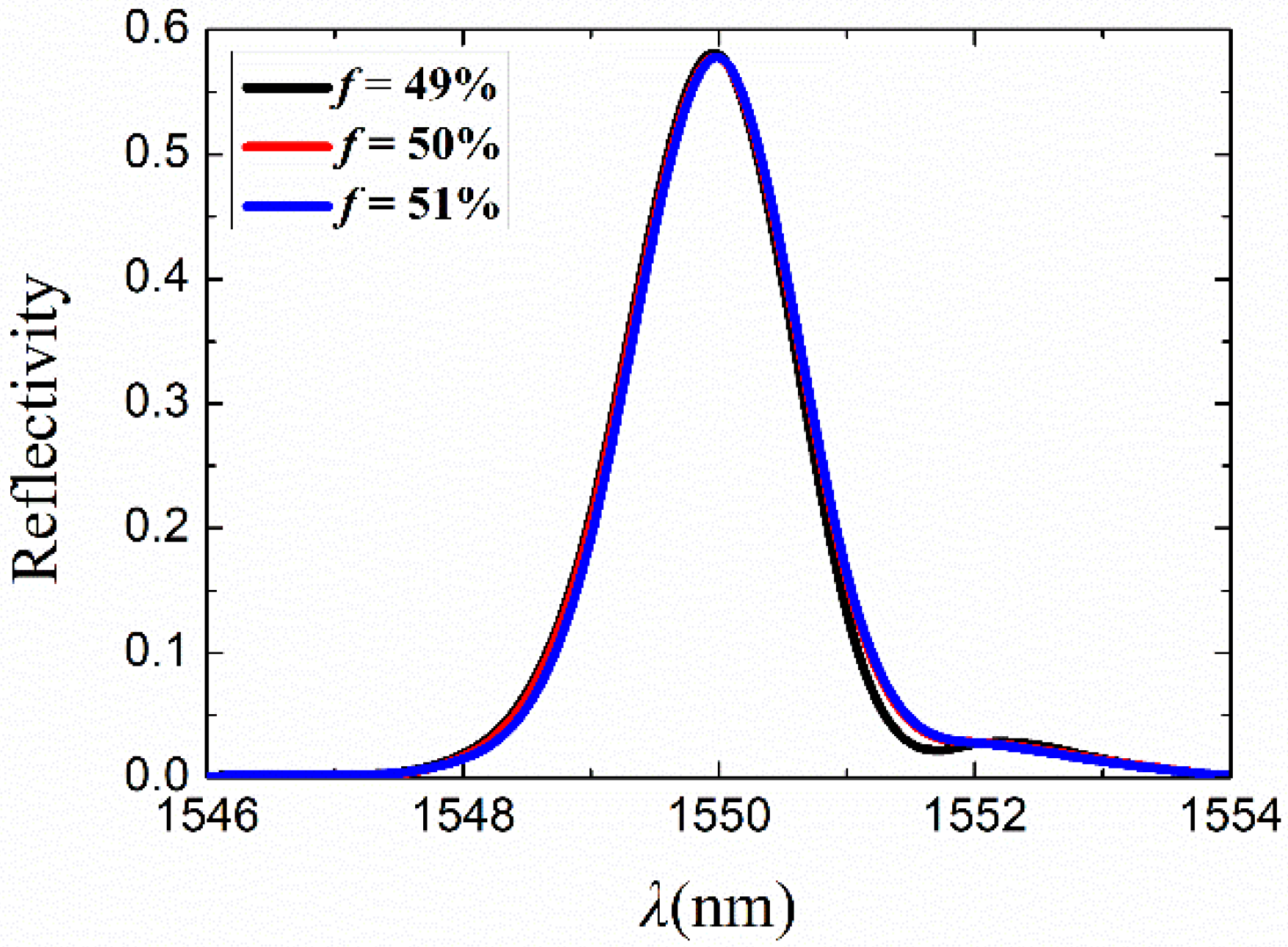
3.1. Grating Width, Height, and Period
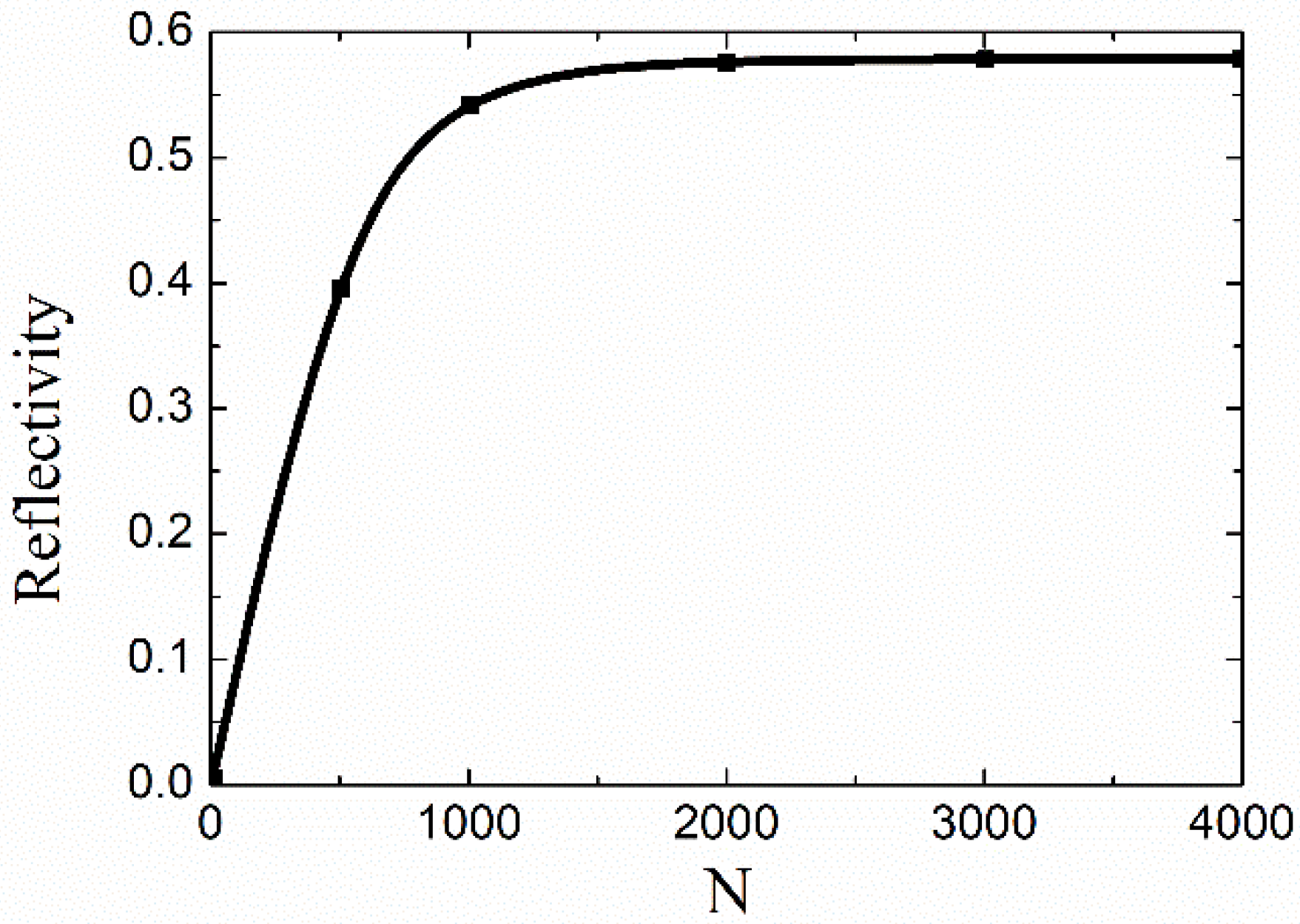
3.2. Grating Length
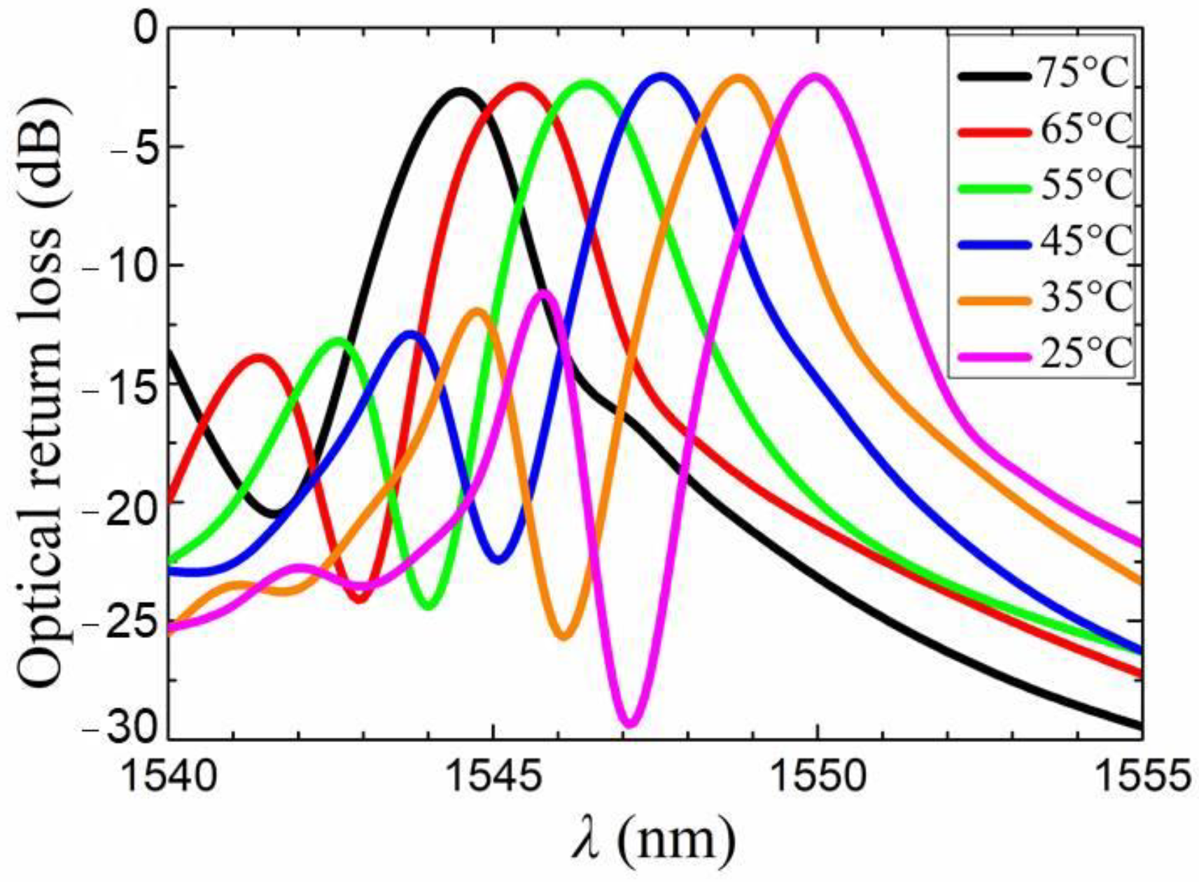
4. Thermal Analysis
- (1)
- for the top and lateral surfaces (n = refractive index),
- (2)
- T = T0 for the bottom boundary,
- (3)
- T = Tm for the heater.
5. Results and Discussion
6. Conclusions
Author Contributions
Funding
Data Availability Statement
Conflicts of Interest
References
- Kobayashi, N.; Sato, K.; Namiwaka, M.; Yamamoto, K.; Watanabe, S.; Kita, T.; Yamada, H.; Yamazaki, H. Silicon photonic hybrid ring-filter external cavity wavelength tunable lasers. J. Lightwave Technol. 2015, 33, 1241–1246. [Google Scholar] [CrossRef]
- Xu, Y.; Liu, S.; Liu, T.; Gao, Y.; Yin, Y.; Sun, X.; Zhang, D. Optical switch based on Ge2Sb2Se4Te1-assisted racetrack microring. Photonics 2022, 9, 117. [Google Scholar] [CrossRef]
- Chen, W.; Xu, Y.; Gao, Y.; Ji, L.; Wang, X.; Sun, X.; Zhang, D. A broadband polarization-insensitive graphene modulator based on dual built-in orthogonal slots plasmonic waveguide. Appl. Sci. 2021, 11, 1897. [Google Scholar] [CrossRef]
- Wang, Y.; Wang, Z.; Yu, Q.; Xie, X.; Posavitz, T.; Mitos, M.J.; Ramaswamy, A.; Norberg, E.J.; Fish, G.A.; Beling, A. High-power photodiodes with 65 GHz bandwidth heterogeneously integrated onto silicon-on-Insulator nano-waveguides. IEEE J. Sel. Top. Quantum Electron. 2018, 24, 1–6. [Google Scholar] [CrossRef]
- Okayama, H.; Onawa, Y.; Takahashi, H.; Shimura, D.; Yaegashi, H.; Sasaki, H. Polarization insensitive silicon waveguide wavelength filter using polarization rotator and mode conversion Bragg grating with resonator cavity. Jpn. J. Appl. Phys. 2020, 59, 128002. [Google Scholar] [CrossRef]
- Zhang, Z.; Novo, A.M.; Liu, D.; Keil, N.; Grote, N. Compact and tunable silicon nitride Bragg grating filters in polymer. Opt. Commun. 2014, 321, 23–27. [Google Scholar] [CrossRef]
- Zhang, Z.; Liu, D.; Felipe, D.D.; Liu, A.; Keil, N.; Grote, N. Polymer embedded silicon nitride thermally tunable Bragg grating filters. Appl. Phys. Lett. 2013, 102, 181105. [Google Scholar] [CrossRef]
- Jin, L.; Lauro, L.D.; Pasquazi, A.; Peccianti, M.; Moss, D.J.; Morandotti, R.; Little, B.E.; Chu, S.T. Optical multi-stability in a nonlinear high-order microring resonator filter. APL Photon. 2020, 5, 056106. [Google Scholar] [CrossRef]
- Laere, F.V.; Roelkens, G.; Ayre, M.; Schrauwen, J.; Baets, R. Compact and highly efficient grating couplers between optical fiber and nanophotonic waveguides. IEEE J. Light. Technol. 2007, 25, 151–156. [Google Scholar] [CrossRef] [Green Version]
- Liu, A.; Felipe, D.D.; Zawadzki, C.; Keil, N.; Grote, N. Birefringence and reflectivity of all-polymer tunable Bragg grating filters with microheaters. IEEE Phocechnol. Lett. 2018, 30, 1325–1328. [Google Scholar] [CrossRef]
- Liu, A.; Zhang, Z.; Felipe, D.D.; Keil, N.; Grote, N. Power-efficient thermo-optic tunable filters based on polymeric waveguide Bragg gratings. IEEE Photon. Technol. Lett. 2014, 26, 313–315. [Google Scholar] [CrossRef]
- Zheng, Z.; Luo, Y.; Yang, H.; Yi, Z.; Zhang, J.; Song, Q.; Yang, W.; Liu, C.; Wu, X.; Wu, P. Thermal tuning of terahertz metamaterial properties based on phase change material vanadium dioxide. Phys. Chem. Chem. Phys. 2022, 24, 8846–8853. [Google Scholar] [CrossRef] [PubMed]
- Chen, H.; Chen, Z.; Yang, H.; Wen, L.; Yi, Z.; Zhou, Z.; Dai, B.; Zhang, J.; Wu, X.; Wu, P. Multi-mode surface plasmon resonance absorber based on dart-type single-layer graphene. RSC Adv. 2022, 12, 7821–7829. [Google Scholar] [CrossRef] [PubMed]
- Zhao, F.; Lin, J.; Lei, Z.; Yi, Z.; Qin, F.; Zhang, J.; Liu, L.; Wu, X.; Yang, W.; Wu, P. Realization of 18.97% theoretical efficiency of 0.9 µm thick c-Si/ZnO heterojunction ultrathin-film solar cells via surface plasmon resonance enhancement. Phys. Chem. Chem. Phys. 2022, 24, 4871–4880. [Google Scholar] [CrossRef] [PubMed]
- Zheng, Z.; Zheng, Y.; Luo, Y.; Yi, Z.; Zhang, J.; Liu, Z.; Yang, W.; Yu, Y.; Wu, X.; Wu, P. Switchable terahertz device combining ultra-wideband absorption and ultra-wideband complete reflection. Phys. Chem. Chem. Phys. 2022, 24, 2527–2533. [Google Scholar] [CrossRef]
- Wu, X.; Zheng, Y.; Luo, Y.; Zhang, J.; Yi, Z.; Wu, X.; Cheng, S.; Yang, W.; Yu, Y.; Wu, P. A four-band and polarization-independent BDS-based tunable absorber with high refractive index sensitivity. Phys. Chem. Chem. Phys. 2021, 23, 26864–26873. [Google Scholar] [CrossRef]
- Zhou, F.; Qin, F.; Yi, Z.; Yao, W.T.; Liu, Z.; Wu, X.; Wu, P. Ultra-wideband and wide-angle perfect solar energy absorber based on Ti nanorings surface plasmon resonance. Phys. Chem. Chem. Phys. 2021, 23, 17041–17048. [Google Scholar] [CrossRef]
- Ji, L.; Sun, X.; He, G.; Liu, Y.; Wang, X.; Yi, Y.; Chen, C.; Wang, F.; Zhang, D. Surface plasmon resonance refractive Index sensor based on ultraviolet bleached polymer waveguide. Sens. Actuator B-Chem. 2017, 244, 373–379. [Google Scholar] [CrossRef]
- Ji, L.; Yang, S.; Shi, R.; Fu, Y.; Su, J.; Wu, C. Polymer waveguide coupled surface plasmon refractive index sensor: A theoretical study. Photonic Sens. 2020, 10, 353–363. [Google Scholar] [CrossRef]
- Lertvachirapaiboon, C.; Baba, A.; Ekgasit, S.; Shinbo, K.; Kato, K.; Kaneko, F. Transmission surface plasmon resonance imaging of silver nanoprisms enhanced propagating surface plasmon resonance on a metallic grating structure. Sens. Actuator B-Chem. 2017, 249, 39–43. [Google Scholar] [CrossRef]
- Leon, I.D.; Berini, P. Spontaneous emission in long-range surface plasmon-polariton amplifiers. Phys. Rev. B. 2011, 83, 081414. [Google Scholar] [CrossRef]
- Marell, M.J.H.; Smalbrugge, B.; Geluk, E.J. Plasmonic distributed feedback lasers at telecommunications wavelengths. Opt. Express. 2011, 19, 15109–15118. [Google Scholar] [CrossRef] [PubMed] [Green Version]
- Ding, K.; Liu, Z.; Yin, L. Electrical injection, continuous wave operation of subwavelength-metallic-cavity lasers at 260 K. Appl. Phys. Lett. 2011, 98, 231108. [Google Scholar] [CrossRef] [Green Version]
- Xu, Y.; Wang, F.; Gao, Y.; Zhang, D.; Sun, X.; Berini, P. Straight long-range surface plasmon polariton waveguide sensor operating at λ0 = 850 nm. Sensors 2020, 20, 2507. [Google Scholar] [CrossRef] [PubMed]
- Lee, J.; Lu, F.; Belkin, M.A. Widely-tunable optical bandpass filter based on long-range surface plasmon polaritons. Proc. SPIE. 2012, 8457, 84572G. [Google Scholar]
- Charbonneau, S.J.; Berini, P. Theoretical performance of Bragg gratings based on long-range surface plasmon-polariton waveguides. J. Opt. Soc. Am. A Opt. Image Sci. Vis. 2006, 23, 1757–1767. [Google Scholar] [CrossRef] [PubMed]
- Dorian, O.; Diego, P.G.; Carlos, A.R. Subwavelength engineering and asymmetry: Two efficient tools for sub-nanometer-bandwidth silicon Bragg filters. Opt. Lett. 2018, 43, 3208–3211. [Google Scholar]
- Diemeer, M. Polymeric thermo-optic space switches for optical communications. Opt. Mater. 1998, 9, 192–200. [Google Scholar] [CrossRef]
- Huang, S.T.; Lai, C.C.; Sheu, F.W.; Tsai, W.S. Characterization of long-range plasmonic waveguides at visible to near-infrared regime. AIP Adv. 2017, 7, 125221. [Google Scholar] [CrossRef]
- Vernoux, C.; Chen, Y.T.; Markey, L.; Sparchez, C.; Aarocas, J.; Felder, T.; Neitz, M.; Brusberg, L.; Weeber, J.C.; Bozhevolnyi, S.I.; et al. Flexible long-range surface plasmon polariton single-mode waveguide for optical interconnects. Opt. Mater. Express 2018, 8, 469–484. [Google Scholar] [CrossRef]
- Ji, L.; He, G.; Gao, Y.; Sun, X.; Yi, Y.; Wang, X.; Chen, C.; Wang, F.; Zhang, D. SU-8 grating assisted intermodal interference in surface plasmon polariton waveguide. Opt. Mater. Express 2017, 7, 2560–2570. [Google Scholar] [CrossRef]
- Liu, A.; Zhang, Z.; Liu, D.; Keil, N.; Grote, N. Thermo-optic simulations of silicon nitride/polymer hybrid waveguides. Integr. Opt. Phys. Simul. Int. Soc. Opt. Photonics 2013, 8781, 878105. [Google Scholar]
- Gazzaz, K.; Berini, P. Theoretical biosensing performance of surface plasmon polariton Bragg gratings. Appl. Opt. 2015, 54, 1673–1680. [Google Scholar] [CrossRef]
- Ji, L.; Liu, T.; He, G.; Sun, X.; Wang, X.; Yi, Y.; Chen, C.; Wang, F.; Zhang, D. UV-written long-period grating based on long-range surface plasmon-polariton waveguide. IEEE Photon. Technol. Lett. 2016, 28, 633–636. [Google Scholar] [CrossRef]
- Feng, H.; Liu, Z.; Zhang, J.; Ran, L.; Gao, Y. An ultra-high efficient plasmon waveguide filter with enhanced filtering effect. Opt. Commun. 2021, 499, 127287. [Google Scholar] [CrossRef]


| Material | Density (kg/m3) | Heat Capacity (J/kg/K) | Thermal Conductivity (W/m/K) |
|---|---|---|---|
| Au | 19320 | 128 | 317 |
| SU-8 | 1190 | 1420 | 0.2 |
| Si | 2340 | 700 | 163 |
| Platform | Structure | Working Bandwidth | f3-dB | Ref |
|---|---|---|---|---|
| Polymer/SiNx | Bragg grating | 1500−1570 nm | ~6.3 nm | [6] |
| Silicon | Bragg grating | ~1526 nm | 0.8 nm (symmetric) 0.6 nm (asymmetric) | [27] |
| MIM LRSPP | Cavity | 500−1250 nm | >4 nm | [35] |
| This work (IMI LRSPP) | Bragg grating | 1540−1555 nm | ~1.1 nm |
Publisher’s Note: MDPI stays neutral with regard to jurisdictional claims in published maps and institutional affiliations. |
© 2022 by the authors. Licensee MDPI, Basel, Switzerland. This article is an open access article distributed under the terms and conditions of the Creative Commons Attribution (CC BY) license (https://creativecommons.org/licenses/by/4.0/).
Share and Cite
Xu, Y.; Yue, J.; Wang, M.; Sun, X.; Zhang, D. Tunable Narrow-Band Filter Based on Long-Range Surface Plasmon Polariton Waveguide Bragg Grating. Photonics 2022, 9, 344. https://doi.org/10.3390/photonics9050344
Xu Y, Yue J, Wang M, Sun X, Zhang D. Tunable Narrow-Band Filter Based on Long-Range Surface Plasmon Polariton Waveguide Bragg Grating. Photonics. 2022; 9(5):344. https://doi.org/10.3390/photonics9050344
Chicago/Turabian StyleXu, Yan, Jianbo Yue, Manzhuo Wang, Xiaoqiang Sun, and Daming Zhang. 2022. "Tunable Narrow-Band Filter Based on Long-Range Surface Plasmon Polariton Waveguide Bragg Grating" Photonics 9, no. 5: 344. https://doi.org/10.3390/photonics9050344
APA StyleXu, Y., Yue, J., Wang, M., Sun, X., & Zhang, D. (2022). Tunable Narrow-Band Filter Based on Long-Range Surface Plasmon Polariton Waveguide Bragg Grating. Photonics, 9(5), 344. https://doi.org/10.3390/photonics9050344