Abstract
We showed that the nonlinear Mach–Zehnder interferometer may be used not only for enhancing temporal contrast, as proposed earlier, but also for increasing pulse power due to efficient pulse compression. The interferometer introduces into the output pulse a nonlinear phase equal to π/2. This allows increasing laser power by a factor of 1.5 only by means of a chirped mirror. Use of an additional nonlinear plate leads to a multi-fold power increase retaining the contrast enhancement.
1. Introduction
High temporal contrast has an important role in experiments on studying the behavior of matter in extreme light fields. Temporal contrast is the ratio of the intensity at the peak of the pulse to the intensity on its pedestal. The pedestal appears, as a rule, due to amplified spontaneous emission in laser amplifiers of CPA lasers (chirped pulse amplification) [1], or due to amplified parametric emission in OPCPA lasers (optical parametric chirped pulse amplification) [2]. The most popular techniques for contrast enhancement are plasma mirrors [3], harmonic generation [4], and cross-polarized wave (XPW) generation [5]. XPW is based on cubic nonlinearity. Recently, several new ideas have been proposed for contrast enhancement, by means of a nonlinear phase induced by cubic nonlinearity: spectral filtering [6,7], spatial filtering [8], a nonlinear polarization interferometer [9], as well as a nonlinear Mach–Zehnder interferometer with symmetric arms [10]. In the latter case, the phase difference without non-linearity equals π, and the radiation of the pedestal does not pass to the dark port (see Figure 1a). On the contrary, the main pulse acquires a nonlinear phase B (B-integral) in one channel, and a zero nonlinear phase in another one. If B is nonzero, then the dark port does not become completely dark. If ∆B = π, then the dark port becomes a light port, and the major part of the main pulse comes through this port. As a result, the contrast will be infinitely high if = π. In practice, the contrast enhancement is determined by the inaccuracy of meeting the condition π.
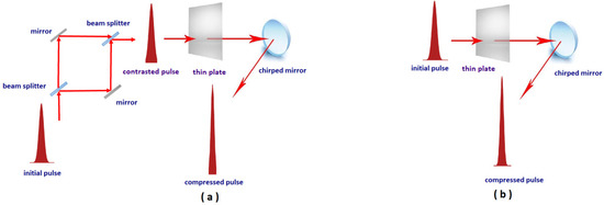
Figure 1.
Optical schemes with nonlinear Mach–Zehnder interferometer (a) and without interferometer (b).
Due to self-phase modulation (SPM) in a nonlinear medium, and subsequent reflection from the chirped mirror (CM), the pulse may be compressed, and hence the peak power increases. The method is called TFC (thin film compression) [11], CafCA (compression after compressor approach) [12], or post-compression [13]. For pulses with energy of tens of Joules [14,15,16], the multiple compression of femtosecond laser pulses was demonstrated with almost no energy loss; for more details, see the review [17].
In this paper, we show that a nonlinear Mach–Zehnder interferometer may be used not only for contrast enhancement, but also for multi-fold pulse compression simultaneously.
2. Nonlinear Mach–Zehnder Interferometer for Enhancement of Contrast and Pulse Compression
For the Mach–Zehnder interferometer (see Figure 1a), the expressions for intensities I1 and I2 at the outputs of the arms (ports) have the form [10]
Here, I0 is the intensity at the interferometer input (I0 = I1 + I2); is the linear phase difference acquired by the pulses during propagation along the interferometer arms; B(t) = (2π/λ)Io(t)n2L is the nonlinear phase (B-integral) accumulated in both beam splitters; L is length of the beam path in the beam splitters; λ is the wavelength; n2 is the nonlinear refractive index; and R is the reflectivity of the beam splitters.
Under the conditions = π and R = 0.5, the value of I1 in Equation (1) may be exactly zero in the absence of a nonlinear phase (B = 0). On the other hand, at high intensity, the nonlinear phase is accumulated, and the intensity I1 takes on a maximal value, provided that B = π, = π and R = 0.5. As a result, the pulse emerging at this port has a higher contrast. Moreover, the pulse duration shortened after reflection from the CM. For example, an input pulse of 50 fs may be shortened to 38 fs [10], which is a tiny compression factor.
The first way to increase the compression factor is to use a CM to remove the chirp from the pulse. It is easy to show that the output pulse I1 accumulates a nonlinear phase Bout = π/2 because output pulse accumulates nonlinear phase Bout = (B1 + B2)/2. Where, B1 and B2 is nonlinear phases in the interferometer arms 1 and 2, respectively. Since B1 = π and B2 = 0, therefore Bout = π/2. As shown below, this acquired nonlinear phase leads to compression to about 25 fs, which is still a modest value, because of a small value of Bout. The second way is to introduce an additional nonlinear phase Badd by adding an additional nonlinear plate before the CM (see Figure 1a). Thus, the total value of the B-integral is BΣ = π/2 + Badd. We will study the efficiency of pulse compression in this case. As a reference, we will use compression without interferometer (without contrast enhancement) with the B-integral equal to BΣ (Figure 1b). The reference case is obviously more robust and practical, but it does not provide any impact on the pedestal.
3. Numerical Model
Pulse propagation in a nonlinear plate is described by the nonlinear Schrödinger Equation (3) [18]
where A is the normalized amplitude of the E-field, is the normalized time, and the coefficients α, β and γ are defined as
where is the central frequency of the pulse.
We used Equation (3) for the numerical modeling of pulse propagation, both in the interferometer’s beam splitters, and in thin plates. Equation (3) is solved numerically by the split step Fourier method (SSFM). This method is widely used for solving the problem of pulse propagation in a nonlinear dispersive medium. The main advantage of this method is the use of the fast Fourier transform (FFT) algorithm, which makes it faster than the finite difference methods. Therefore, we have developed a MATLAB algorithm to implement the numerical FFT algorithm. To demonstrate the compression of the pulse as a function of BΣ, we scanned the thickness of the nonlinear media, keeping the other parameters constant: input intensity 1 TW/cm2, input pulse duration (FWHM) 50 fs and 30 fs, and wavelength 910 nm. We chose material parameters of fused silica as the most popular material: nonlinear refractive index n2 = 2.75 × 10⁻¹⁶ cm2/W and group velocity dispersion α = 280 fs2/cm.
SPM leads to spectral broadening; the pulse becomes positively chirped. Thus, the pulse may be compressed by reflection on the CM with negative dispersion (Figure 1). We restrict the consideration to the case in which the CM introduced a purely quadratic spectral phase, i.e., group velocity dispersion only. Such a type of CMs cannot compress the pulse to a Fourier transform limit, but they are usually commercially available. In this case, the CM is embedded in the model using Equation (4)
where Acompressed is the amplitude after compression (after reflection from the CM) and Achirped is the amplitude of the field incident on the CM, F and F−1 are the direct and inverse Fourier transforms, respectively. The parameter α is the group velocity dispersion parameter of the CM.
4. Results and Discussion
The primary effect of SPM is spectral broadening. So, first of all, we compare the spectral bandwidth before the CM. Then, we should choose the CM dispersion αopt. It may be chosen to minimize the compressed pulse duration or to maximize peak power. However, we prefer the last case, because increasing the pulse power is a primary goal for most applications. Furthermore, we study pulse shortening and power enhancement.
4.1. Spectral Broadening
The results of calculations are shown in Figure 2. The pulse in the scheme with interferometer has a wider spectral bandwidth than that without interferometer, even though BΣ is the same. This phenomenon is explained as follows. At the interferometer output (Figure 1a), the beam is a sum of two beams: one with B = 0 and the other with B = π. The spectrum of the first beam is not broadened at all, while the spectrum of the second one is broadened much stronger than the spectrum of the single beam with BΣ = π/2 in the reference case (Figure 1b). In other words, due to the nonlinear nature of SPM, the spectral broadening with interferometer is higher than in the case without the interferometer, even if BΣ = π/2 in both cases (see Figure 2a,c). An additional nonlinear plate increases BΣ up to 5, but keeps this difference (Figure 2b,d).
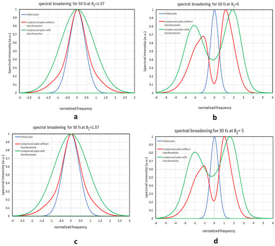
Figure 2.
Spectrum of the initial pulse, compressed pulse in the scheme with interferometer (Figure 1a), and compressed pulse in the scheme without interferometer (Figure 1b) for 50 fs (a,b) and 30 fs (c,d) input pulses at BΣ = π/2 (a,c) and BΣ = 5 (b,d). Horizontal axes are normalized to the input pulse bandwidth.
The spectra for 50 fs and 30 fs input pulses are very similar (note that the horizontal axes are normalized to the input pulse bandwidths 8.82 × 10¹² Hz and 1.47 × 10¹³ Hz for 50 fs and 30 fs, respectively). The small difference between 50 fs and 30 fs at BΣ = 5 is due to the fact that the bandwidth for 30 fs input pulse becomes comparable to the optical frequency.
4.2. Optimal Chirped Mirror Dispersion αopt
As mentioned above, we defined the optimal CM dispersion αopt as a dispersion which maximizes compressed pulse peak power. When CM dispersion is not exactly equal to αopt, the compressed pulse power is smaller. We calculated αopt as a function of BΣ. The results are shown in Figure 3, from which it is seen that correcting the quadratic spectral phase component for higher values of the B-integral necessitates a lower (in modulus) chirped mirror dispersion αopt. Moreover, it is clear from Figure 3 that αopt is smaller in the case with interferometer than without it. The smaller value of αopt provides a practical advantage, because the fabrication of CM with a higher dispersion is a more serious challenge. It is worth noticing that, at a high value of B-integral, αopt is almost independent of BΣ. Hence, the same CM may be used for a B-integral in a wide range of values, eliminating the impact of instability of the laser parameters.
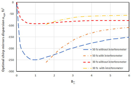
Figure 3.
BΣ-dependence of parameter αopt for different pulse durations with and without interferometer.
4.3. Pulse Compression
The results are shown in Figure 4. The compressed pulse in the scheme with interferometer is even shorter than in the scheme without interferometer. It is explained by the wider spectrum (see Figure 2). For instance, at BΣ = 5, for 50 fs input pulse, the compressed pulse duration decreased to about 14 fs in the scheme without interferometer, and to about 12 fs with interferometer; for the 30 fs input pulse, the compressed pulse duration decreased to about 9 fs in the case without interferometer, and to about 7 fs in the scheme with interferometer.
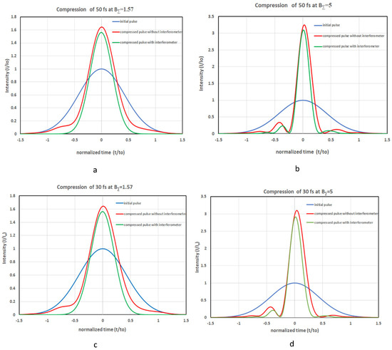
In addition, the intensity in the compressed pulse wings is lower in the case with interferometer because the interferometer remains closed for the input pulse tails, and the chirp in the tails differs greatly from the linear chirp. So, removing the tails from the input pulse causes the compressed pulse to be closer to the Fourier transform limited one (cf. the green and red curves in Figure 4). Thus, from the pulse compression viewpoint, the case with interferometer (Figure 1a) is more preferable than the reference case (Figure 1b).
4.4. Peak Power Increase
From the viewpoint of peak power, the case with interferometer (Figure 1a) strongly differs from the reference case (Figure 1b). The latter is energy lossless, while the first one is not. Energy is lost because the dark port of the interferometer becomes perfectly light only at B = π, i.e., only at t = 0, i.e., for the central part of the pulse. For t ≠ 0, the interferometer transmission is below 100% by virtue of B ≠ π. For the pulse periphery, B << π and the pulse do not pass through the interferometer at all. The energy transmission of the interferometer for a Gaussian pulse with B (t = 0) = π is 76% for any pulse duration. This inevitable disadvantage reduces the power of compressed pulses. Nevertheless, as seen from Figure 4, the peak power is almost the same for both cases. Figure 5 shows that this is true for any value of B-integral. In spite of 24% energy loss in the interferometer, the superiority of the case without interferometer is below 10%. This is explained by more efficient pulse compression in the case with the interferometer.
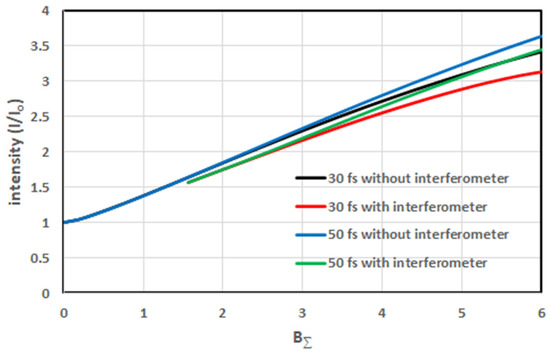
Figure 5.
Output pulse intensity as a function of B- integral.
5. Conclusions
Numerical modeling confirmed that the nonlinear Mach–Zehnder interferometer may be used not only to enhance the temporal contrast, but also to increase the pulse power due to efficient pulse compression. The pulse shortens due to self-phase modulation and a chirped mirror. Self-phase modulation occurs during propagation, both in the interferometer beam splitters, and in an additional nonlinear plate. We showed that pulse compression in the scheme with interferometer is either the same or even better than the standard compression in the scheme without interferometer and without contrast improvement.
Author Contributions
Conceptualization, E.K.; methodology, Y.N.; software, Y.N.; validation, E.K. and Y.N.; formal analysis E.K.; investigation, Y.N.; resources, Y.N.; data curation, Y.N.; writing—original draft preparation, E.K. and Y.N.; writing—review and editing, E.K. and Y.N.; visualization, E.K.; supervision E.K.; project administration, E.K.; funding acquisition, E.K.; All authors have read and agreed to the published version of the manuscript.
Funding
This research was supported by the Center of Excellence “Center of Photonics” funded by the Ministry of Science and Higher Education of the Russian Federation, agreement No. 075-15-2020-906.
Institutional Review Board Statement
Not applicable.
Informed Consent Statement
Not applicable.
Data Availability Statement
Not applicable.
Acknowledgments
This work was supported by the Center of Excellence “Center of Photonics” funded by the Ministry of Science and Higher Education of the Russian Federation, agreement No. 075-15-2020-906.
Conflicts of Interest
The authors declare no conflict of interest.
References
- Strickland, D.; Mourou, G. Compression of amplified chirped optical pulses. Opt. Commun. 1985, 56, 219–221. [Google Scholar] [CrossRef]
- Dubietis, A.; Jonusauskas, G.; Piskarskas, A. Powerful femtosecond pulse generation by chirped and stretched pulse parametric amplification in BBO crystal. Opt. Commun. 1992, 88, 437–440. [Google Scholar] [CrossRef]
- Lévy, A.; Ceccotti, T.; D’Oliveira, P.; Réau, F.; Perdrix, M.; Quéré, F.; Monot, P.; Bougeard, M.; Lagadec, H.; Martin, P.; et al. Double plasma mirror for ultrahigh temporal contrast ultraintense laser pulses. Opt. Lett. 2007, 32, 310–312. [Google Scholar] [CrossRef] [PubMed]
- Mironov, S.Y.; Lozhkarev, V.V.; Ginzburg, V.N.; Khazanov, E.A. High-efficiency second-harmonic generation of superintense ultrashort laser pulses. Appl. Opt. 2009, 48, 2051–2057. [Google Scholar] [CrossRef] [PubMed]
- Jullien, A.; Albert, O.; Burgy, F.; Hamoniaux, G.; Rousseau, J.-P.; Chambaret, J.-P.; Augé-Rochereau, F.; Chériaux, G.; Etchepare, J.; Minkovski, N.; et al. 10^-10 temporal contrast for femtosecond ultraintense lasers by cross-polarized wave generation. Opt. Lett. 2005, 30, 920–922. [Google Scholar] [CrossRef] [PubMed] [Green Version]
- Buldt, J.; Müller, M.; Klas, R.; Eidam, T.; Limpert, J.; Tünnermann, A. Temporal contrast enhancement of energetic laser pulses by filtered self-phase-modulation-broadened spectra. Opt. Lett. 2017, 42, 3761–3764. [Google Scholar] [CrossRef] [PubMed]
- Mironov, S.Y.; Starodubtsev, M.V.; Khazanov, E.A. Temporal contrast enhancement and compression of output pulses of ultra-high power lasers. Opt. Lett. 2021, 46, 1620–1623. [Google Scholar] [CrossRef] [PubMed]
- Khazanov, E.A. Enhancing the time contrast and power of femtosecond laser pulses by an optical wedge with cubic nonlinearity. Quantum Electron. 2021, 51, 433–436. [Google Scholar] [CrossRef]
- Khazanov, E. Nonlinear polarization interferometer for enhancement of laser pulse contrast and power. Opt. Express 2021, 29, 17277–17285. [Google Scholar] [CrossRef] [PubMed]
- Khazanov, E.A.; Mironov, S.Y. Nonlinear interferometer for increasing the contrast ratio of intense laser pulses. Quantum Electron. 2019, 49, 337–343. [Google Scholar] [CrossRef]
- Mourou, G.; Mironov, S.; Khazanov, E.; Sergeev, A. Single cycle thin film compressor opening the door to Zeptosecond-Exawatt physics. Eur. Phys. J. Spec. Top. 2014, 223, 1181–1188. [Google Scholar] [CrossRef]
- Ginzburg, V.N.; Yakovlev, I.V.; Zuev, A.S.; Korobeinikova, A.A.; Kochetkov, A.A.; Kuz’min, A.A.; Mironov, S.Y.; Shaykin, A.A.; Shaykin, I.A.; Khazanov, A.E. Compression after compressor: Threefold shortening of 200-TW laser pulses. Quantum Electron. 2019, 49, 299–301. [Google Scholar] [CrossRef]
- Balla, P.; Bin Wahid, A.; Sytcevich, I.; Guo, C.; Viotti, A.-L.; Silletti, L.; Cartella, A.; Alisauskas, S.; Tavakol, H.; Grosse-Wortmann, U.; et al. Postcompression of picosecond pulses into the few-cycle regime. Opt. Lett. 2020, 45, 2572–2575. [Google Scholar] [CrossRef] [PubMed]
- Ginzburg, V.; Yakovlev, I.; Zuev, A.; Korobeynikova, A.; Kochetkov, A.; Kuzmin, A.; Mironov, S.; Shaykin, A.; Shaikin, I.; Khazanov, E.; et al. Fivefold compression of 250-TW laser pulses. Phys. Rev. A 2020, 101, 013829. [Google Scholar] [CrossRef]
- Ginzburg, V.N.; Yakovlev, I.V.; Zuev, A.S.; Korobeynikova, A.P.; Kochetkov, A.A.; Kuzmin, A.A.; Mironov, S.Y.; Shaykin, A.A.; Shaikin, I.A.; Khazanov, E.A. Two-stage nonlinear compression of high-power femtosecond laser pulses. Quantum Electron. 2020, 50, 331–334. [Google Scholar] [CrossRef]
- Ginzburg, V.; Yakovlev, I.; Kochetkov, A.; Kuzmin, A.; Mironov, S.; Shaikin, I.; Shaykin, A.; Khazanov, E. 11 fs, 1.5 PW laser with nonlinear pulse compression. Opt. Express 2021, 29, 28297–28306. [Google Scholar] [CrossRef] [PubMed]
- Khazanov, E.A.; Mironov, S.Y.; Mourou, G. Nonlinear compression of high-power laser pulses: Compression after compressor approach. Phys.-Uspekhi 2019, 62, 1096–1124. [Google Scholar] [CrossRef]
- Anderson, D.P.; Lisak, M. Nonlinear asymmetric self-phase modulation and self-steepening of pulses in long optical waveguides. Phys. Rev. A 1983, 27, 1393–1398. [Google Scholar] [CrossRef]
Publisher’s Note: MDPI stays neutral with regard to jurisdictional claims in published maps and institutional affiliations. |
© 2021 by the authors. Licensee MDPI, Basel, Switzerland. This article is an open access article distributed under the terms and conditions of the Creative Commons Attribution (CC BY) license (https://creativecommons.org/licenses/by/4.0/).