


Abstract
Multichannel vortex beams serve as an essential physical source for enabling multi-spot laser processing and high-dimensional spatial multiplexing communications. We demonstrate a compact, flexibly tunable multichannel vortex beam generator using spatially structured bidirectional two-color pump vortex four-wave mixing in a single 133Cs vapor cell. To enhance spatial multiplexing, both sides of the cell are utilized. By engineering the propagation directions and frequencies of five input beams, we establish a nonlinear interaction region that supports 16 concurrent phase-matching conditions, thereby enabling the parallel generation of up to eight vortex channels. The orbital angular momentum of the output beams follows deterministic algebraic rules, allowing for programmable control via tailored input orbital angular momentum combinations. Moreover, the channel count can be linearly tuned by selectively deactivating pumps—each switched-off pump reduces the number of output channels by two. This flexible control over orbital angular momentum states, together with channel count and spatial arrangement, establishes a highly integrated platform for on-demand vortex generation. This work highlights the potential of spatially bidirectional structured pumping in atomic vapor to expand optical dimensionality and enhance multiplexing capacity, paving the way toward multidimensional communications, quantum networks, and integrated photonics.
1. Introduction
Vortex beams [1,2] are a type of transverse structured light field carrying orbital angular momentum (OAM), offering an additional degree of freedom for applications such as high-dimensional optical communications [3,4], quantum information [5,6,7,8], and rotation-based precision measurement [9] and micro/nano-manipulation [10,11,12]. Given this broad application landscape, the ability to generate high-performance and flexibly controllable multi-vortex beams (that is, beams carrying identical or different OAM states at distinct spatial positions) has become increasingly essential [2] to address growing demands in applications like spatial multiplexing-based parallel information transmission [13], high-resolution far-field microscopy [14], and multi-spot laser processing [15,16].
Currently, the widely used methods for generating multiple vortex beams can be classified into two categories: extracavity diffractive modulation, which relies on devices such as Dammann gratings [17], computer-generated holograms on spatial light modulators [18,19], or metasurfaces [20,21]; and intracavity mode selection, implemented through techniques like fabricating concentric-ring patterns [22] or circular defect spots [23] on cavity mirrors, or by employing spatially structured pumping [24] schemes, including double-ended polarized pumping and off-axis pumping [25].
In parallel, coherent atomic systems have emerged as a versatile platform for generating multichannel vortex beams, owing to their flexible controllability over medium absorption, dispersion, and nonlinear optical response. An additional advantage is that the frequency of the generated multi-vortex beams can be directly matched to atomic resonance lines, providing naturally qualified light sources for quantum communication networks based on atomic ensembles. For instance, within an Electromagnetically Induced Transparency (EIT) configuration, a standing-wave coupling field—formed by the interference between a Gaussian beam and a vortex beam—can modulate atoms into a subwavelength-scale forked photonic lattice. This modulation effectively alters the refractive index, thus transforming the atomic system into a dynamic diffraction grating [26,27]. When a Gaussian probe beam propagates through this grating, it undergoes phase superposition and is diffracted into multiple channels of vortex beams. On the other hand, the nonlinear four-wave mixing (FWM) process in atomic vapor cells exhibits inherent advantages for generating multiple vortex beams because of its intrinsic spatial multimode nature and phase-matching mechanism that relies on closed-loop wavevector geometry. Specifically, under a spatially structured pumping configuration [28,29,30], if the input light is simultaneously modulated into vortex beams, multiple vortex FWM processes with different phase-matching conditions can be excited within a single atomic vapor cell. This enables the generation of spatially separated multi-vortex beams, thereby facilitating the parallel construction of multiple optical modes and the coherent transfer of OAM. The existing schemes based on Λ-type atomic FWM system usually adopt a co-propagating dual-pump configuration [31,32,33]. Although multiple vortex beams can be generated, the resulting light field distribution is typically confined to one side of the cylindrical vapor cell, leaving the spatial multiplexing capability largely underutilized and thus limiting further enhancement of both channel count and system integration. Studies have shown that bidirectional pumping serves as an effective phase-matching approach [34,35,36,37], which supports counter-propagating FWM processes and provides a physical foundation for achieving bidirectional, multichannel light field generation in a single cell. For example, in a recent study on vortex FWM in a double-Λ-type hot atomic system, Xin Li et al. demonstrated that an additional pair of amplified signals in the opposite direction is generated by introducing an additional counter-propagating collinear pump field into the original one-way single-pump configuration. Consequently, the number of amplification channels is successfully extended from one-way dual channels to bidirectional four channels [37]. However, in the context of spatial multiplexing, it remains a challenge to further increase the channel count and incorporate advanced mode control, such as programmable OAM.
In this paper, as a continuation of our group’s previous work on spatially structured co-propagating two-beam pump multi-FWM in a single vapor cell [32], we propose a scheme for generating multichannel vortex beams based on spatially structured bidirectional two-color-pump FWM. Implemented in a single 133Cs vapor cell, our scheme carefully designs the propagation directions, frequencies, and OAM states of multiple input beams (e.g., four pump beams and one probe beam). This creates a nonlinear interaction region capable of simultaneously supporting 16 distinct phase-matching conditions, thereby yielding a total of 8 vortex beam channels propagating in both the forward and backward directions of the cell. Furthermore, these OAM modes can be flexibly controlled through varying the OAM mode combinations of the FWM input beams. This work not only provides a compact, flexibly adjustable physical implementation for generating multichannel vortex light but also demonstrates the significant potential of combining bidirectional spatially structured pumping with atomic media for expanding optical field dimensions and enhancing spatial multiplexing capability. It is expected to provide key components and a technical basis for future atom-based multidimensional optical communications, distributed quantum networks, and integrated photonic systems.
2. Experimental Setup
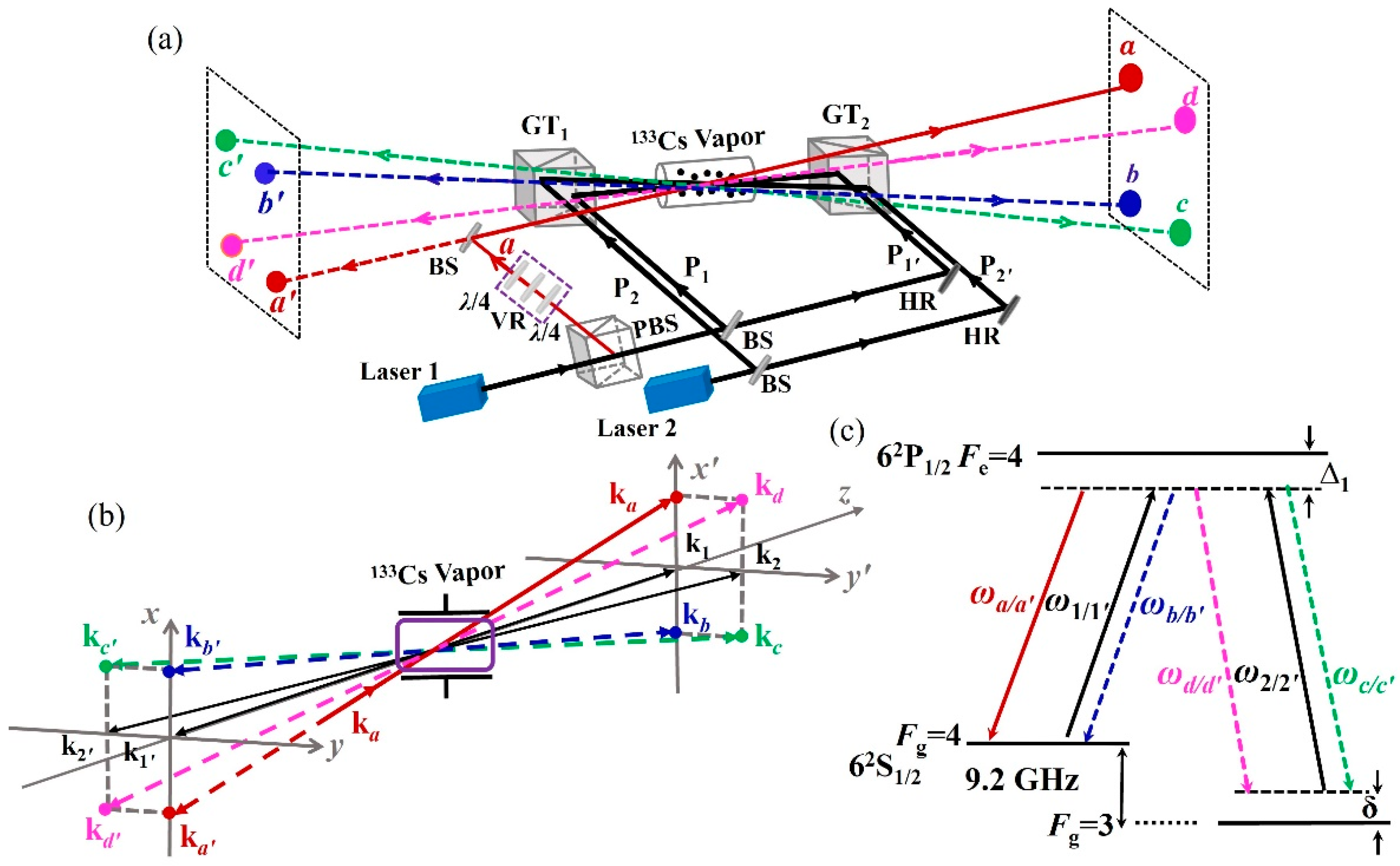
Our spatially structured bidirectional two-color pump FWM experiment is implemented using the optical layout shown in Figure 1a. Two grating-feedback external-cavity diode lasers (Toptica DL-TA, Toptica Photonics AG, Gräfelfing, Bavaria, Germany, named Laser 1 and Laser 2, with the center wavelength of 894.5 nm, the linewidth of 100 kHz, and a typical mode-hop-free frequency tuning range of 30 GHz) working on the hyperfine transition of cesium D1 line 62S1/2 ↔ 62P1/2 are used in our experiment. The setup includes five input fields: two pairs of vertically polarized counter-propagating pump fields (P1, P1′) and (P2, P2′), along with a horizontally polarized seed field a. The output of Laser 1, tuned to the |Fg = 4⟩↔|Fe = 4⟩ transition, is split into three beams: the seed beam a and the pump beams P1 and P1′. Meanwhile, the beam from Laser 2, resonant with the |Fg = 3⟩↔|Fe = 4⟩ transition, is divided into two pump beams, P2 and P2′. The central element of the setup is a 25 mm long cylindrical cesium atomic vapor cell. A Glan–Taylor prism (with an extinction ratio of 105:1) is placed on each side of the cell to couple the multiple input fields incident upon the atoms. The pump fields enter the vapor cell through the reflection ports of the GT1 and GT2, respectively, while the seed field is first reflected by the BS and then enters the vapor cell through the transmission port of GT1. To introduce helical phase modulation into the wavefront of any input field, a vortex light generation section is incorporated, indicated by the purple dotted box preceding the seed field in Figure 1a; this section modulates the seed field from a Gaussian mode into a Laguerre–Gaussian mode. It consists of a quarter-wave plate, a vortex retarder, and another quarter-wave plate. The first quarter wave plate converts the input light to the circular polarization required by the vortex retarder, and the second quarter wave plate resets the vortex light from circular polarization to linear polarization. By heating the vapor cell and stabilizing its temperature at approximately 80 °C, multiple nonlinear FWM processes occur simultaneously within the vapor. As a result, four pairs of spatially separated optical fields are generated, each pair comprising two counter-propagating beams emerging from opposite sides of the cell. All eight output fields are horizontally polarized and thus transmit through the Glan–Taylor prisms, appearing as four bright light spots on the left and right observation screens (which are CCD cameras placed 1 m away from the vapor cell exit windows), respectively. These output fields are designated as (a, a′), (b, b′), (c, c′), and (d, d′), and are distinguished by different colors—red, blue, green, and pink—respectively. Here, the prime subscript denotes backward-propagating fields, distinguishing them from their forward-propagating counterparts. In the experiment, intensity patterns are recorded by the CCD camera 1 m away from the vapor cell exit windows.
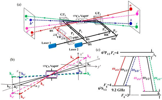
Figure 1.
(a) The experimental layout for spatially structured bidirectional two-color-pump FWM. PBS, polarizing beam splitter; HR, high-reflectivity mirror; BS, 50/50 beam splitter; GT, Glan–Taylor polarizer; λ/4, quarter-wave plate; VR, vortex retarder; black, pump beams; red, blue, green, and pink, the amplified/generated beams a/a′, b/b′, c/c′, and d/d′, respectively. The backward-propagating fields are marked with a prime to distinguish them from the forward-propagating fields. (b) The spatial momentum diagram of the optical field with input pumps k1, k2, k1′, and k2′, and FWM output beams ka, kb, kc, kd, ka′, kb′, kc′, and kd′. (c) The relevant energy-level scheme when using the 133Cs D1 line.
To facilitate the natural spatial separation of the multiple output fields, the five input fields are arranged so that they do not all lie in the same plane. As shown in Figure 1b, the pump beam P1′(P2′) propagates collinearly in the opposite direction to P1 (P2). Specifically, P1 propagates along the z direction; P2 propagates in the same direction as P1 within the y-z plane, while the seed field a propagates in the same direction as P1 within the x-z plane. All five input fields intersect at the center of the vapor cell, with crossing angles of 4 mrad between the P1/1′ and a fields and 5 mrad between the P1/1′ and P2/2′ fields. The e−2 full widths of the pump beams (P1, P1′, P2, and P2′) are approximately 1.3 mm, and that of the seed beam is about 430 µm, measured at the cell center. According to the phase-matching relations, the spatial momenta of all fields ki (i = 1, 1′, 2, 2′, a, a′, b, b′, c, c′, d, d′) are oriented in a manner consistent with Figure 1b. The experimental measurement of frequencies for output fields reveals that ωa = ωa′ = ωb = ωb′ = ω1 = ω1′ and ωc = ωc′ = ωd = ωd′ = ω2 = ω2′. Based on these frequency relationships, all fields involved in this FWM system are represented on the energy-level diagram shown in Figure 1c, where Δ1 =ω1 − ω4↔4 is the single-photon detuning of the pump field P1 or P1′ deviating from the resonance transition of |Fg = 4⟩ ↔ |Fe =4⟩ (similarly Δ2 = ω2-ω3↔4); δ = Δ1 − Δ2 is the two-photon detuning. The frequency separation between the two ground states |Fg = 3⟩ and |Fg = 4⟩ for cesium is 2π × 9.2 GHz.
3. Generation of Four-Pair Output Beams and Their Gain Spectra
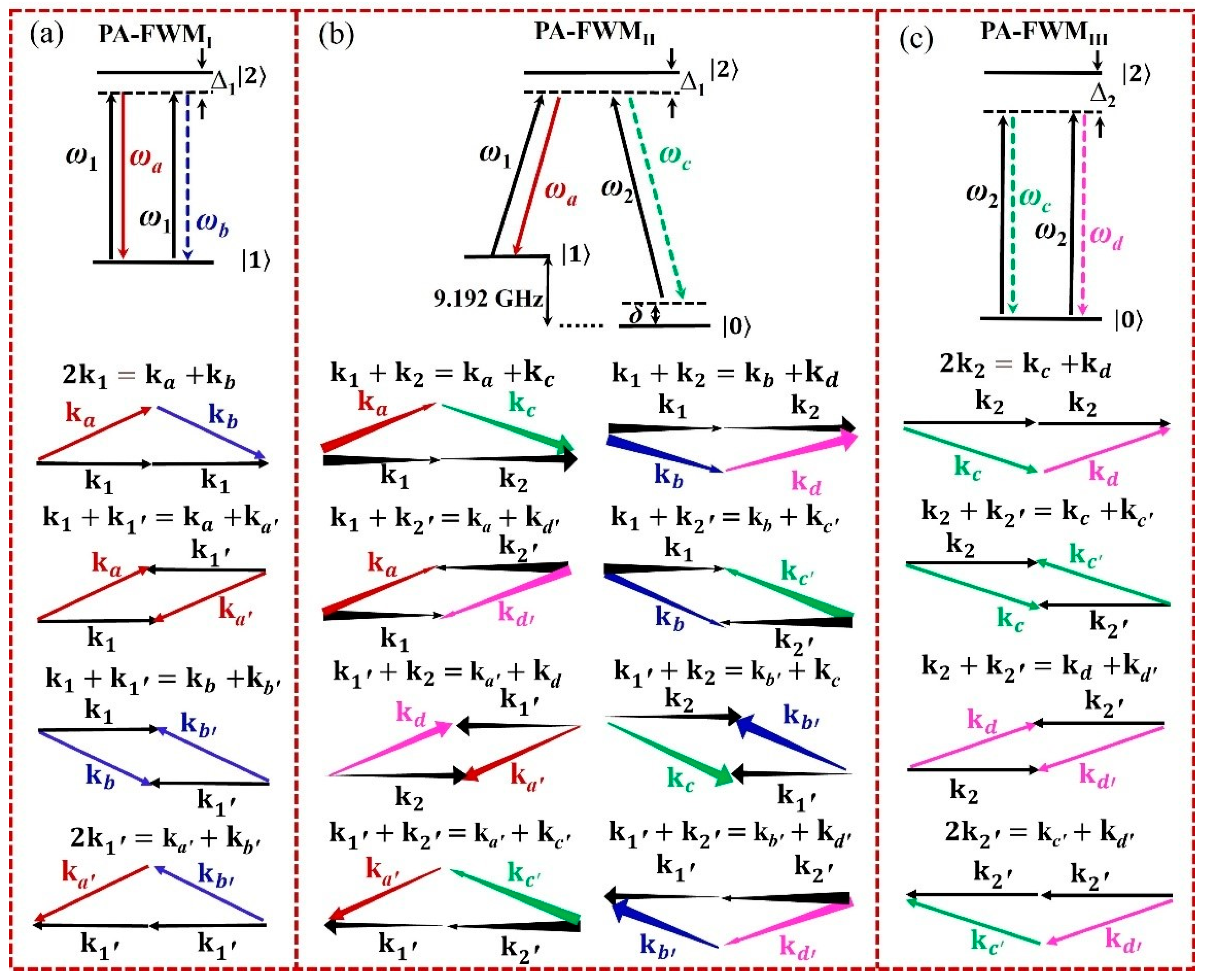
To offer an intuitive physical picture for understanding the generation of new optical fields, Figure 2 presents the relevant energy-level configurations and phase-matching geometries. The three hyperfine energy states |Fg = 3⟩, |Fg= 4⟩, and |Fe =4⟩ of cesium atoms in Figure 1c are relabeled sequentially as |0⟩, |1⟩, and |2⟩, respectively. We propose that the amplification or generation of these four pairs of beams arises from 16 parametric amplification FWM (PA-FMW) processes, which can be categorized into three types of energy-level pathways: degenerate PA-FWMI between energy levels |1⟩ and |2⟩, non-degenerate PA-FWMII within a Λ-type configuration consisting of the two ground levels |0⟩, |1⟩, and the excited level |2⟩, and degenerate PA-FWMIII between energy levels |0⟩ and |2⟩.
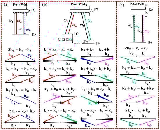
Figure 2.
Energy-level configurations of FWM occurring in the spatially structured bidirectional two-color pump scheme and the corresponding k-vector diagrams displaying the phase-matching in each configuration. (a) PA-FWMI; (b) PA-FWMII; (c) PA-FWMIII. Varying arrow thickness in (b) is used to indicate the direction of vectors entering or exiting the plane of the page.
Each energy-level pathway contains several distinct phase-matching geometries, corresponding to multiple distinct FWM processes. For example, once the phase-matching condition is satisfied, four successive PA-FWMI processes will take place accompanied by the generation of four-mode output (a, a′, b, b′), as shown in Figure 2a. These processes are governed by the conditions , , , and , with energy transfer characterized by the corresponding Liouville perturbation chains , , , and . Where Ωi above the arrow denotes the absorption of a photon from the field, while its conjugate term represents the process of radiating a photon. (with i = 1, 1′, 2, 2′, a, a′, b, b′, c, c′, d, d′) is the Rabi frequency for the optical field with the complex electric field amplitude Ei, the corresponding transition dipole moment , and the reduced Planck constant . ρmn (with m, n = 0, 1, 2) denotes the density matrix elements of the system. The processes can be detailed as follows: two forward pump photons P1 interact with the seed field a inside the vapor cell, leading to the amplification of one photon a and the simultaneous generation of one photon b; furthermore, a forward P1 photon and a backward P1′ photon can also interact with the seed field a, resulting in the amplification of one photon a together with the concurrent generation of one photon a′; the newly generated beam b (or a′) can subsequently act as a seed field to interact with either pump beam P1 or P1′, ultimately producing the new beam b′ (or further amplifying beam a). Based on the PA-FWMI, turning on the pump beams (P2 and P2′) and meeting the phase-matching condition can trigger a sequence of eight successive non-degenerate PA-FWMII processes, thereby generating an eight-mode output (a, a′, b, b′, c, c′, d, d′). As illustrated in Figure 2b, these processes satisfy , , , , , , , and , respectively. Energy transfer in each case is realized via the corresponding perturbation chain , , , , , , or . In addition, four successive degenerate PA-FWMIII processes contribute to the generation of (c, c′, d, d′). As shown in Figure 2c, they meet the phase-matching conditions , , , and , and can be expressed by the following perturbation chains:, , , and . It should be noted that the phase-matching diagrams under the PA-FWMII process differ from those of PA-FWMI and PA-FWMIII. This is because the beams (P1/1′, P2/2′, a, a′, b, b′, c, c′, d, d′) do not lie in the same plane; the variation in arrow size in the diagrams indicates the vectors entering or exiting the plane of the page.
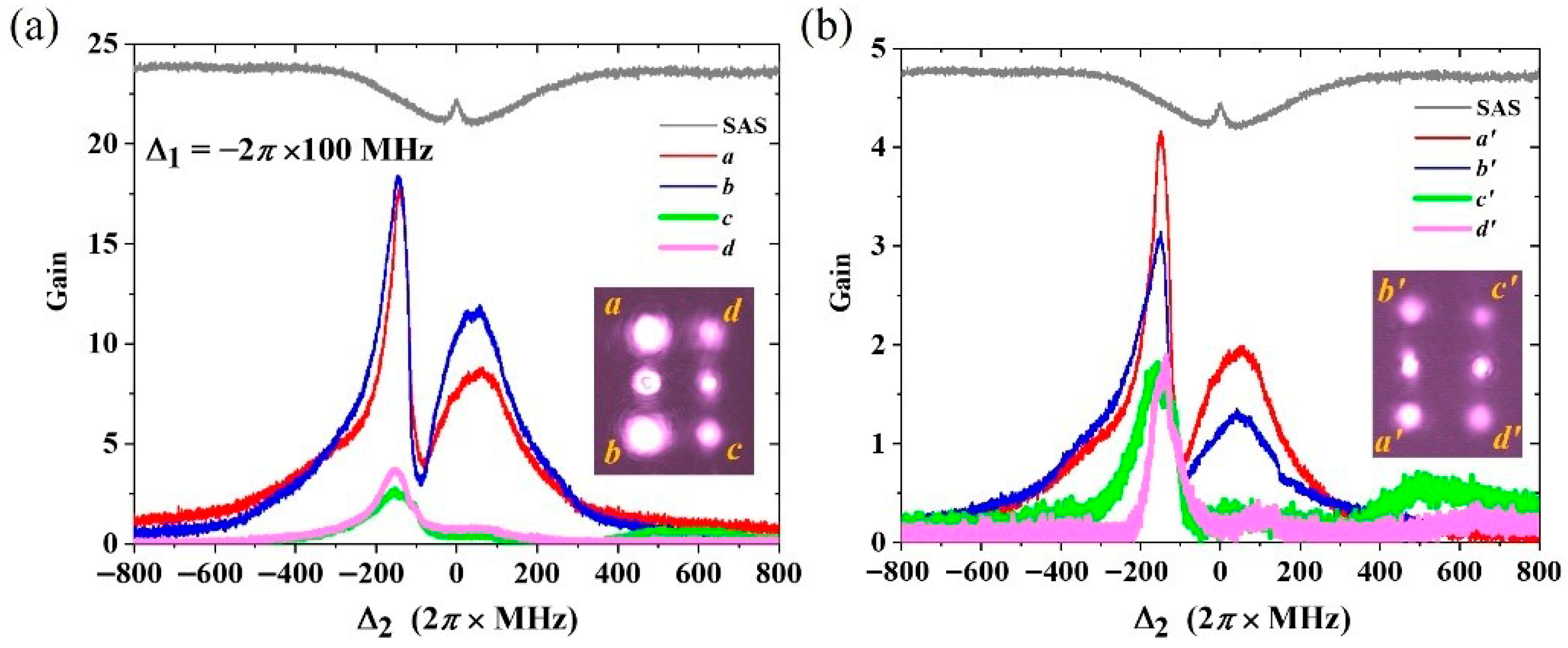
For the Gaussian mode case, we quantitatively measure the FWM optical gain for the four pairs of output fields using eight balanced photodetectors. The optical gain is defined as the ratio of the generated beam’s output power to the seed beam’s input power. The gain spectra shown in Figure 3 are acquired as follows: the frequencies of P1/1′ and beam a are fixed with a specific single-photon detuning . Concurrently, the frequency of the P2/2′ beams is scanned across a ±600 MHz range centered on the |Fg = 3⟩ ↔|Fe = 4⟩ resonance by tuning the external-cavity length of Laser 2. The forward- and backward-propagating fields are displayed in Figure 3a,b, respectively, with the red, blue, green, and pink curves corresponding to the a/a′, b/b′, c/c′, and d/d′ fields. The two pairs of beams a/a′ and b/b′ exhibit significantly higher gain compared to c/c′ and d/d′. This is also clearly evident from the intensity patterns in the corresponding illustrations of Figure 3. The observation can be explained as follows: the generation of a/a′ and b/b′ originates from the processes of PA-FWMI and PA-FWMII, whereas the generation of c/c′ and d/d′ results from the processes of PA-FWMII and PA-FWMIII. Our previous study [38] demonstrated that under identical experimental conditions for the 133Cs D1 line, the degenerate FWM efficiency is significantly higher for |Fg = 4⟩ ↔|Fe = 4⟩ (i.e., |1⟩ ↔ |2⟩ for PA-FWMI) transition than for the |Fg = 3⟩ ↔|Fe = 4⟩ (i.e., |0⟩ ↔ |2⟩ for PA-FWMIII) transition. This difference arises because the atomic coherence among Zeeman sublevels in the ground state is stronger for the |Fg = 4⟩ ↔|Fe = 4⟩ transition. Please note that the two bright spots in the middle row of intensity patterns (i.e., illustrations in Figure 3) are attributed to leakage of the vertically polarized pump beams, which results from the incomplete extinction of the GTs. To account for this, these leaked pump beams are subtracted from all subsequent intensity patterns.
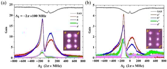
Figure 3.
The FWM gain spectra obtained by scanning the frequency of P2/2′, with the illustrations showing the beams’ pattern observed on the optical screens. (a) the forward-propagating output fields (a, b, c, d). (b) The backward-propagating output fields (a′, b′, c′, d′). The gray curve is the saturated absorption spectrum for the transition of |Fg = 3⟩↔|Fe = 4⟩. The red, blue, green, and pink curves are the gain spectra for beams a/a′, b/b′, c/c′, and d/d′, respectively. Experimental parameters: atom temperature ; the input optical power Pi (with i = 1, 1′, 2, 2′, a) is , , ; the single photon detuning is set to be .
To analyze the envelope shape of the gain spectra, we consider the energy conservation conditions governing the multiple FWM processes. Taking two representative processes as examples, the energy conservation condition for a PA-FWMI process is , and that for a PA-FWMII process is . These conditions imply that PA-FWMI occurs when , while PA-FWMII occurs when . In our experiment, is always satisfied, since P1/1′ and a are derived from the same laser. Consequently, the beam pairs (a, a′) and (b, b′) maintain considerable gain over a broad frequency detuning range for . Notably, this PA-FWMI process is influenced by the dressing effect from the strong pumping fields P2 and P2′. The excited state |2⟩ is then split into two dressed levels |±⟩, which are detuned from the original level |2⟩ by amounts (here, ). The energy conservation conditions are also affected as a result. The density matrix element related to this PA-FWMI process is dressed to be
where is the relaxation coefficient between levels and . The FWM gain scales with . Therefore, the gains for beam pairs (a, a′) and (b, b′) are expected to reach maximum at and minimum at . Equivalently, with fixed at , the gain peak occurs at when is varied. This theoretical expectation is confirmed by the experimental gain curves in Figure 3 (see the red and blue curves): one peak appears at as well as one dip appears at when pumping power and . The other gain peaks at for beam pairs (a, a′) and (b, b′) corresponds to the improved PA-FWMI process due to the optical pumping of fields P2 and P2′. As a result, the PA-FWMII process also moves to the window of instead of , see the green and pink gain curves for beam pairs (c, c′) and (d, d′). It shows that the multiple FWM processes take place synchronously in the window , with gain peak values of , , , , , , , and , respectively. In other words, pumped by a total power of 320 mW, the eight channels collectively generate a net power of 3.689 mW (after deducting the 70 μW seed power), corresponding to a pump-to-generated-wave conversion efficiency of approximately 1.15%. Experimentally, this conversion coefficient can be further improved by optimizing parameters such as the atomic vapor cell temperature, beam waist sizes, and frequency detuning. Notably, under stable experimental conditions—i.e., with constant parameters such as atomic temperature, pump power, beam waist size, intersection angle, and single-photon detuning—the gain profile of the eight FWM signals exhibits good temporal stability. This stability ensures that each channel maintains a clear and consistently bright spatial pattern, thereby supporting high-fidelity data acquisition in experimental observations. Furthermore, due to the non-collinear geometry and carefully chosen beam intersection angles, all output beams are well separated at the observation plane under FWM phase-matching constraints. Spatial overlap between channels is thus negligible, effectively suppressing crosstalk in spatial modes, OAM modes, and frequencies. The remaining possible crosstalk is mainly power and phase noise crosstalk, arising from gain competition among multiple FWM processes sharing the same pump beams. This competition couples different FWM-generated channels, causing intensity and phase crosstalk through refractive index fluctuations, which in turn distorts the spiral phase structure of the vortex beams.
4. Multichannel Vortex Beams Generator
Building on this approach, we demonstrate the parallel generation of multiple vortex beams emerging from both sides of a single 133Cs vapor cell. This is accomplished by incorporating a vortex-generation section [shown in the purple dashed box in Figure 1a] to convert one or more input optical fields into the Laguerre–Gaussian mode. Guided by the principle of OAM conservation (summarized in Table 1), the OAM is coherently transferred to multiple output beams through cascaded FWM processes as presented in Figure 2. Consequently, the OAM of the output vortex beams can be flexibly tuned. In essence, the system operates as a multichannel OAM processor, where the OAM values of the pump and seed beams act as fundamental computational units. Through 16 FWM processes, algebraic operations are efficiently performed on these OAM values, resulting in the parallel generation of a series of new vortex beams whose OAM values are linked to the original inputs via well-defined mathematical relations.

Table 1.
A summary of OAM conservation relations for all 16 FWM processes.
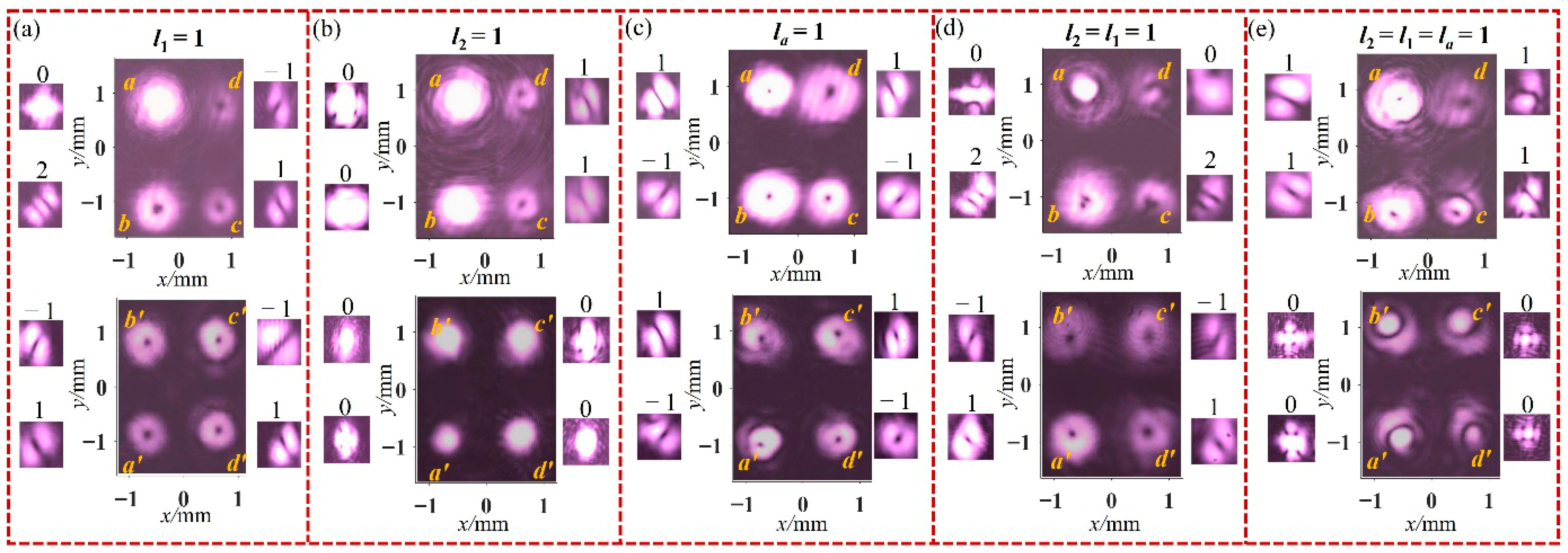
To experimentally verify the OAM of the FWM-generated beams, we employ the tilted lens method [39]. For a Laguerre–Gaussian beam carrying an OAM of l, this method produces a self-interference pattern containing |l| high-contrast dark stripes. The orientation of these stripes depends on the sign of l: they are aligned along the +45° direction for l > 0, and along the –45° direction for l < 0. We first consider the case where only the pump beam P1 is modulated into mode with OAM , while the other four input beams are all Gaussian beams without OAM; the resulting output beams are shown in Figure 4a. In this case, beam a remains a Gaussian profile—its self-interference pattern shows no dark stripes—whereas the other seven output beams exhibit doughnut-shaped hollow profiles, confirming that each carries OAM with , , and , consistent with the OAM conservation algebra. Subsequently, we modulate only the pump P2 or only the seed beam a into mode, with the resulting intensity patterns and tilted lens detection images shown in Figure 4b,c. When only the pump beam P2 is modulated, OAM is transferred exclusively to beams c and d, while all others retain Gaussian profiles. In contrast, modulating only the seed beam a results in the successful replication and transfer of its OAM to each of the generated beams with and .
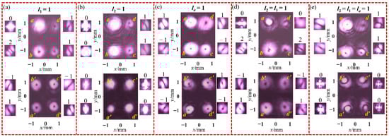
Figure 4.
Intensity patterns and corresponding tilted lens detection images of eight-channel vortex beam outputs under bidirectional two-color pumping for five input cases, where different input beams are modulated into mode with OAM l = 1: (a) only pump beam P1, (b) only pump beam P2, (c) only seed beam a, (d) both beams P1 and P2, (e) beams P1 and P2, and the seed beam a.
The above experiments are performed employing only a single vortex input. We further investigate cases in which multiple vortex beams are simultaneously incident on the atomic vapor cell. For instance, when both the forward pump beams P1 and P2 are modulated into mode, the output beams (a, d) retain Gaussian profiles with while the other six beams exhibit vortex characteristics with OAM , , and [Figure 4d]. Furthermore, when all three forward-propagating inputs (P1, P2, and seed beam a) are modulated into mode, the four forward-generated beams show identical phase distributions with OAM , whereas all four backward-generated beams display Gaussian modes [Figure 4e]. For clarity, the deterministic algebraic relations governing OAM transfer between input and output beams for the five cases described in Figure 4 are summarized in Table 2. It should be noted that this table covers only a subset of possible configurations (modulation of input beams P1, P2, and a). Notably, our experimental system possesses a more capable setup—comprising five independently programmable input channels (P1, P2, P1′, P2′, and a) and supporting a wider selection of input OAM states—thereby enabling more flexible control over the output beams’ OAM.
Table 2.
The OAM algebraic relation between input and output beams for experiment results in Figure 4.
Beyond the flexible control over the OAM of the FWM-generated beams, the number of vortex beam channels is also independently tunable. The spatially structured pump configuration investigated in this work consists of four distinct pump beams. This arrangement enables the manipulation of both the output channel count and the spatial distribution of the generated vortex beams by selectively switching off one or more pump beams, as detailed in Figure 5 and Figure 6. Subsequently, under the condition of modulating only the seed beam a into the mode with OAM , we analyze the dependence of the number of generated vortex beam channels on the number of pump beams by adjusting the latter.
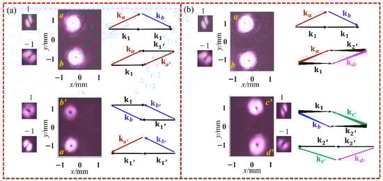
Figure 5.
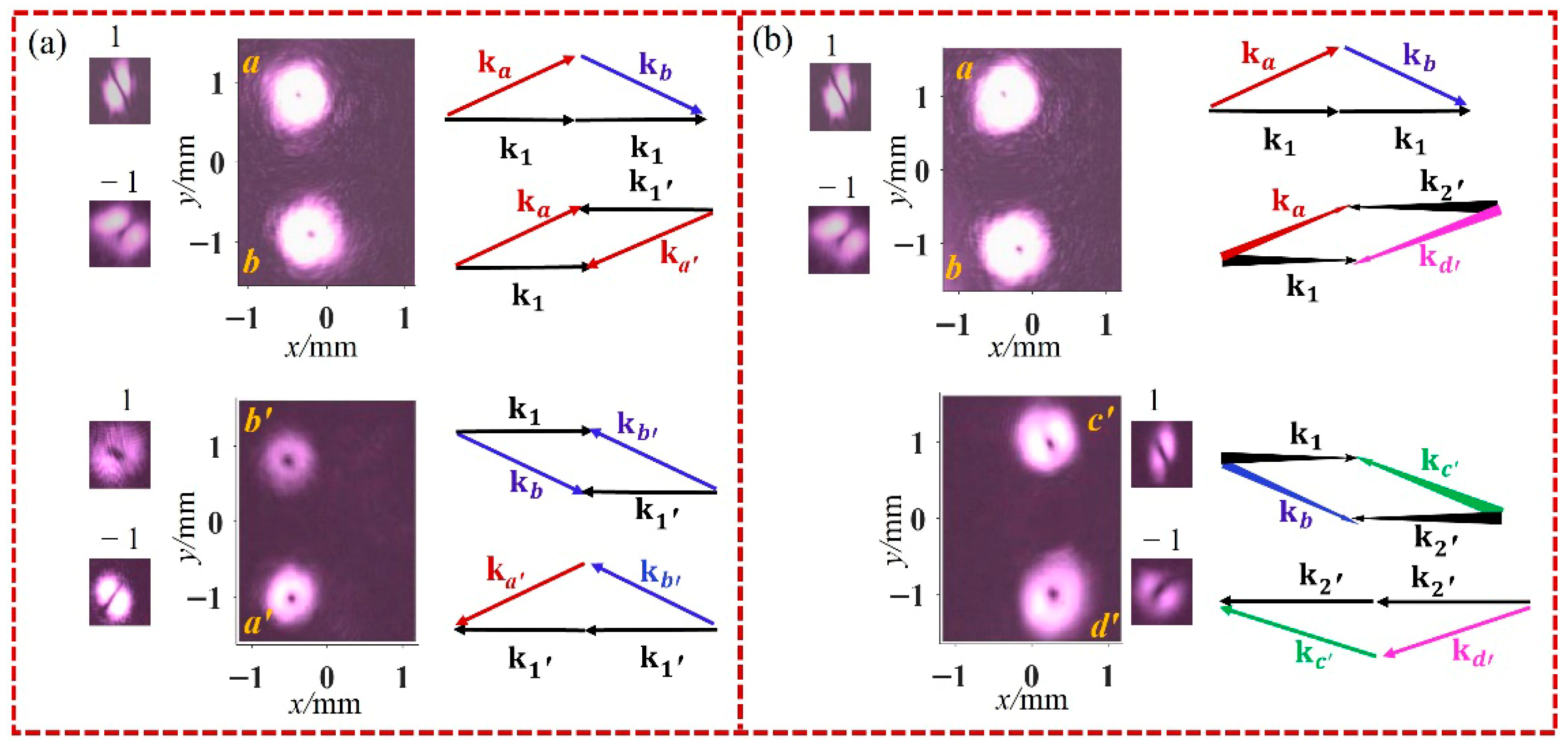
Four-channel vortex beam outputs under bidirectional single-pump configuration with the seed beam in the mode. (a,b) Measured intensity patterns, corresponding tilted lens detection images, and phase-matching conditions (closed wavevector diagrams) for the involved FWM processes for (a) P1 & P1′ and (b) P1 & P2′ pumping schemes.
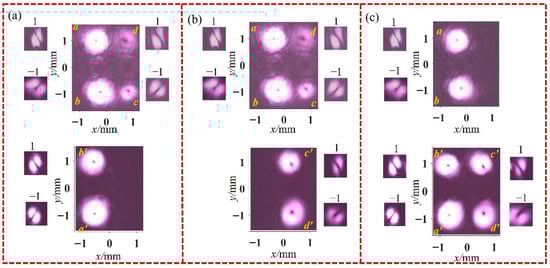
Figure 6.
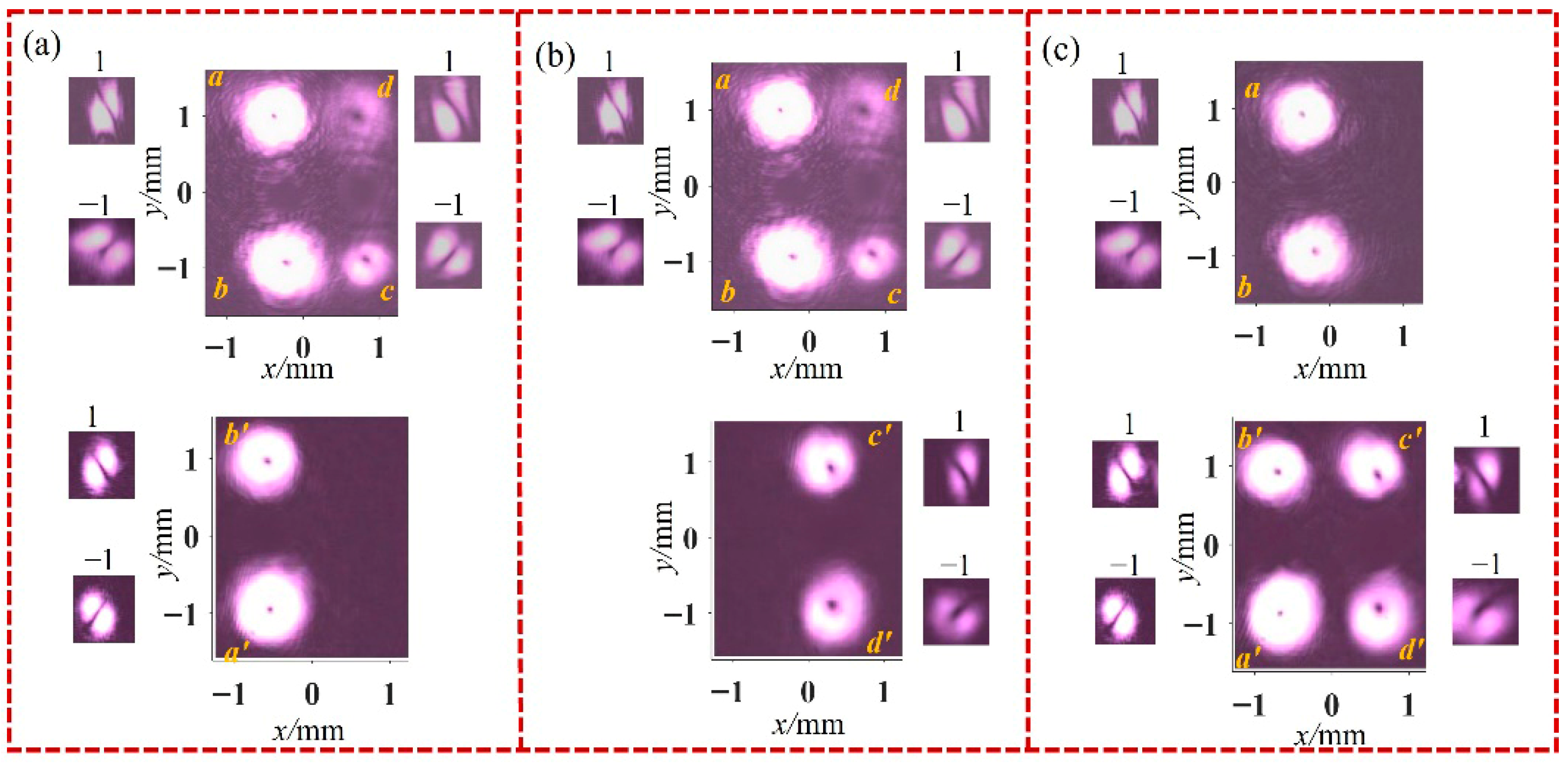
Intensity patterns and corresponding tilted lens detection images of six-channel vortex beam outputs under a single pump on one side and a two-color pump on the opposite side configuration, with the seed beam in the mode. The corresponding pumping schemes are: (a) P1 & P2 & P1′, (b) P1 & P2 & P2′, and (c) P1 & P1′ & P2′.
We first investigate vortex FWM in a bidirectional single-pump configuration employing only one pump beam in each propagation direction. The intensity patterns of the generated beams and their corresponding tilted lens detection images are presented in Figure 5. Reducing the number of pump beams by two decreases the number of generated vortex beam channels to four. For instance, when both the forward pump P2 and the backward pump P2′ are switched off, only the forward beams (a, b) and the backward beams (a′, b′) are observed. As shown in Figure 5a, their measured OAM values are , and . This is because, under the pumping scheme comprising P1 and P1′, only four PA-FWMI processes satisfy the phase-matching conditions , , , and occur within the system. Guided by the corresponding OAM conservation relations, these FWM processes transfer the OAM of the seed beam to these four output beams. Similarly, when the forward pump P2 and backward pump P1′ are switched off, only the forward beams (a, b) and the backward beams (c′, d′) are observed, with OAM values of , and , as shown in Figure 5b. In this configuration, the four FWM processes, governed by the phase-matching conditions of , , , and , occur within the system under the pumping of P1 and P2′.
Based on this observation, we predict that three pump beams can generate six vortex beam channels, and this prediction is subsequently confirmed experimentally. By selectively switching off the backward pumps P2′ and P1′, as well as the forward pump P2, we observe the resulting output vortex beams on both sides of the vapor cell. The corresponding intensity patterns and tilted lens detection images are presented in Figure 6. These results clearly demonstrate that reducing the number of pump beams by one decreases the number of generated beam channels by two. To illustrate intuitively how the number of pump beams governs the output vortex channels and to present the algebraic input-output OAM relations among the multiple vortex beams, we summarize the experimental results from Figure 5 and Figure 6 in Table 3. In the table, a slash (/) denotes that the corresponding optical channel is switched off. It is noteworthy that, except for the forward pump P1—which must remain on to participate in the FWM process (when the seed light is a)—all other pump channels can be independently switched on or off. This capability highlights the system’s excellent controllability in terms of both channel count and spatial distribution.
5. Conclusions
We demonstrate an experimental scheme for a multichannel vortex beam generator based on spatially structured bidirectional two-color-pump FWM in a single 133Cs vapor cell. Specifically, to maximize spatial multiplexing, both sides of the cell are exploited by precisely engineering the propagation directions, frequencies, and OAM states of five input beams (four pump beams and one seed beam). This configuration establishes a nonlinear interaction region supporting up to 16 concurrent multiple phase-matching conditions, thereby enabling the parallel generation of eight spatially separated vortex beam channels (four forward and four backward). The OAM states of the output beams are governed by deterministic algebraic conservation relations: through multiple nonlinear FWM processes, the system effectively performs “algebraic operations” on the OAM of the pump and seed beams, producing a series of new vortex beams whose OAM values are linked to the inputs by well-defined mathematical relations. This enables programmable control over the output OAM via flexible combinations of the input OAM modes. Crucially, the number of output channels can be linearly controlled by selectively switching off pump beams: each deactivated pump beam reduces the channel count by two, as confirmed experimentally. This capability to control the activated FWM processes, combined with the flexible OAM manipulation, demonstrates outstanding command over the vortex beam properties—including OAM states, channel numbers, and spatial arrangement.
In contrast to the bidirectional single-pump work by Xin Li et al. [37], our design achieves better spatial multiplexing around the vapor cell, exciting up to 16 FWM processes and consequently doubling the number of generated beams. Benefiting from the increased number of pump beams, our scheme achieves greater flexibility in both channel count and OAM mode controllability. In addition, the involvement of multiple energy-level configurations enables richer energy conservation relations. These advantages—scalability in channel number and mode complexity—highlight the potential of our approach for advanced photonic applications requiring high-dimensional encoding. In principle, the channel count in our scheme is scalable by adding pump beams. However, further scaling is limited by: (i) spatial constraints of the vapor cell end-window and phase-matching conditions; (ii) gain competition among multiple FWM processes, reducing per-channel power and introducing crosstalk; (iii) increased pump power requirements; and (iv) reliance on distinct energy-level configurations—channel expansion must match the atomic structure, unlike geometry-tuned schemes [40]. Future improvements via dynamic beam shaping and parameter optimization offer pathways toward higher channel counts while maintaining compactness. Our work thus provides an integrated and controllable physical platform for multichannel vortex generation. It further highlights the promising potential of combining bidirectional structured pumping with atomic systems to expand the dimensionality of optical fields and enhance spatial multiplexing capacity, thereby laying a valuable foundation for advanced applications in multidimensional communications, distributed quantum networks, and integrated photonic systems.
Author Contributions
Conceptualization, D.W. and M.-Y.B.; methodology, H.-T.Z. and J.-X.Z.; software, M.-Y.B. and Z.-Y.G.; validation, M.-Y.B. and Z.-Y.G.; formal analysis, D.W. and L.-H.H.; investigation, D.W. and M.-Y.B.; resources, L.-H.H. and H.-T.Z.; data curation, M.-Y.B. and Z.-Y.G.; writing—original draft preparation, D.W. and M.-Y.B.; writing—review and editing, D.W. All authors have read and agreed to the published version of the manuscript.
Funding
This work was supported by National Natural Science Foundation of China (12474266, 92065108), and the Fund for Shanxi “1331” Project Key Subjects Construction.
Data Availability Statement
The original contributions presented in this study are included in the article. Further inquiries can be directed to the corresponding authors.
Conflicts of Interest
The authors declare no conflicts of interest.
References
- Allen, L.; Beijersbergen, M.W.; Spreeuw, R.J.C.; Woerdman, J.P. Orbital angular momentum of light and the transformation of Laguerre-Gaussian laser modes. Phys. Rev. A 1992, 45, 8185. [Google Scholar] [CrossRef]
- Stoyanov, L.; Topuzoski, S.; Paulus, G.G.; Dreischuh, A. Optical vortices in brief: Introduction for experimentalists. Eur. Phys. J. Plus 2023, 138, 702. [Google Scholar] [CrossRef]
- Wang, W.; Zhang, K.; Jing, J. Large-scale quantum network over 66 orbital angular momentum optical modes. Phys. Rev. Lett. 2020, 125, 140501. [Google Scholar] [CrossRef] [PubMed]
- Wang, J.; Yang, J.Y.; Fazal, I.M.; Ahmed, N.; Yan, Y.; Huang, H.; Ren, Y.; Yue, Y.; Dolinar, S.; Tur, M.; et al. Terabit free-space data transmission employing orbital angular momentum multiplexing. Nat. Photonics 2012, 6, 488–496. [Google Scholar] [CrossRef]
- Li, S.; Pan, X.; Ren, Y.; Liu, H.; Yu, S.; Jing, J. Deterministic generation of orbital-angular-momentum multiplexed tripartite entanglement. Phys. Rev. Lett. 2020, 124, 083605. [Google Scholar] [CrossRef] [PubMed]
- Liu, S.; Lou, Y.; Jing, J. Orbital angular momentum multiplexed deterministic all-optical quantum teleportation. Nat. Commun. 2020, 11, 3875. [Google Scholar] [CrossRef]
- Liu, S.; Lv, Y.; Wang, X.; Wang, J.; Lou, Y.; Jing, J. Deterministic all-optical quantum teleportation of four degrees of freedom. Phys. Rev. Lett. 2024, 132, 100801. [Google Scholar] [CrossRef]
- Lou, Y.; Lv, Y.; Wang, J.; Liu, S.; Jing, J. Orbital angular momentum multiplexed deterministic all-optical quantum erasure-correcting code. Phys. Rev. Lett. 2024, 132, 040601. [Google Scholar] [CrossRef]
- Zhao, M.; Gao, X.; Xie, M.; Zhai, W.; Xu, W.; Huang, S.; Gu, W. Measurement of the rotational Doppler frequency shift of a spinning object using a radio frequency orbital angular momentum beam. Opt. Lett. 2016, 41, 2549–2552. [Google Scholar] [CrossRef]
- Muñoz-Pérez, F.M.; Ferrando, V.; Furlan, W.D.; Castro-Palacio, J.C.; Arias-Gonzalez, J.R.; Monsoriu, J.A. Multiplexed vortex beam-based optical tweezers generated with spiral phase mask. Iscience 2023, 26, 106468. [Google Scholar] [CrossRef]
- Yu, J.; Yang, Y.; Tong, S.; Zhang, Z.; Zhou, M.; Long, H.; Li, S. Propagation characteristics and multi-particle trapping of Gaussian beams double-modulated by sine-cosine power-exponent-phase vortices. Opt. Commun. 2025, 566, 132468. [Google Scholar] [CrossRef]
- Liu, H.; Liu, J.; Dou, J.; Li, B.; Hu, Y. Controllable optically induced rotation based on rotationally-symmetric power-exponent-phase vortex beams with high-efficiency. Opt. Laser Technol. 2025, 186, 108782. [Google Scholar] [CrossRef]
- Shafiq, M.; Quanrun, F.; Du, C.; Bilal, A.; Syamala, M.; Muniyandy, E. Multiplexing techniques for future fiber optic communications with spatial multiplexing. Opt. Quantum Electron. 2024, 56, 330. [Google Scholar] [CrossRef]
- Xie, X.; Chen, Y.; Yang, K.; Zhou, J. Harnessing the point-spread function for high-resolution far-field optical microscopy. Phys. Rev. Lett. 2014, 113, 263901. [Google Scholar] [CrossRef] [PubMed]
- Meier, M.; Romano, V.; Feurer, T. Material processing with pulsed radially and azimuthally polarized laser radiation. Appl. Phys. A 2007, 86, 329–334. [Google Scholar] [CrossRef]
- Chen, S.; Li, J.; Ueda, K. Generation of nanosecond pulsed azimuthally and radially polarized beams with an actively Q-switched rotating disk laser. Appl. Phys. Lett. 2021, 119, 091102. [Google Scholar] [CrossRef]
- Zhao, H.; Zhao, R.; Liu, Q.; Sheng, Y.; Xu, T. High-Capacity Near-Infrared Optical Vortex Sorting and Detection by Nonlinear Dammann Vortex Grating. Photonics 2025, 12, 532. [Google Scholar] [CrossRef]
- Rosales-Guzmán, C.; Bhebhe, N.; Forbes, A. Simultaneous generation of multiple vector beams on a single SLM. Opt. Express 2017, 25, 25697–25706. [Google Scholar] [CrossRef] [PubMed]
- Popiołek-Masajada, A.; Kurzynowski, P.; Litwin, P.; Masajada, J. One-way generation of vector beams using the spatial light modulator. Opt. Laser Technol. 2026, 193, 114375. [Google Scholar] [CrossRef]
- Jin, J.; Pu, M.; Wang, Y.; Li, X.; Ma, X.; Luo, J.; Zhao, Z.; Gao, P.; Luo, X. Multi-channel vortex beam generation by simultaneous amplitude and phase modulation with two-dimensional metamaterial. Adv. Mater. Technol. 2017, 2, 1600201. [Google Scholar] [CrossRef]
- Sun, Q.A.; Tian, Y.; Yu, H.; Wang, C.; Ma, X.; Liang, K.; Yu, L.; Yang, L. Optical vortices with identical topological charges: Interference couplings and optical gradient forces on plasmonic metasurfaces. Opt. Laser Technol. 2025, 181, 111733. [Google Scholar] [CrossRef]
- Qiao, Z.; Wan, Z.; Xie, G.; Wang, J.; Qian, L.; Fan, D. Multi-vortex laser enabling spatial and temporal encoding. PhotoniX 2020, 1, 13. [Google Scholar] [CrossRef]
- Chen, H.; Li, X.; Cui, Y.; Zhang, B.; Chang, X.; Qi, Y.; Ding, J.; Yan, B.; Wang, Y.; Lu, Z.; et al. Generation of tunable vortex beams from a side-pumped Nd: YAG laser utilizing spot defect mirrors. Opt. Commun. 2024, 563, 130587. [Google Scholar] [CrossRef]
- Daems, D.; Bernard, F.; Cerf, N.J.; Kolobov, M.I. Tripartite entanglement in parametric down-conversion with spatially structured pump. J. Opt. Soc. Am. B 2010, 27, 447–451. [Google Scholar] [CrossRef]
- Wang, S.; Zhang, S.L.; Qiao, H.C.; Li, P.; Hao, M.H.; Yang, H.M.; Xie, J.; Feng, G.Y.; Zhou, S.H. Direct generation of vortex beams from a double-end polarized pumped Yb: KYW laser. Opt. Express 2018, 26, 26925–26932. [Google Scholar] [CrossRef] [PubMed]
- Yuan, J.; Zhang, H.; Wu, C.; Chen, G.; Wang, L.; Xiao, L.; Jia, S. Creation and Control of Vortex-Beam Arrays in Atomic Vapor. Laser Photonics Rev. 2023, 17, 2200667. [Google Scholar] [CrossRef]
- Shen, Y.; Huang, Y.; Yuan, J.; Liang, S.; Du, L.; Zhao, C.; Zhang, Y.; Zhang, Z. Phase difference induced curved photonic lattice in atomic vapors. Front. Phys. 2025, 20, 062201. [Google Scholar] [CrossRef]
- Knutson, E.M.; Cross, J.S.; Wyllie, S.; Glasser, R.T. Phase-sensitive amplification via multi-phase-matched four-wave mixing. Opt. Express 2020, 28, 22748–22754. [Google Scholar] [CrossRef]
- Cai, Y.; Hao, L.; Zhang, D.; Liu, Y.; Luo, B.; Zheng, Z.; Li, F.; Zhang, Y. Multimode entanglement generation with dual-pumped four-wave-mixing of Rubidium Atoms. Opt. Express 2020, 28, 25278–25292. [Google Scholar] [CrossRef]
- Wang, H.; Fabre, C.; Jing, J. Single-step fabrication of scalable multimode quantum resources using four-wave mixing with a spatially structured pump. Phys. Rev. A 2017, 95, 051802. [Google Scholar] [CrossRef]
- Yu, S.; Zhang, K.; Lou, Y.; Liu, S.; Jing, J. Entanglement of Six Orbital Angular Momentum Modes with Reconfigurable Topological Charges. Laser Photonics Rev. 2023, 17, 2201005. [Google Scholar] [CrossRef]
- Wang, D.; Zhang, Y.; Bian, M.; Liu, J.; Huang, L.; Zhou, H.; Zhang, J. Multiple phase-matched resonant four-wave mixing processes in a single hot 133Cs vapor cell via a spatially structured two-beam pump. Opt. Contin. 2025, 4, 1092–1103. [Google Scholar] [CrossRef]
- Pan, X.; Yu, S.; Zhang, K.; Jing, J. Experimental demonstration of complex four-wave mixing processes with pump of orbital-angular-momentum superposition mode. Appl. Phys. Lett. 2024, 124, 161103. [Google Scholar] [CrossRef]
- Wang, D.; Hu, L.Y.; Pang, X.M.; Zhang, J.X.; Zhu, S.Y. Quadripartite entanglement from a double three-level Λ-type-atom model. Phys. Rev. A 2013, 88, 042314. [Google Scholar] [CrossRef]
- Meng, C.; Shui, T.; Yang, W.X. Coherent transfer of optical vortices via backward four-wave mixing in a double-Λ atomic system. Phys. Rev. A 2023, 107, 053712. [Google Scholar] [CrossRef]
- Song, D.; Li, X.; Zhou, H.T.; Xue, J.J.; Li, R.N.; Wang, D.; Yang, B.D.; Zhang, J.X. Optical reciprocity-nonreciprocity-amplification conversion based on degenerate four-wave mixing. J. Opt. Soc. Am. B 2024, 41, 984–991. [Google Scholar] [CrossRef]
- Li, X.; Song, D.; Fan, Y.X.; Miao, R.; Wang, D.; Yang, B.D.; Zhou, H.T.; Zhang, J.X. Spatial-Multiplexed Four-Channel Optical Amplification via Multiple Four-Wave Mixing in a Double-Λ Atomic System. Nanomaterials 2026, 16, 184. [Google Scholar] [CrossRef] [PubMed]
- Zhou, H.T.; Li, R.F.; Dai, Y.P.; Wang, D.; Wu, J.Z.; Zhang, J.X. Angular-momentum-dependent optical gain spectrum based on stimulated degenerate four-wave mixing. J. Phys. B At. Mol. Opt. Phys. 2019, 52, 185002. [Google Scholar] [CrossRef]
- Vaity, P.; Banerji, J.; Singh, R.P. Measuring the topological charge of an optical vortex by using a tilted convex lens. Phys. Lett. A 2013, 377, 1154–1156. [Google Scholar] [CrossRef]
- Liu, S.; Lou, Y.; Jing, J. Experimental characterization of multiple quantum correlated beams in two-beam pumped cascaded four-wave mixing process. Opt. Express 2019, 27, 37999–38005. [Google Scholar] [CrossRef]
Disclaimer/Publisher’s Note: The statements, opinions and data contained in all publications are solely those of the individual author(s) and contributor(s) and not of MDPI and/or the editor(s). MDPI and/or the editor(s) disclaim responsibility for any injury to people or property resulting from any ideas, methods, instructions or products referred to in the content. |
© 2026 by the authors. Licensee MDPI, Basel, Switzerland. This article is an open access article distributed under the terms and conditions of the Creative Commons Attribution (CC BY) license.