Abstract
Multi-channel common-aperture optical systems, which excel at simultaneous multi-spectral information acquisition, are widely used for image fusion. However, complex systems for long-distance multi-band detection suffer from difficulties in assembly and adjustment and light vignetting. To resolve this, the paper proposes a modular design method that splits the optical path into independent modules: the common-aperture optical path adopts an off-axis reflective beam-shrinking structure to extend the focal length and ensure 100% light input, compared with coaxial multi-channel common-aperture systems. The relay optical path of each spectral channel uses a continuous zoom design for smooth detection–recognition switching. Based on the method, a three-channel common-aperture system is developed integrating visible light (VIS), short-wave infrared (SWIR), and mid-wave infrared (MWIR). The modulation transfer function (MTF) and wavefront distribution of the common-aperture optical path approach the diffraction limit. After integration with the relay optical paths, the system, without global optimization, can achieve the following performance: the root mean square (RMS) across the full field of view (FOV) at different focal lengths for each channel is smaller than the detector pixel size (3.45 μm for VIS, 15 μm for SWIR/MWIR); the MTF exceeds 0.2 at the cutoff frequency. Subsequently, the results of the tolerance analysis verify the feasibility of the design for each module and the advantage of the modular layout in the assembly and adjustment of the system. Finally, the paper discusses the influence of parallel plates on the wavefront distortion of the system and proposes optimization thinking using freeform surfaces. The design results of the study validate the feasibility of the modular layout in simplifying the design and assembly of multi-channel common-aperture optical systems.
1. Introduction
In current fields such as national defense surveillance [1], medical imaging [2] and scientific research [3], fused images allow clearer acquisition of scene information, facilitating the extraction of details and features from images [4]. Multi-channel imaging, which integrates spectral information from multiple spectral bands, can achieve complementary information collection and enhanced perceptual capabilities [5], effectively addressing the limitations of single-channel imaging. Additionally, multi-channel optical systems enhance the contrast and accuracy of target details, improve detection capabilities in complex environments, and are particularly suitable for high-resolution imaging tasks in remote sensing, target reconnaissance and astronomy.
Compared to multi-channel split-aperture systems, the channels of multi-channel common-aperture optical systems share a front-end optical path and have consistent entrance pupil positions, significantly improving the integration of the system and the spatiotemporal consistency of each channel [6]. Multi-channel common-aperture optical systems are mainly divided into refractive, reflective, and catadioptric types.
Yiming Ying et al. [7] designed a dual-channel common-aperture optical system using internally reflective lenses, with the visible light (VIS) channel having a focal length of 17 mm and an F-number of 1.7938, and the near-infrared (NIR) channel having a focal length of 17.9 mm and an F-number of 1.8842. Xiao Song et al. [8] developed a three-channel common-aperture optical system based on the transmission theory, including VIS, NIR and mid-wave infrared (MWIR) channels, all with a focal length of 70 mm and F-numbers of 3 and 5. The transmission systems are limited by materials, making it difficult to achieve large apertures and thus unable to obtain long focal lengths.
In recent years, optical imaging has been developing towards long-distance and high-resolution imaging, which has promoted the continuous increase in the aperture and focal length of optical systems [9]. Reflective and catadioptric structures have thus become the main approaches to ensuring that long-focal-length, large-aperture systems are compact and lightweight. Kailin Zhang et al. [10] designed a common-aperture optical system, covering VIS, short-wave infrared (SWIR) and MWIR channels and using a Cassegrain catadioptric structure, with a maximum focal length of 1360 mm and an F-number of 7.10. Lei Zhang et al. [11] added even-order aspheric lenses to the Ritchey–Chretien structure to develop a common-aperture system, which includes VIS and long-wave infrared (LWIR) channels, and a laser ranging channel. This system has a maximum focal length of 300 mm and a maximum entrance pupil aperture of 100 mm. Wei Yue et al. [9] designed a three-channel common-aperture system. The common-aperture optical path adopts a Cassegrain structure, and a dichroic mirror is used to transmit LWIR. Jiadong Yu et al. [12] designed a common-path optical system covering the VIS to SWIR bands, with a focal length of 1680 mm and an entrance pupil diameter of 180 mm. The system, employing an off-axis four-mirror configuration, eliminates central ray obstruction, compared with common-aperture systems based on the Cassegrain configuration and its variants, but has a narrower spectral bandwidth.
The aforementioned methods offer ideas for multi-channel common-aperture optical path design but have two issues: Firstly, the common-aperture and relay paths bear optical power together, increasing system assembly difficulty and limiting upgrades for multi-functionality and multi-spectral compatibility. Secondly, the Cassegrain structure and its variants of wide-spectrum common-aperture optical paths reduce system weight and fold the optical path, but central light obstruction causes energy loss and lower imaging contrast. These problems challenge the application of multi-channel optical systems.
To address the current challenges in multi-channel common-aperture optical systems, the paper proposes a modular layout-based design method. The common-aperture optical path and the relay optical path of each channel are designed as independent modules to achieve optimal image quality, then integrated via beam-splitting elements. The modular design supports the separate assembly and adjustment of each optical path, effectively reducing the overall assembly difficulty of the system. To minimize system energy loss, the common-aperture optical path adopts a design of offsetting aperture stop to solve the light obstruction issue. Furthermore, the paper takes the design of a three-channel common-aperture optical system, covering VIS, SWIR, and MWIR as an example to verify the effectiveness of the proposed method.
2. Modular Optical Path Layout of the Optical System
In traditional multi-channel common-aperture systems, the front-end and relay optical paths are generally designed as an integrated optical path, increasing system assembly difficulty. Based on this, the paper proposes a modular layout. The layout allows for independent design of front-end and relay paths to optimal image quality before overall integration. The modular feature enables separate assembly and adjustment of each path, effectively reducing the overall difficulty in the assembly system. For the design case in the article, the system is divided into five modules: common-aperture optical path, beam-splitting components, and VIS, SWIR and MWIR relay optical paths, as shown in Figure 1. The common-aperture optical path is an all-reflective system, with beam-splitting components near the exit pupil to separate different spectral bands. Each relay optical path is connected in series with the front-end path according to the pupil matching principle [13] to extend the focal length [14]. The common-aperture optical path adopts an off-axis afocal beam-shrinking structure, which does not bear optical power, while enabling flexible matching with infinite-conjugate small-aperture imaging systems to expand into other spectral bands, and the off-axis design ensures a beam obstruction ratio of 0%. The relay optical paths feature a continuous zoom design for smooth switching between detection and recognition.
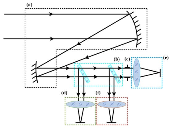
Figure 1.
Modular optical path layout of the three-channel common-aperture optical system. Block (a) shows the common-aperture optical path; block (b) shows the beam-splitting components; block (c) shows the exit pupil of front optical path/the entrance pupil of relay optical path; block (d) shows the VIS relay optical path; block (e) shows the SWIR relay optical path; and block (f) shows the MWIR relay optical path.
Based on the method, the paper designs a three-channel common-aperture optical system covering VIS, SWIR, and MWIR. According to the system technical requirements, as shown in Table 1, and Johnson’s criteria [15], the core optical parameters of the system for each channel, such as focal length and relative aperture and so on, are determined with no less than 95% detection and identification probability, as shown in Table 2.

Table 1.
System technical requirements.
Table 2.
Core optical parameters of each channel.
3. Optical System Design and Results Discussion
3.1. Common-Aperture Optical Path Design
The design of the common-aperture optical path must consider not only the system’s imaging quality but also compactness and assembly difficulty. Compared with three- and four-mirror optical paths, the folded two-mirror path meets compactness requirements while simplifying assembly and adjustment and reducing time costs. Thus, the section uses an off-axis two-mirror system as the initial structure. In the initial design stage, based on the geometric aberration equations of the coaxial structure, the obstruction ratio of the primary mirror, the magnification of the secondary mirror, and conic constants of the primary and secondary mirrors are determined, as shown in Equations Set (1) [16]; a coaxial beam-shrinking system with minimal primary aberrations is designed by selecting appropriate key parameters to reduce the aberration correction difficulty of the off-axis system.
In the set of equations, , , , and represent the third-order aberration coefficients of the system’s spherical aberration, coma aberration, astigmatism, field curvature and distortion, respectively. and represent the conic constants of the primary and secondary mirrors, represents the obstruction ratio of the primary mirror, and represents the lateral magnification of the secondary mirror. By offsetting the aperture stop of the coaxial reflective system, an off-axis reflective system free of central ray obstruction can be obtained, as illustrated in Figure 2. The quantitative relationship between the off-axis distance of the aperture stop and parameters such as the maximum field of view (FOV) of the system can be derived, as expressed in Equation (2).
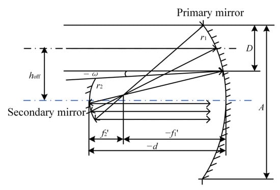
Figure 2.
Relationship between off-axis distance of aperture stop and optical parameters of coaxial reflective system.
In Figure 2 and Equation (2), denotes the optical aperture of the primary mirror in the coaxial system, represents the aperture stop diameter, refers to the vertex distance between the primary mirror and the secondary mirror, stands for the maximum half FOV angle, and indicates off-axis distance of the aperture stop. The result of the optimized design of the common-aperture optical path is shown in Figure 3. The system is designed as an afocal beam-shrinking system, which compresses the aperture of the light beams to 1/3 of the original size. The beam-splitting components divide the outgoing optical path into three channels, with the exit pupil located at the outgoing channels. A plane mirror is introduced between the primary and secondary mirrors to fold the optical path, reducing the total length of the system. Both the primary and secondary mirrors adopt parabolic surfaces. The maximum aperture of the primary mirror is 220 mm, while that of the secondary mirror is 120 mm. The aperture stop positioned at the primary mirror has an off-axis distance of 250 mm.
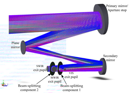
Figure 3.
Common-aperture optical path.
The image quality is evaluated based on the wavefront aberration and the modulation transfer function (MTF). Taking the maximum FOV as an example, Figure 4 shows the wavefront distribution of the common-aperture optical path. According to the Rayleigh criterion, a system approaches the diffraction limit when the peak-to-valley (PV) of the wavefront ≤ λ/4 and the root mean square (RMS) ≤ λ/14 [17,18]. In the figure, the maximum PV is 0.1868λ and the maximum RMS is 0.535λ. Figure 5 presents the MTF curves, where the solid lines represent the tangential direction and the dashed lines represent the sagittal direction. The MTF curves are concentrated and close to the diffraction limit, and the wavefront distribution and MTF curves effectively ensure the imaging quality of the front optical path.
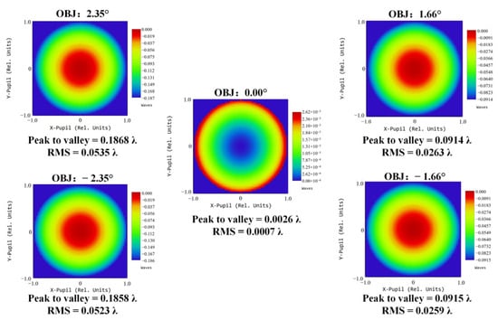
Figure 4.
Wavefront distribution of the common-aperture optical path.
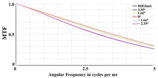
Figure 5.
MTF of the common-aperture optical path.
3.2. VIS Channel Design
Since the common-aperture optical path extends focal length, the quantitative relationship between the optical parameters of the relay optical path and the corresponding optical channel is shown in Equations Set (3).
In the equation set: and represent the focal length and FOV of each spectral band channel; and represent those of the relay optical path for the corresponding channel; and represents the aperture compression ratio of the optical path with common-aperture.
The modular design allows the relay optical paths to be designed as independent imaging lenses. Accordingly, the design and optimization of each spectral band channel is divided into three phases: First, the initial zoom structure is calculated. Secondly, optimization is conducted using the Point Spread Function (PSF) and MTF as evaluation criteria, with the establishment of an optimization evaluation function. Finally, the aberration-corrected relay optical paths are connected in series with the front optical path via the beam-splitting components in accordance with the pupil matching principle to form the complete channel, and the imaging performance of each channel is evaluated.
The design of zoom systems is generally based on the optimization of existing patented structures, which is limited by the selected structural layout and lacks flexibility, and struggles to meet the requirement of placing the entrance pupil in the front row [19]. To address the issue, the paper proposes a calculation method for the initial structure of the zoom systems, based on the four-element zoom principle of Gaussian optics theory [20] and optical design software. Firstly, the zoom principle and its equations are derived theoretically. The system achieves continuous focal length variation with a fixed total length through the linkage of the zoom group and the compensation group. Thus, only the linked groups need to be analyzed; see Figure 6.
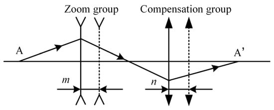
Figure 6.
Conjugate imaging of zoom group and compensation group in zoom system.
In the figure, the zoom group and compensation group prior to movement are indicated by solid lines, whereas those after movement are indicated by dashed lines. the image of the fixed front group is the object A of the zoom group, and the object of the fixed post group is the image A’ of the compensation group; and represent the displacements of the zoom group and compensation group, respectively. The zoom group moves to change the focal length of the system, while the compensation group moves to offset the image plane displacement. To achieve image plane stability during zooming, the sum of image plane displacements must be 0. According to Gaussian optic theory, the relationship is given in Equation (4).
In the equation: and represent the magnifications of the zoom group and the compensation group, respectively. By combining the differential relationship between magnification and object/image distance within Gaussian optics theory, the zoom equations set for the four-element continuous zoom optical system can be derived, as shown in Equations Set (5).
In the set of equations, and denote the focal lengths of the zoom group and the compensation group, respectively. Based on the system focal length and zoom ratio, initial conditions (e.g., short/long focal magnifications of the zoom group, short focal magnification of the compensation group) are set, and the equations set is solved via mathematical software to obtain the compensation group’s focal length and the displacement of the linkage group. The object plane of the system is at infinity and the image plane is at the back focal plane. Because a negative-power compensation group would result in a larger aperture and smaller curvature of the front lens group, increasing optimization difficulty, a positive-power solution is selected. On the basis, the distances between the fixed front and post groups and the linkage group, as well as the back focal length, are set. The focal lengths and zoom intervals of the four lens groups are derived using Gaussian optics theory. An ideal paraxial optical path model based on these parameters is established in optical design software, and the rationality of the initial structural parameters is verified by the smoothness of the zoom curve. After confirming the zoom parameters, the ideal paraxial surfaces are replaced with actual lenses, and the relay optical path is globally optimized using PSF and MTF as evaluation criteria to finally obtain the actual optical path model.
The 5× VIS relay optical path is designed by the above method. The detector is a CMOS camera with a resolution of 1280 × 1024 and a pixel size of 3.45 μm. Table 3 presents the zoom parameters of the optical path and Figure 7 shows the optical path with a focal length of 23–115 mm, an FOV of 2.82–14.10° and a total length of 123.0 mm, including 12 lenses. All four groups of the path adopt lens combinations of single lens and double cemented lenses, which can effectively reduce major aberrations such as high-order spherical aberration and chromatic spherical aberration. Figure 8 shows the VIS channel formed by cascading the optical path with the common-aperture optical path, with a focal length of 69–345 mm and an FOV of 0.94–4.70°.
Table 3.
Zoom parameters of the VIS relay optical path (unit: mm).
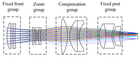
Figure 7.
Optical path of the 5× VIS relay system.
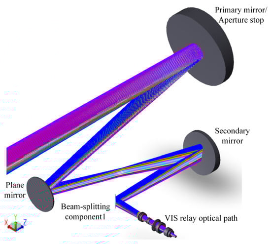
Figure 8.
Optical path of the VIS channel.
In Figure 8, VIS rays are reflected by the front-end system to the VIS relay system via beam-splitting component 1, forming an image on the detector. The spot diagrams of the channel are presented in Figure 9. The root mean square (RMS) of the spots in the entire FOV ranges from 0.734 to 3.282 μm, which is smaller than the detector’s pixel size, effectively ensuring the quality of the optical system imaging. The cutoff frequency, calculated based on the detector’s pixel size, is 145 lp/mm. Figure 10 shows the MTF curves of the VIS channel at different focal lengths, where solid lines represent the tangential direction FOV and dashed lines represent the sagittal direction FOV. The results indicate that the MTF curves of the central FOV are nearly close to the diffraction limit, and the MTF values of the edge FOV are all above 0.2, demonstrating excellent imaging quality.
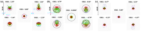
Figure 9.
Spot diagrams of the VIS channel at focal lengths of 69 mm (a), 207 mm (b), and 345 mm (c). Blue: wavelength of 0.486 μm; green: wavelength of 0.588 μm; red: wavelength of 0.656 μm.
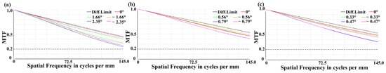
Figure 10.
MTF curves of the VIS channel at focal lengths of 69 mm (a), 207 mm (b), and 345 mm (c). The MTF value at the horizontal dashed line is 0.2.
Figure 11 shows the zoom curve of the VIS channel, where the x-axis represents the focal length and the y-axis represents the distances of the zoom group and the compensation group relative to the fixed front group. The results indicate that the zoom curve is smooth.
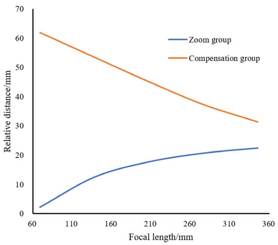
Figure 11.
Zoom curve of the VIS channel.
3.3. SWIR Channel Design
The SWIR channel adopts the same design approach as the VIS channel. The detector has a resolution of 640 × 512 and a pixel size of 15 μm. Table 4 lists the zoom parameters of the optical path and Figure 12 shows the optical path with a focal length of 100–500 mm, an FOV of 1.44–7.08° and a total length of 530.4 mm, including 12 lenses in total. The fixed front group and the zoom group, mainly responsible for optical power and zoom, use combinations of single lens and double-cemented lenses. The compensation group and the fixed post group adopt triple-element separated lens groups with more variables to compensate for aberrations of the front groups. Figure 13 shows the SWIR channel after the optical path is connected in series with the common-aperture optical path, with a focal length of 300–1500 mm and an FOV of 0.48–2.36°.
Table 4.
Zoom parameters of the SWIR relay optical path (unit: mm).
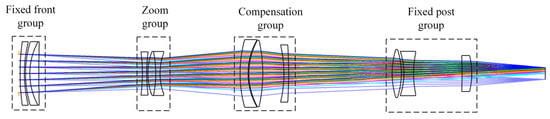
Figure 12.
Optical path of the 5× SWIR relay system.
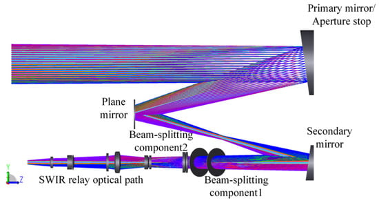
Figure 13.
Optical path of the SWIR channel.
In Figure 13, SWIR rays emerge from the common-aperture optical path and then pass through the beam-splitting components to form an image on the detector. The spot diagrams of the SWIR channel are presented in Figure 14. The RMS of spots ranges from 3.767 to 7.657 μm, which is smaller than the detector’s pixel size, providing reliable assurance for the imaging. Figure 15 shows the MTF curves of the channel at a cutoff frequency of 33 lp/mm. The results indicate that the MTF curves of the central FOV are nearly close to the diffraction limit, and the MTF values of the edge FOV are all above 0.2, confirming that the channel possesses excellent imaging performance.
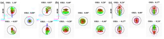
Figure 14.
Spot diagrams of the SWIR channel at focal lengths of 300 mm (a), 900 mm (b), and 1500 mm (c). Blue: wavelength of 0.9 μm; green: wavelength of 1.3 μm; red: wavelength of 1.7 μm.
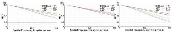
Figure 15.
MTF curves of the SWIR channel at focal lengths of 300 mm (a), 900 mm (b), and 1500 mm (c). The MTF value at the horizontal dashed line is 0.2.
Figure 16 shows the zoom curve of the SWIR channel, where the x-axis represents the focal length and the y-axis represents the distances of the zoom group and the compensation group relative to the fixed front group. The results indicate that the zoom curve is smooth.
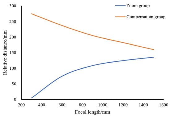
Figure 16.
Zoom curve of the SWIR channel.
3.4. MWIR Channel Design
The MWIR channel adheres to the same design concept as the VIS channel. However, unlike VIS and SWIR imaging, MWIR imaging is categorized as thermal radiation imaging. To reduce stray radiation, a cooled MWIR camera is used, with the cold stop matched to the exit pupil of the optical system. The camera has a resolution of 640 × 512 and a pixel size of 15 μm. Table 5 presents the zoom parameters. Figure 17 shows the optical path with a focal length of 100–200 mm, an FOV of 3.54–7.08° and a total length of 225.0 mm, including seven lenses and a detection window. The optical path adopts a two-stage imaging structure with an intermediate image plane to reduce the aperture of the front lens group. Due to the significant difference in the thermal expansion coefficients between MWIR materials and adhesives, all four components utilize separated lens groups. Compared with VIS materials, MWIR materials are more expensive. To reduce the number of lenses, aspheric surfaces are used to reduce aberrations. Figure 18 illustrates the MWIR channel formed by cascading the optical path with the common-aperture optical path, featuring a focal length of 300–600 mm and an FOV of 1.18–2.36°.
Table 5.
Zoom parameters of the MWIR relay optical path (Unit: mm).
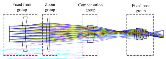
Figure 17.
Optical path of the 2× MWIR relay system.
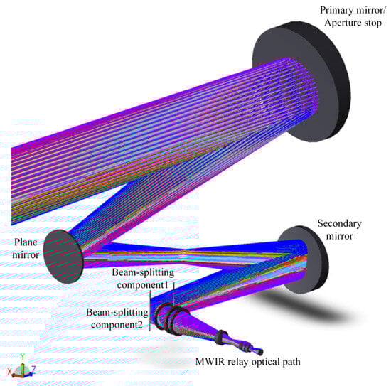
Figure 18.
Optical path of the MWIR channel.
In Figure 18, MWIR rays emerge from the common-aperture optical path, pass through component 1, are reflected by component 2 into the relay optical path, and finally form an image on the detector. The spot diagrams of the MWIR channel are presented in Figure 19. The RMS across different FOVs at various focal lengths ranges from 4.638 to 14.983 μm, which is smaller than the detector’s pixel size, providing reliable assurance for the imaging. Figure 20 shows the MTF curves of the channel at different focal lengths, with a cutoff frequency of 33 lp/mm. The results indicate that the MTF values are above 0.2, confirming that the system possesses excellent imaging performance.
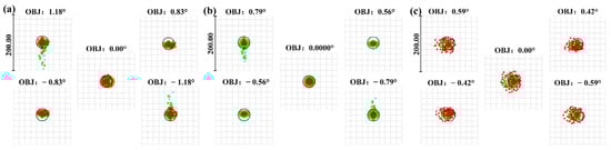
Figure 19.
Spot diagrams of the MWIR channel at focal lengths of 300 mm (a), 450 mm (b), and 600 mm (c). Blue: wavelength of 3.7 μm; green: wavelength of 4.2 μm; red: wavelength of 4.8 μm.
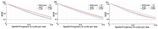
Figure 20.
MTF curves of the MWIR channel at focal lengths of 300 mm (a), 450 mm (b), and 600 mm (c). The MTF value at the horizontal dashed line is 0.2.
Figure 21 shows the zoom curve of the MWIR channel, where the x-axis represents the focal length, the y-axis represents the distances of the zoom group, and the compensation group relative to the front fixed group. The results indicate that the zoom curve is smooth.
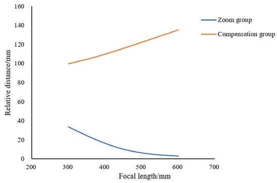
Figure 21.
Zoom curve of the MWIR channel.
The MWIR channel requires a narcissus analysis because of the adoption of the cooled camera. The narcissus analysis is conducted by calculating the YNI (the product of the paraxial marginal ray height Y on the optical surface, the refractive index N of the incident medium, and the incident angle I) and combining with the reverse ray tracing method. Since narcissus is primarily caused by the relay optical path, the analysis focuses on the part. Table 6 lists the YNI of each surface.
Table 6.
of each surface in the MWIR relay optical path.
When the absolute value of YNI is less than 1, the surface contributes significantly to narcissus and may affect the imaging; otherwise, the contribution is negligible [21]. As shown in Table 6, the absolute YNI of S15 and S16 are below 1. Therefore, reverse ray tracing was performed on S15 and S16, as illustrated in Figure 22 and Figure 23. The reverse-traced rays exhibit a divergent trend and do not converge on the image plane, resulting in minimal impact on the image quality. Overall, the intensity of the narcissus is not high and can be ignored.
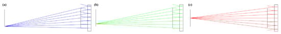
Figure 22.
Reverse ray tracing of S15 in the MWIR relay optical path at 1FOV (a), 0.707 FOV (b) and 0 FOV (c).
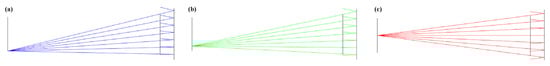
Figure 23.
Reverse ray tracing of S16 in the MWIR relay optical path at 1FOV (a), 0.707 FOV (b) and 0 FOV (c).
Figure 24 shows the optical path of the integrated system, which combines the optical paths of the five modules into a single system. The system can, in real time, acquire the image information of the target across VIS, SWIR, and MWIR bands with different FOVs.
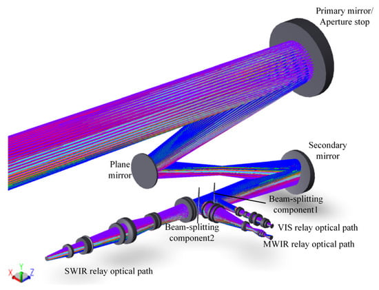
Figure 24.
Optical path of the three-channel common-aperture system.
4. Tolerance Analysis
The system adopts a modular design to enable independent assembly and adjustment of each spectral channel. The scheme allows operators to quickly locate the adjustment position of the target channel and effectively addresses the mutual interference in the assembly and adjustment of the different channels. Modular design can also significantly improve the efficiency of tolerance analysis. As a key step to evaluate the feasibility of optical design [22], traditional multi-channel common-aperture systems adopt an integrated analysis mode, which suffers from low efficiency due to the complex structure and large number of components. Based on the modular layout, designers can first conduct tolerance analysis for individual modules and then proceed to the channel analysis. During the analysis phase of each channel, sensitivity analysis is carried out with the co-aperture optical path as the reference, which greatly enhances the efficiency of tolerance analysis.
The RMS of the wavefront is adopted as the evaluation criterion for tolerance analysis of the afocal common-aperture optical path [23]. According to the current manufacturing capability, its tolerances are listed in Table 7. For the relay optical path, the MTF is the typical evaluation criterion for tolerance analysis [24]. Since the sensitivity of an optical path to minor deviations is inversely proportional to the wavelength, tolerance analysis is performed in the order of MWIR, SWIR, and VIS. The tightened tolerances from the preceding optical path are directly adopted in the subsequent analysis, as shown in Table 8.
Table 7.
Tolerances for the common-aperture optical path.
Table 8.
Tolerances for the relay optical paths.
For the full-FOV common-aperture optical path, the probability that the RMS of the wavefront is less than 0.063λ is 90%, which meets the criterion of the RMS < 1/14λ [17,18]. To be resolvable by photosensitive devices such as CCD and CMOS, the MTF of the relay optical paths must exceed 0.1 at the cutoff frequency [25]. For the MWIR relay optical path with different focal lengths, the probability of full-FOV average MTF exceeding 0.15 at 33 lp/mm is 90%; for the SWIR, the probability is 90% for the MTF over 0.20 at 33 lp/mm; for the VIS, 90% for full-field average MTF over 0.20 at 145 lp/mm. The analysis results demonstrate that each module is feasible. In the integrated analysis, sensitivity analysis is conducted on the distance, decentration, and tilt between them, and the tolerance specifications are listed in Table 9.
Table 9.
Tolerances for the optical channels.
For the MWIR channel, there is a 90% probability that the reduction in full-field average MTF at 33 lp/mm is less than 0.00032, the value is 0.00029 for the SWIR channel, and the value is 0.00042 for the VIS channel. The analysis shows that the deviations introduced during integration exert a negligible impact on system imaging, verifying the advantage of the modular layout scheme.
5. Discussion
The multi-channel common-aperture optical system enables independent and synchronous multi-band imaging. In addition, the modular layout proposed in the paper reduces the difficulty of assembly of such optical systems. However, the scheme has certain limitations. Although the off-axis design ensures 100% light passing, it introduces additional wavefront distortion to the system, and the phenomenon becomes prominent after integration with relay optical paths. The wavefront diagrams of each channel at different focal lengths are presented in Figure 25, Figure 26 and Figure 27. The maximum PV of the wavefront in the VIS channel is 0.226λ; for the SWIR, the maximum PV reaches 0.347λ; for the MWIR, the maximum PV reaches 0.294λ. The wavefront PV values of each channel are close to λ/4 [17,18], far from the requirements of high-precision detection fields such as aerospace and medicine. For conventional target detection corresponding to the design requirements in the article, the wavefront aberration induced is negligible. However, with the improvement in detection accuracy, the accurate compensation is crucial for applications in astronomy, medicine and other fields [26].
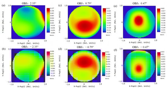
Figure 25.
Wavefront distribution of the VIS channel at focal length 69 mm, 1 FOV (a); 69 mm, −1 FOV (b); 207 mm, 1 FOV (c); 207 mm, −1 FOV (d); 345 mm, 1 FOV (e); 345 mm, −1 FOV (f).
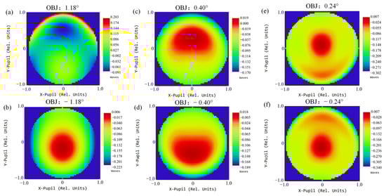
Figure 26.
Wavefront distribution of the SWIR channel at focal length 300 mm, 1 FOV (a); 300 mm, −1 FOV (b); 900 mm, 1 FOV (c); 900 mm, −1 FOV (d); 1500 mm, 1 FOV (e); 1500 mm, −1 FOV (f).
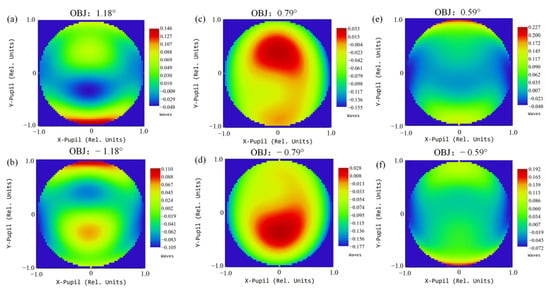
Figure 27.
Wavefront distribution of the MWIR channel at focal length 300 mm, 1 FOV (a); 300 mm, −1 FOV (b); 450 mm, 1 FOV (c); 450 mm, −1 FOV (d); 600 mm, 1 FOV (e); 600 mm, −1 FOV (f).
With the advancement of optical manufacturing and testing technologies [27], freeform surface lenses with non-rotational symmetry can rectify asymmetric wavefront distortions [28]. For correction of wavefront aberrations, the optical system needs to be optimized as an integrated entity. However, when relay optical paths achieve satisfactory imaging quality, the compensation lens with a freeform surface can be simplified to a single piece, avoiding an increase in the difficulty of assembly [29]. The introduction of freeform surfaces expand the application scope of modular design schemes for off-axis multi-channel common-aperture optical systems [30].
6. Conclusions
The paper proposes a modular design method, based on which a common-aperture optical system with three channels (VIS, SWIR, and MWIR) is designed and subjected to tolerance analysis. The system can detect 4 m × 4 m targets at 20 km and recognize the targets at 10 km. The modular layout supports the separate design and assembly of each optical path before integration. The common-aperture optical path uses an off-axis reflective beam-shrinking design, reducing the light obstruction ratio to 0%, minimizing the aperture size and weight of the refractive optical path, and extending the focal length of them. The relay optical path of each spectral band realizes smooth switching between detection and recognition through continuous zooming. Compared with the design of existing coaxial systems, the method ensures 100% light input for each spectral channel and reduces overall assembly difficulty, which is of great significance to the development of complex optical systems compatible with more optical channels.
The method exhibits a certain limitation in fields requiring high-precision detection, such as astronomy and medicine. The off-axis design introduces more asymmetric wavefront distortions, which is detrimental to the improvement in system performance. To address the limitation, existing studies have utilized the asymmetric surface characteristics of freeform surfaces to compensate for wavefront distortions. The measure not only significantly expands the engineering application of modular design for multi-channel optical systems but also marks the entry of the optical design field into a new stage of innovative development.
7. Patents
This work has been used to apply for a patent.
Author Contributions
Conceptualization, Y.W. and L.W.; methodology, Y.W., L.W. and F.W.; software, Y.W. and Q.W.; validation, Y.W. and J.L.; formal analysis, Y.W.; investigation, Y.W., B.Y. and X.R.; resources, Y.W. and B.Y.; data curation, Y.W.; writing—original draft preparation, Y.W.; writing—review and editing, L.W., F.W. and Q.W.; project administration, F.W. All authors have read and agreed to the published version of the manuscript.
Funding
This work is supported in part by Scientific Research Program of Education Department of Shaanxi Province (24JK0484), Natural Science Basic Research Program of Shaanxi Province (2025JC-YBQN-109), and Postdoctoral Research Project of Shaanxi Province (2024BSHSDZZ150).
Data Availability Statement
The data are unavailable due to privacy.
Acknowledgments
We thank Ruan Xiaoxia for her valuable discussions and assistance in optical design.
Conflicts of Interest
Author Baoyi Yue was employed by the company Xi’an Guide Technology Co., Ltd. The remaining authors declare that the research was conducted in the absence of any commercial or financial relationships that could be construed as a potential conflict of interest.
References
- Liu, Q.X.; Chen, H.Y.; Zhao, F. Maritime target detection algorithm based on fusion of visible and infrared images. J. Supercomput. 2024, 81, 22. [Google Scholar] [CrossRef]
- Hossein, T.S.; Sepideh, S. Assessing the risk of hospital information system implementation using IVIF FMEA approach. Int. J. Healthc. Manag. 2020, 14, 676–689. [Google Scholar]
- Xu, Z.H.; Yuan, X.Y.; Zhou, T.K.; Fang, L. A multichannel optical computing architecture for advanced machine vision. Light Sci. Appl. 2022, 11, 255. [Google Scholar] [CrossRef] [PubMed]
- Yang, K.X.; Xiang, W.; Chen, Z.S.; Zhang, J.; Liu, Y. A review on infrared and visible image fusion algorithms based on neural networks. J. Vis. Commun. Image Represent. 2024, 101, 104179. [Google Scholar] [CrossRef]
- He, F. Remote sensing of planetary space environment. Chin. Sci. Bull. 2020, 65, 1305–1319. [Google Scholar] [CrossRef]
- Yan, A.Q.; Chen, W.N.; Li, Q.X.; Guo, M.; Wang, H. Optical design of a visible/short-wave infrared common-aperture optical system with a long focal length and a wide field-of-view. Appl. Opt. 2024, 63, 2382–2391. [Google Scholar] [CrossRef]
- Ying, Y.M.; Yang, B.; Wang, Q.J. Design of the dual-band common-aperture optical imaging system. Results Opt. 2025, 12, 100863. [Google Scholar] [CrossRef]
- Chen, Y.; Gao, M.; Song, X. Method to design the common aperture multi-band optical system based on the PSO algorithm. Opt. Express 2021, 29, 18325–18335. [Google Scholar] [CrossRef]
- Yue, W.; Jin, G.; Yang, X.B. Adaptive Particle Swarm Optimization for Automatic Design of Common Aperture Optical System. Photonics 2022, 9, 807. [Google Scholar] [CrossRef]
- Zhang, K.L.; Pan, Y.; Xu, X.P.; Xu, L.; Liu, W.; Hu, M.; Lu, Y.; Cao, Y. Opto-mechanical-thermal integration design of the primary optical system for a tri-band aviation camera. Measurement 2025, 242, 116319. [Google Scholar] [CrossRef]
- Zhang, L.; Zhang, Z.H.; Zhu, J.Q.; Wang, X.; Lin, G.; Li, B.; Wang, X. Design of a three-channel common-aperture miniaturized optical system based on the Ritchey-Chretien (RC) telescope. Opt. Lasers Eng. 2025, 193, 109075. [Google Scholar] [CrossRef]
- Yu, J.D.; Mao, X.L. Design of Off-axis four-mirror optical systems enabled by freeform optics. Photonics 2025, 12, 107. [Google Scholar] [CrossRef]
- Nie, Y.; Mohedano, R.; Benítez, P.; Chaves, J.; Miñano, J.C.; Thienpont, H.; Duerr, F. Optical design of an ultrashort throw ratio projector with two freeform mirrors. In Proceedings of the SPIE Optical Engineering + Applications, San Diego, CA, USA, 28 September 2016. [Google Scholar]
- Hu, B.; Ji, Y.; Liu, J.F.; Li, Y.; Jin, L.; Tang, T. Design of off-axis mirror system for ultra-long exit pupil distance space laser communication terminal. In Proceedings of the AOPC 2022: Novel Optical Design and Optics Ultra Precision Manufacturing and Testing, Beijing, China, 20 January 2023; Institute of Space Mechanics and Electricity: Beijing, China, 2023. [Google Scholar]
- Niu, Y.F.; Zhong, Z.W.; Zhang, D.B.; Xi, Y.; Liang, J. A Method of Visual Sensor Employment Planning for UAV Target Detection. In Proceedings of the 28th Chinese Control and Decision Conference, Yinchuan, China, 28 May 2016. [Google Scholar]
- Artiukhina, K.N.; Perosa, A.L.; Zambrano, L. Afocal systems formed by mirror off-axis paraboloid. Sci. Tech. 2017, 16, 407–414. [Google Scholar] [CrossRef]
- Doyle, K.B.; Genberg, V.L.; Michels, G.J. Integrated Optomechanical Analysis; SPIE Press: Bellingham, WA, USA, 2002; pp. 35–62. [Google Scholar]
- Meng, Q.Y.; Qi, Y.S.; Chen, Q. Review of reflective/catadioptric zoom optical systems. Opt. Precis. Eng. 2025, 33, 2718–2733. [Google Scholar]
- Li, H.; Chen, H.H.; Li, X.X.; Song, H.; Wang, D. Structural optical design of multi-group, high zoom ratio optical systems. Opt. Commun. 2024, 551, 130022. [Google Scholar] [CrossRef]
- Hao, Q.; Chen, X.M.; Du, K. Four-group stabilized zoom lens design of two focal-length-variable elements. Opt. Express 2013, 21, 7758–7767. [Google Scholar] [CrossRef]
- Bu, H.Y.; Yu, L.Y.; Tian, H.N.; Wang, J. Narcissus suppression of medium-wave infrared imaging system. Chin. Opt. 2023, 16, 1414–1423. [Google Scholar] [CrossRef]
- Zhang, K.Y.; Dai, F.J.; Li, Z.Y. Homogeneous optimization approach for reducing sensitivity of an optical lens system. Opt. Eng. 2020, 59, 035109. [Google Scholar] [CrossRef]
- Yan, J.H.; Hu, Z.J.; Zhu, D.Y. Design of compact off-axis three-mirror afocal system based on freeform surface. Acta Photonica Sin. 2022, 51, 297–307. [Google Scholar]
- Xing, Y.; Yu, J.; Wang, X.; Li, H.; He, C.; Ma, Z.; Wang, D.; Wang, Z.; Cheng, X.; Dun, X. Comprehensive performance domain tolerance analysis methodology for freeform imaging spectrometers. Opt. Express 2024, 32, 14405–14419. [Google Scholar] [CrossRef]
- Yu, D.; Tan, H. Optical Engineering, 4th ed.; China Machine Press: Beijing, China, 2016; pp. 220–221. [Google Scholar]
- Khorin, P.; Dzyuba, A.; Khonina, S. Optical wavefront aberration: Detection, recognition, and compensation techniques—A comprehensive review. Opt. Laser Technol. 2025, 191, 113342. [Google Scholar] [CrossRef]
- Gong, L.Q.; Fan, C.; Shen, Z.; Chen, Z.; Zhang, L. Research on discretization algorithm of free-form surface for robotic polishing. J. Manuf. Process. 2023, 92, 350–370. [Google Scholar] [CrossRef]
- Fang, F.Z.; Cheng, Y.; Zhang, X.D. Design of freeform optics. Adv. Opt. Technol 2013, 2, 445–453. [Google Scholar] [CrossRef]
- Yu, J.; Xiang, L.M. Correction of Wavefront Distortion in Common Aperture Optical Systems Based on Freeform Lens. Photonics 2025, 12, 103. [Google Scholar] [CrossRef]
- Thompson, K.P.; Rolland, J.P. Freeform optical surfaces: A revolution in imaging optical design. Opt. Photonics News 2012, 23, 30–35. [Google Scholar] [CrossRef]


Disclaimer/Publisher’s Note: The statements, opinions and data contained in all publications are solely those of the individual author(s) and contributor(s) and not of MDPI and/or the editor(s). MDPI and/or the editor(s) disclaim responsibility for any injury to people or property resulting from any ideas, methods, instructions or products referred to in the content. |
© 2026 by the authors. Licensee MDPI, Basel, Switzerland. This article is an open access article distributed under the terms and conditions of the Creative Commons Attribution (CC BY) license.