1. Introduction
The Global Navigation Satellite System (GNSS) has been widely applied in many fields and has become an essential infrastructure for societal development. The four major GNSSs all employ constellations primarily composed of Medium-Earth Orbit (MEO) satellites. The MEO satellites of the global positioning system (GPS) are unevenly distributed across six orbital planes, whereas the MEO satellites of Russia’s Global Navigation Satellite System (GLONASS), the European Union’s Galileo, and China’s BeiDou Navigation Satellite System (BDS) form Walker constellations, which are distributed across three orbital planes [
1]. The GNSS orbits are primarily tracked by ground stations, which usually need to be evenly distributed throughout the globe to ensure a suitable observation geometry. However, because of limitations in the number and distribution of ground stations, not all GNSS satellites can be tracked at a sufficiently high accuracy. Currently, the 1D accuracy of GPS and GLONASS orbits, based on ground station observations provided by the International GNSS Service (IGS), is better than 3 cm [
2]. In contrast, the orbital accuracy of the BDS is lower because of its relatively small number of unevenly distributed ground stations [
3].
Inter-satellite ranging can enhance the orbital accuracy of navigation satellites by combining the orbital data obtained from ground stations. This capability also enables GNSSs to navigate autonomously without requiring the support of ground stations, thereby improving their survivability in extreme conditions. In 2011, Fernández [
4] described a GNSS exploratory project conducted by the European Space Agency (ESA), which analyzed the effects of introducing inter-satellite microwave ranging and communication links to improve GNSS and signal propagation performance. The results indicated that inter-satellite links (ISLs) are able to more effectively maintain the accuracy of satellite orbits and clocks. In practical applications, from the early 1990s, GPS satellites of the IIR series were already equipped with cross-link capabilities as part of the so-called Autonomous Navigation (AUTONAV) mode [
5]. The GPS IIR satellites determined inter-satellite distances using a time-division, dual-frequency two-way mode of the ultra-high frequency (UHF) band [
6]. However, the UHF band was prone to significant multipath errors and noise [
7]. Therefore, subsequent GPS ISLs used the Ka-band [
8]. The second generation of GLONASS satellites, GLONASS-M, employed inter-satellite microwave links to measure distances and to improve ephemeris and clock accuracy [
1]. The BDS also primarily used Ka-band ISLs to autonomously determine satellite orbits and synchronize inter-satellite times, achieving inter-satellite ranging errors of less than 0.25 ns [
9].
Compared to microwaves, optical waves have shorter wavelengths, superior directionality, higher signal-to-noise ratio gain, and greater modulation bandwidth. Therefore, laser ranging has a very high potential for ISLs as a high-precision ranging method, and it has been used to achieve favorable results in fiber-based time–frequency synchronization and satellite orbit determination [
10,
11,
12,
13]. Inter-satellite ranging carriers are also beginning to shift from microwaves to optical waves to enhance clock synchronization and ranging capabilities between satellites. In 2013, Pasynkov et al. reported on a verification experiment for laser communication ranging technology conducted between the GLONASS-728 and GLONASS-747 satellites, which achieved an inter-satellite ranging precision of 3 cm [
14]. Furthermore, the next-generation satellite GLONASS-K2 incorporated laser ISLs to further enhance the accuracy of its orbit determination and clock synchronization [
1,
15]. Michalak et al. introduced the Kepler navigation system proposed by the German Aerospace Center (DLR) [
16]. The space segment of this system was comprised of 24 Galileo-like MEO satellites and six Low-Earth Orbit (LEO) satellites equipped with ultra-stable optical clocks. These satellites were equipped with both microwave and laser payloads for inter-satellite ranging. In 2020, Yu et al. proposed a pseudo-code incoherent laser ranging scheme based on a regenerative synchronization mechanism for inter-satellite ranging scenarios involving relatively stationary satellites [
17]. This scheme was validated in laboratory tests. The slave station utilized a delay-locked loop to track and regenerate the pseudo-random code from the master station. The master station determined the distance information by calculating the phase difference between the received pseudo-random code and the transmitted pseudo-random code. The compensated ranging error was
mm, which was affected by the receiver clock error generated by the code tracking loop and the clock error produced by the clock source. In 2021, Zhu et al. designed an integrated solution for inter-satellite communication and ranging, successfully conducting on-orbit verification experiments with two satellites (BEIDOU-3 M21 and BEIDOU-3 M22) in the same circular orbit [
18]. The ranging scheme consisted of both coarse and fine distance measurements. Coarse ranging was achieved using the header of integer frames within, per second. The synchronization of symbols and data clock recovery was then implemented in hardware using code tracking loops. Finally, the fine phase (fine range) between the transmission clock and data reception clock was determined by constructing a reference clock, ultimately achieving a ranging precision of 2.6 mm. Yu et al. proposed an inter-satellite ranging scheme based on pseudo-random code amplitude modulation, in which the coarse distance measurement was performed using the cross-correlation method [
19]. New early and late codes were constructed by cyclically shifting the punctual code according to the coarse measurement. The fine distance was then determined using the early–late discriminator model with theoretical characteristic parameters. A ranging precision of 0.33 mm was achieved using fiber optics. However, within a distance of 150 mm (corresponding to a time delay of 500 ps), the ranging deviation was 6 mm (corresponding to a time delay deviation of 20 ps). As the measurement range increased, particularly when the time delay exceeded the width of one chip, the ranging deviation also increased. Ranging deviation can significantly affect the application of inter-satellite laser ranging to satellite orbit determination. Although orbit determination requires multiple measurements, the deviation of each measurement cannot be directly eliminated in the orbit determination software, preventing the high-precision characteristics of laser ranging from being effectively utilized.
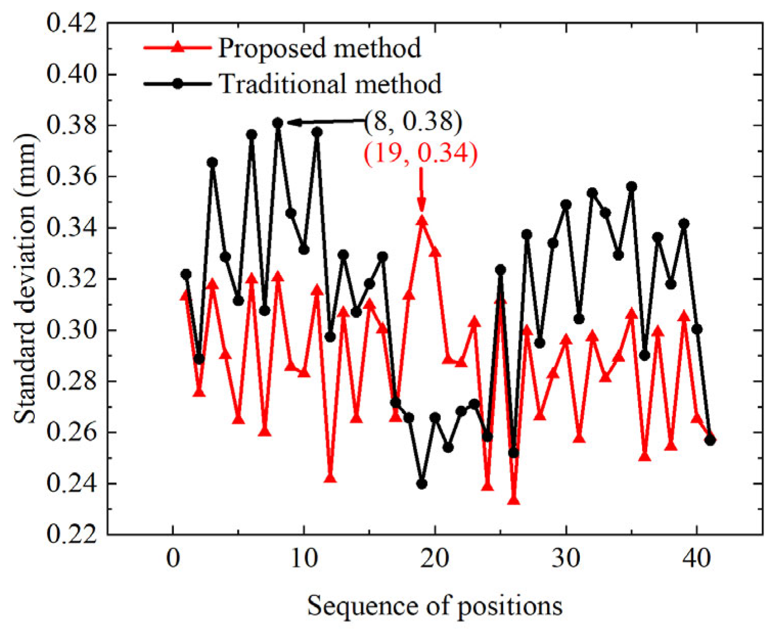
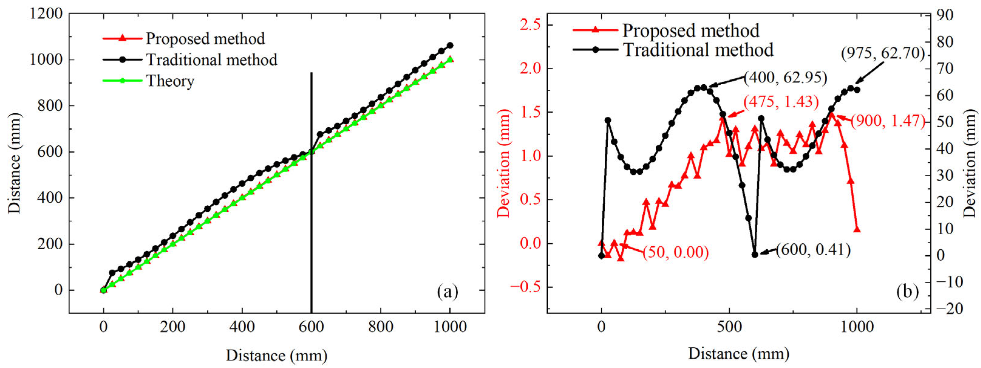
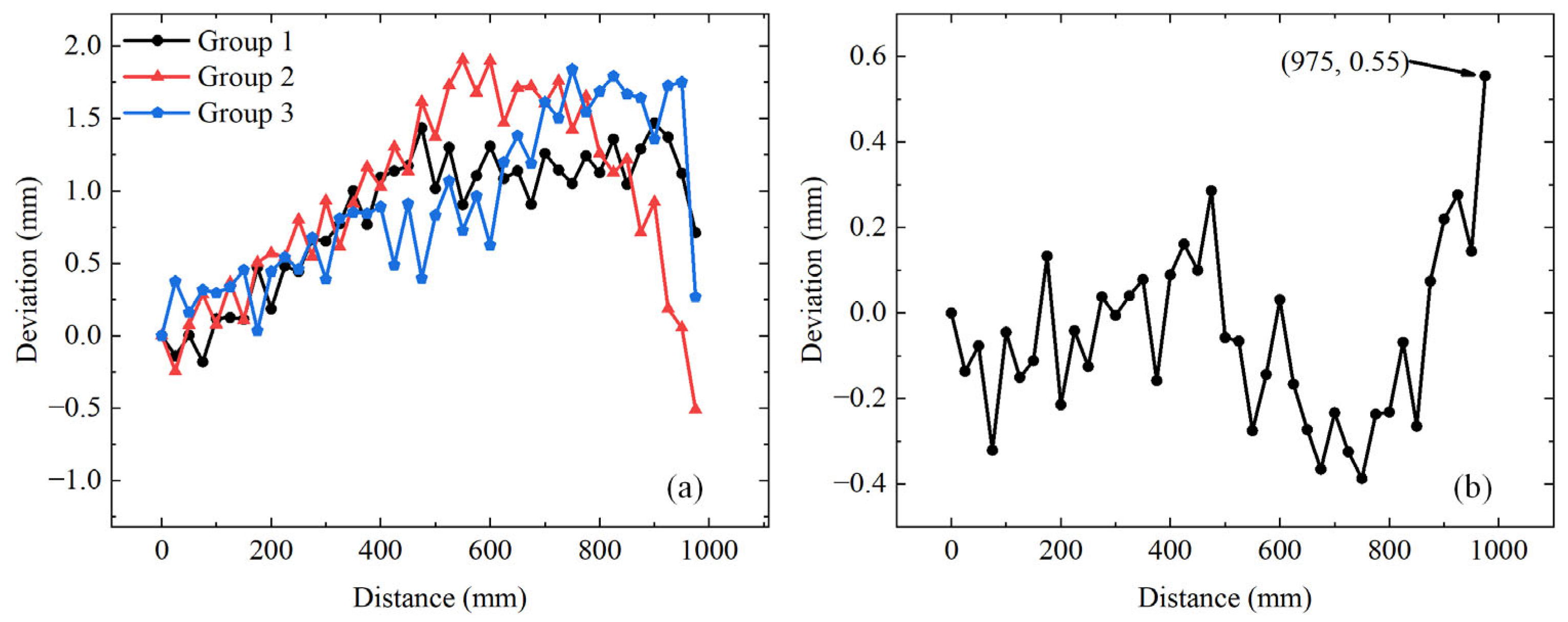
To achieve high-accuracy ranging and reduce inter-satellite laser ranging deviations, this study proposes a pseudo-random code phase-shift coherent laser ranging phase discrimination method that employs data shifting and a discriminator with calibrated characteristic parameters, which solves the problem of mutual restriction between ranging accuracy and ranging precision in the traditional method. In contrast to the traditional method, the proposed method shifts the data according to the position determined by the punctual code correlation peak. The shifted data are then cross-correlated and normalized with fixed early and late codes to accurately determine the fine distances. Additionally, a suite of varying distances is utilized in conjunction with a real-ranging system to calibrate the characteristic parameters of the phase discrimination model. A comparison between this method and the traditional method revealed that after calibration, the characteristic parameters of the phase discrimination model for the actual system differed from the theoretical values. For static target ranging, the ranging precisions of the proposed and traditional methods were 0.34 mm and 0.38 mm, respectively, and their ranging accuracies were 0.56 mm and 51.05 mm, respectively. The proposed method improved the ranging accuracy by a factor of 91. For dynamic targets, the ranging accuracies of the proposed and traditional methods were 0.13 mm and 0.20 mm, respectively, and their maximum ranging deviations were −0.38 mm and −1.26 mm, respectively. Furthermore, as the target distance increased, the distance deviation of the traditional method reached a maximum value before gradually decreasing, exhibiting periodicity, with a period equal to one code width. For speed measurements, the proposed method achieved an accuracy of 0.58 mm/s and a precision of 0.44 mm/s.
2. Principle
A schematic of the coherent ranging system, which is phase-modulated by a pseudo-random binary code, is illustrated in
Figure 1a. Fiber optic coupler 1 (FOC1) divides the laser into two parts: the signal
and the local oscillator
. The signal
is phase-modulated with the pseudo-random code
using an electro-optic phase modulator (EOPM). An acousto-optic modulator (AOM) is used to shift the frequency of the signal by a specified amount
. Finally, the frequency-shifted signal
is transmitted through a variable optical attenuator (VOA) and a collimator. The backscattered signal
from the target and local oscillator
are optically mixed using a 2 × 2 fiber optic coupler 2 (FOC2), leading the coherent light to a balanced detector, where it is converted into an electrical signal
of intermediate frequency (IF). The pseudo-random code
is generated by an arbitrary waveform generator (AWG), which produces a pseudo-random code synchronization pulse (PCSP) at the beginning of each pseudo-random code sequence to be fed into the acquisition module. The acquisition module is a digital storage oscilloscope (DSO), which samples the IF electrical signal triggered by the PCSP. Subsequently, the sampled data are processed on a computer to determine the distance and velocity of the target. The reference output clock (REF-Clock) of the DSO serves as the reference clock for the AWG to ensure that the transmission and reception of the system are synchronized.
The two output signals of FOC1 with a splitting ratio of
are expressed as [
20]
where
,
, and
denote the frequency, amplitude, and initial phase of the laser, respectively.
Here,
is a pseudo-random code composed of −1 and +1,
is the gate function,
denotes the chip duration,
denotes the length of the pseudo-random code,
, and
represents the impulse response of the low-pass filter (LPF).
The signal
is expressed as
where
is the phase modulation depth factor, and
is the frequency shift caused by the AOM. The expression for the backscattered light
from the target is
where
is the Doppler shift generated by the target velocity,
is the time delay of light to and from the target, and
is the amplitude attenuation coefficient. The backscattered light
is mixed with the local oscillation light
by FOC2 with a splitting ratio of
. The output voltage
of the balanced detector is expressed as
where
,
is the transimpedance of the balanced detector,
is the dielectric constant,
is the speed of light,
is the refractive index of the medium,
represents the responsivity of the photodiode,
represents the effective optical receiving area of the photodiode [
20],
, the sampling frequency of the analog-to-digital converter (ADC) is
(
, where
is the sampling period), and
is the noise. The variable
is discretely sampled via
and
is digitally demodulated, resulting in baseband data expressed as
where
represents the impulse response of the low-pass filter.
For ease of reading, the symbols involved in Equations (1)–(8) are summarized in
Table A1 in
Appendix A. Additionally, the symbols involved in the traditional and proposed methods are summarized in
Table A2 in
Appendix A.
The traditional ranging flow [
19,
21,
22] is illustrated in
Figure 1b. A segment of data, denoted as
, with a length of
, is extracted from the baseband data
and subsequently cross-correlated with the punctual code
. The length of
is
. The coarse distance
is determined according to the position
of the chip where the correlation peak is located, where
represents the speed of light. A new pseudo-random code
is generated by cyclically shifting the original pseudo-random code
according to
. New early
and late
codes are derived from
. Next,
and
are cross-correlated with
to obtain
and
, which are then used to compute
. The fractional part of the chip, representing the fine time delay, is derived inversely as
according to the early–late discrimination model
(
,
) [
21]. The ultimate distance of the target is
. The early–late discrimination model used in the traditional method is a theoretical model in which the parameter
is a theoretical value that is relevant to the length of the pseudo-random code, and the parameter
is equal to 0. The correlation function of the pseudo-random code determines the early–late discriminant model [
21,
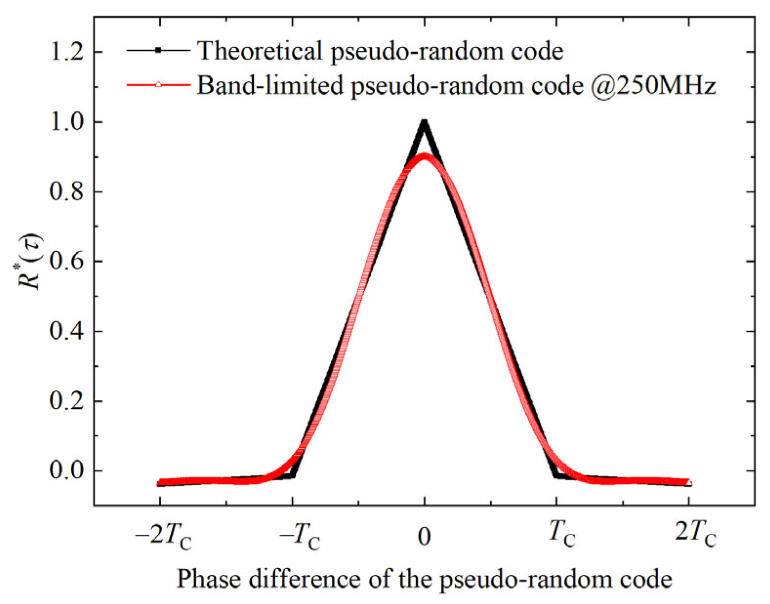
23]. The theoretical pseudo-random code has a rectangular waveform with an infinitely wide bandwidth. Its correlation function is [
23]
where
denotes the real part of the complex number
,
is the phase difference of the pseudo-random code,
is the spectral density of the pseudo-random code, and
is the signal power. When the bandwidth of the pseudo-random code is finite, its correlation function is [
23]
where
is the transfer function of the LPF.
Figure 2 shows the correlation functions of the theoretical pseudo-random code and the pseudo-random code with a bandwidth of 250 MHz. As shown in
Figure 2, the correlation function of the theoretical pseudo-random code is a triangle. The LPF changes the correlation function of the pseudo-random code, and the correlation function of the band-limited pseudorandom code is no longer a triangle. Therefore, the early–late discriminant models of pseudo-random codes with different bandwidths are also different. The actual ranging system is band-limited, and the devices used in the system are not ideal. When the theoretical phase discrimination model is applied to the actual ranging system, it can result in ranging deviations that decrease the accuracy of the ranging. Therefore, the characteristic parameters of the early–late discriminator model need to be calibrated to improve the ranging accuracy.
To solve this problem, this study calibrates the characteristic parameters of the phase detection model utilized in the real-world system. After this calibration, the fine time delay is calculated according to the calibrated parameters, thereby improving the accuracy of the distance measurements. The flow of the ranging process is illustrated in
Figure 1c. The data position
corresponding to the correlation peak is obtained via cross-correlation. The coarse distance is
. A segment of data
, with a length of
, is extracted along the time axis according to
. Then,
is correlated with
and
to obtain
. Finally, the fine distance
(
) is obtained via an inverse calculation using the phase discrimination model
that matches the actual system. The distance of the target is
. Because the characteristic parameters
and
in the phase discrimination model
are calibrated based on the actual system, the model matches the actual system. The proposed method can significantly improve the ranging accuracy.
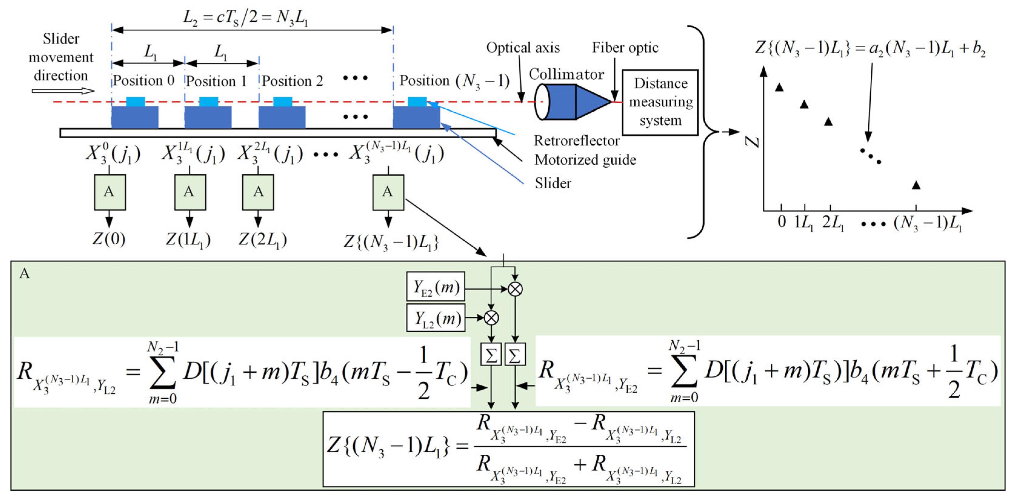
The proposed methodology initially employs this ranging system to establish a characteristic parameter calibration system with variable time delays. It calculates the value
for different time delays, where the actual time delay interval
is less than the ADC sampling period
. This principle is depicted at the top of
Figure 3. The position of the sampling point of the DSO in the chip is changed by adjusting the retroreflector position, which effectively changes the phase of the sampled data. Within the distance
corresponding to the sampling period, the retroreflector steps forward
each time for a total of
steps. The pseudo-random code synchronization pulse and the target echo are sampled simultaneously at each position, and
cycles of pseudo-random code are sampled. A pseudo-random sequence
of length
is extracted at each position from the target echo data
, where
is aligned with
. The mean value of
at each position is computed. By performing a least squares fitting on
sets of data
, one can derive the characteristic parameters
and
of the phase discrimination model
that matches the actual ranging system, as shown in the upper right area of
Figure 3. During the ranging process, the peak position
is obtained using the cross-correlation method, and the data
of length
are obtained according to
.
is obtained by performing the cross-correlation operation and normalization operation on
,
, and
according to
Figure 1c. The phase difference
is inversely calculated by taking
into the phase discrimination model
. The final distance of the target is
.
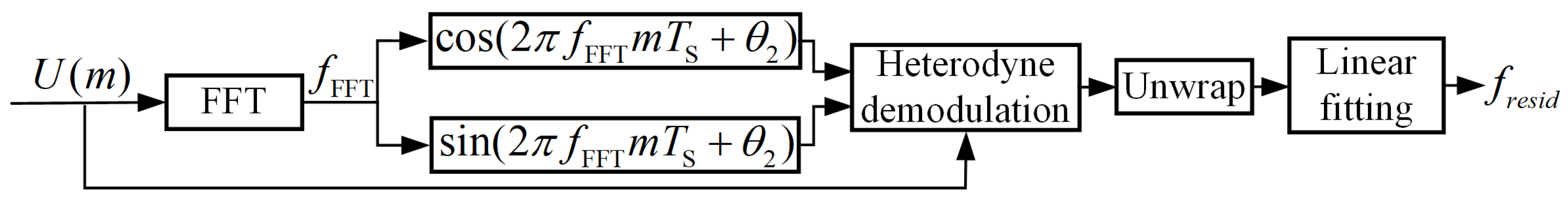
Figure 4 depicts the procedure for determining the velocity. Initially, a fast Fourier transform (FFT) operation is performed to obtain the frequency
. The local orthogonal digital waveforms
and
are then constructed according to
, where
is the initial phase. Next, heterodyne demodulation and phase unwrapping are conducted on
to derive the phase data
, along with the residual frequency difference
and the residual phase
. Subsequently, curve fitting is performed on the phase data to determine the residual frequency
. The speed of the target is expressed as
, where
represents the wavelength of the light wave.
In summary, it can be seen from Equations (9) and (10) and
Figure 2 that the correlation functions of the theoretical pseudo-random code and bandwidth-limited pseudo-random code are different. The correlation function determines the early–late discriminator model [
21,
23]. In the traditional method, an early–late discriminator model with theoretical characteristic parameters is used for ranging within the phase range of
or
by changing the local pseudo-random code. For the actual bandwidth-limited ranging system, this method cannot solve the problem of mutual constraints between ranging accuracy and ranging precision. Therefore, the situation of high ranging precision and poor ranging accuracy occurs [
19]. In this paper, the characteristic parameter calibration method and data-shifting method are adopted. An early–late discriminator model with calibrated characteristic parameters is used for ranging within the phase range of
. This method solves the problem of mutual restriction between ranging accuracy and ranging precision in the traditional method and achieves good ranging precision and ranging accuracy.
4. Discussion
The separation between neighboring satellites within the same orbital plane of a Walker constellation is approximately on the order of tens of thousands of kilometers, and the optical power received at the terminal is below 1
. We simulated the relationship between the ranging precision and received optical power, as well as the correlation between the received optical power and distance. For inter-satellite laser links, the optical power received at the terminal is [
24]
where
is the received power;
is the transmitted power;
is the transmitter gain;
(
is the diameter of the transmitting telescope, and
is the wavelength);
is the optical efficiency of the transmitter (the typical value of which is −1.74 dB);
is the path loss of the inter-satellite optical link;
(
is the inter-satellite distance);
is the link attenuation caused by the channel (which is equal to 1 for ISLs);
is the power loss caused by acquisition, pointing, and tracking (APT) misalignment, and its value of −0.56 dB is obtained according to the best matching relationship where the divergence angle of the communication beam is fives times the pointing error;
is the receiver gain (the aperture of the receiving telescope is the same as that of the transmitting telescope); and
is the optical efficiency of the receiver, which is the same as
here [
24].
The diameters of both the transmitting and receiving telescopes were fixed at 100 mm, the transmitted power was specified as 25 dB, and the link safety margin was set at 3 dB [
24,
25,
26]. For an inter-satellite distance of 21,343 km in the BDS, the received optical power was
.
The coherent receiver uses a local oscillator to improve the signal-to-noise ratio, in which case the noise is predominantly shot noise [
27]. Shot noise is modeled as a zero-mean random Gaussian process. In the shot noise limit, the SNR is expressed as [
28]
where
is the heterodyne efficiency,
is the responsivity,
is the received optical power,
is the electron charge, and
is the receiver bandwidth. A Monte Carlo simulation was conducted to analyze the relationship between the received optical power and the ranging precision. The results are depicted as black dots in
Figure 12. Additionally, the pink curve in
Figure 12 shows the correlation between the received optical power and the range.
Figure 12 illustrates that in the shot noise limit, the optical power decreased as the ranging precision increased with distance. The ranging precision deteriorated sharply at an optical power of 27 nW. Here, 27 nW of optical power corresponds to a distance of 8220 km, with a ranging error of 0.15 mm and a time delay error of 0.5 ps. When the received optical power was 3 nW, the corresponding distance was 24,663 km, with a ranging error of approximately 1.51 mm and a time-delay error of approximately 5.03 ps.
The theoretical waveform of the pseudo-random code is a rectangular wave, its spectrum is infinite wide, its main energy is concentrated in the main lobe, and its theoretical phase discrimination model Z is a linear model, as shown in
Figure 13. The bandwidth of the actual ranging system is limited, and the devices used in the system are not ideal. These factors lead to a poor matching between the theoretical phase discrimination model and the actual system. When the theoretical phase discrimination model is used in the actual system, it will bring errors.
Figure 14a simulates the relationship between the phase discrimination model and the bandwidth. When the bandwidth becomes small, the phase discrimination model moves away from the theoretical phase discrimination model, and when the bandwidth becomes large, the phase discrimination model approaches the theoretical model. When the system bandwidth is infinitely wide, the phase discrimination model is equal to the theoretical model. As shown in
Figure 14a, there is a difference between the phase discrimination model of the band-limited system and the theoretical model. When the theoretical model is applied to a system with limited bandwidth, it results in a decrease in the ranging accuracy.
Figure 14a also illustrates the theoretical relationship between the ranging accuracy and ranging range in the traditional method. The phase discrimination range of the pseudo-random code is
, corresponding to a chip width, which leads to the ranging accuracy periodically improving and deteriorating as the ranging range increases. When the system bandwidth is equal to one times the chip rate, the ranging accuracy of traditional method becomes very poor within the period, and as the system bandwidth continues to increase, the ranging accuracy of traditional method will gradually improve within the period.
Figure 14b simulates the relationship between ranging accuracy, bandwidth, and SNR. In Yu’s article, the SNR for ranging is greater than 21 dB [
19]. For comparison, we simulated the variations in ranging accuracy when the SNR is greater than 20 dB. The main energy of the pseudo-random code is concentrated within the main lobe. As the system bandwidth increases, the discrimination model approaches the theoretical discrimination model, improving the ranging accuracy. However, the SNR decreases, leading to a deterioration in the ranging precision, as shown in
Figure 14b. This issue is inherent in the traditional method, where the accuracy and precision of the distance measurement are mutually restrictive. This also explains the ranging precision of 0.33 mm and the ranging accuracy of 6 mm mentioned in Yu’s article. The method proposed in this paper reduces the system bandwidth, ensures a high SNR, and improves the ranging accuracy using a discriminator with calibrated characteristic parameters so that the ranging accuracy does not show periodic variations as the ranging range increases. By employing a data-shifting method, the consistency of the discriminator in ranging is maintained. Compared with the traditional method, the proposed method improves the ranging accuracy and ensures a high ranging precision, which solves the situation that the ranging accuracy and ranging precision constrain each other. This is the difference between the proposed method in this paper and the method in Yu’s paper.

