Abstract
The ATLAS lidar on NASA’s Earth-orbiting ICESat-2 satellite has operated continuously since its launch in September 2018, with no sign of degradation. Compared to previous international single-beam spaceborne lidars, which operated at a few tens of Hz, the single-photon-sensitive, six-beam ATLAS pushbroom lidar provides 60,000 surface measurements per second and has accumulated almost 3 trillion surface measurements during its six years of operation. It also features a 0.5 m2 telescope aperture and a single, 5 Watt, frequency-doubled Nd:YAG laser generating a 10 KHz train of 1.5-nanosecond pulses at a green wavelength of 532 nm. The current paper investigates how, with minor modifications to the ATLAS lidar, this capability might be extended to other planets within our solar system. Crucial to this capability is the need to minimize the solar background seen by the lidar while simultaneously providing, for long time intervals (multiple months), an uninterrupted, modestly powered, multimegabit per second interplanetary laser communications link to a terminal in Earth orbit. The proposed solution is a pair of Earth and planetary satellites in high, parallel, quasi-synchronized orbits perpendicular to their host planet’s orbital planes about the Sun. High orbits significantly reduce the time intervals over which the interplanetary communications link is blocked by their host planets. Initial establishment of the interplanetary communications link is simplified during two specific time intervals per orbit when the sunlit image of the two planets are not displaced from their actual positions (“zero point ahead angle”). In this instance, sunlit planetary images and the orbiting satellite laser beacon can be displayed on the same pixelated detector array, thereby accelerating the coalignment of the two communication terminals. Various tables in the text provide insight for each of the eight planets regarding the impact of solar distance on the worst-case Signal-to-Noise Ratio (SNR), the effect of satellite orbital height on the duration of the unblocked interplanetary communications link, and the resulting planetary surface continuity and resolution in both the along-track and cross-track directions. For planets beyond Saturn, the laser power and/or transmit/receive telescope apertures required to transmit multimegabit-per-second lidar data back to Earth are major challenges given current technology.
1. Introduction
Various spaceborne multiphoton lidars, typically operating at tens of pulses per second, have been successfully developed by NASA and other international space agencies and deployed for the purpose of mapping Earth, other planets and moons, and even certain asteroids. NASA’s contributions to date include the Geoscience Laser Altimeter System (GLAS) on the Earth-orbiting ICEsat-1 satellite, the Mars Orbiter Laser Altimeter (MOLA), the Mercury Laser Altimeter (MLA), and the Lunar Orbiter Laser Altimeter (LOLA). Missions to map Asteroids include the Near Laser Rangefinder, Osiris Rex, and the Japanese Hayabusa 1 and 2 missions. A recent review paper provides a summary of the goals and capabilities of spaceborne lidars to date [1].
Since the single-photon-sensitive ATLAS lidar on NASA’s ICESat-2 satellite was launched on 18 September 2018 into a 500 km high orbit, it has provided well over 2 trillion topographic measurements at a rate of 60,000 per second. ATLAS has achieved this result using three “strong” and three “weak” beams, all provided by a single laser producing a 5 Watt train of 1.5-nanosecond pulses at a 10 KHZ rate, with each pulse containing only 500 microjoules of energy. The pulse energies in the strong beams were four times (125 µJ) that of the “weak” beams (31 µJ). Furthermore, the passively Q-switched and frequency-doubled Nd:YAG laser, developed by NASA Goddard Space Flight Center and its contractors, operates at a green wavelength of 532 nm and, as of the time of writing, has, remarkably, shown no signs of degradation after almost 7 years in orbit.
The original single-photon lidar concept, put forward by the current author [2] for the mapping of planets and/or their moons, had suggested 16 weak beams, resulting in 160,000 measurements per second. However, certain ICESat-2 science goals (primarily related to cryosphere, biomass, and ocean studies somewhat unique to Earth) could not be met by the weak beams alone [3]. However, if one is contemplating tens (or even hundreds) of thousands of measurements per second at a distant planet, how does one collect, store, and transmit that data back to Earth?
2. Data Collection Rates
If we assume that the range data is being downloaded to Earth via On–Off Keying (OOK), i.e., via a series of ones and zeros, each measurement requires that we record and transmit the beam number (first 4 bits for 9 to 16 beamlets) followed by n bits yielding the measured range to the surface given by
where Rmax is the maximum range to the surface and δ is the desired range resolution. For the ATLAS altitude of 500 km and a range resolution of 10 cm, Equation (1) yields n = 20 for a total of 24 bits per measurement. We now multiply by the number of beams (16) and the laser fire rate (10 kHz) to obtain a nominal data download rate of 3.84 Megabits per second or 0.24 Megabits per second per beamlet Thus, in one Earth day, one beamlet would generate 20,736 Megabits or 20.736 Gigabits of data. Thus, in order to transfer such a large amount of data from the planet under study to Earth, the interplanetary communication system would need a roughly 4 Mbit/s capability with minimal interruptions in the data flow.
3. Gaussian Laser Beam Propagation and Optical Antennas
The lowest-order (and most useful) mode of a laser has a Gaussian shape. The smallest beam radius occurs at the “waist” and is typically on the order of a few millimeters and located within the laser resonator. As we move a large distance z from the waist, the beam radius grows according to the formula
where λ is the laser wavelength and z is the distance from the waist with radius . Thus, far from the laser, the beam area increases quadratically with distance and is given by
where A0 is the Gaussian beam area at z = 0. We note from the latter equation that the beam area far from the waist decreases with the square of the wavelength λ and also with increasing beam waist radius w0. This wavelength dependence is what gives laser communications an advantage over more conventional millimeter or microwave systems that require huge antennas to achieve high data rates over interplanetary distances.
One can increase the size of the laser beam waist through a modestly sized magnifying telescope, which, in turn, can reduce the divergence of the beam in the far field by several orders of magnitude [4]. For example, prior to the turn of the century, the mm accuracy satellite laser ranging systems transmitted a few mJ, 120-picosecond pulses at rates on the order of 10 Hz via a narrow tube coaligned with a meter-class receive telescope [3]. As indicated by Equation (3), this resulted in an extremely small fraction of the light intercepting the array of retroreflectors on the satellite. However, by expanding and transmitting the beam through the receive telescope, the beam intensity at the satellite was increased by over four orders of magnitude, allowing the use of significantly lower beam energies and/or smaller telescope apertures. In addition, meter-long lasers could now be replaced by microlasers a few mm long, whose short length could result in multikHz pulse rates and orders of magnitude lower pulse energies, significantly reducing potential eye hazards for ground personnel or passengers in overflying aircraft. The author and his colleagues at NASA’s Goddard Space Flight Center developed the SLR2000 system, which increased the measurement rate by over 2 orders of magnitude to 2 kHz using a 30 cm diameter transmit/receive telescope [3].
The SLR2000 design depended heavily on earlier work on optical antenna (telescope) design in support of early space laser communications efforts [4,5]. As the Gaussian laser beam is magnified, there is an optimum unobscured telescope to Gaussian beam radius (a/w = 1.12) that maximizes the far field intensity of the beam; however, radial truncation of the beam by the telescope aperture creates a series of very-low-intensity rings around the strong central lobe in the far field, as illustrated in the top right image of Figure 1. There is also an optimum aperture radius to beam radius ratio (a/w) that maximizes the far field gain when a secondary mirror of radius b partially obscures (γ = b/a as in left image in Figure 1), but a greater fraction of the energy is transferred to the outer rings. Furthermore, if the telescope is defocused, the central lobe and rings merge to form a broader but lower-intensity beam, as illustrated on the right side of Figure 1.
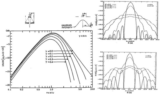
Figure 1.
(Left) Far-field gain of a centrally obscured but focused optical telescope with a primary mirror diameter equal to 2a and a secondary mirror diameter (if any) equal to 2b as a function of the ratio α = a/w, where w is the beam waist radius and the ratio of the secondary and primary diameters is γ = b/a. (Upper right) Far-field pattern of an unobscured telescope (γ = 0) without defocusing (solid line) and with two levels of defocusing (2 dashed lines). (Lower right) Same as upper right figure but with a secondary mirror (γ = b/a = 0.2).
4. Interplanetary Laser Communications
The present author has previously analyzed the system requirements for transmitting a given data rate via a 532 nm laser link between Earth and other planets within the solar system [6]. The results are summarized in Figure 2, which plots the laser link requirements (i.e., the transmitted laser power multiplied by the product of the transmit and receive telescope diameters squared) on the y-axis versus the distance between the Earth and the planetary terminal on the x-axis. Each of the four lines represents a different data rate, i.e.,1 Mbps, 10 Mbps, 100 Mbps, and 1 Gbps. The mean distance between Earth and the various planets within our solar system are indicated by the labelled black dots (within our solar system at the frequency-doubled Nd:YAG wavelength of 532 nm). The corresponding y values for other wavelengths λ can be obtained by simply multiplying the y-axis values in Figure 2 by (λ/532 nm)2. Clearly, shorter wavelengths imply lower transmitted laser powers and/or smaller telescopes, but they also imply narrower beams and more stringent coalignment between collaborating telescopes.
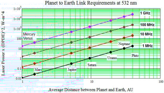
Figure 2.
The product of the transmitted laser power emitted by the planetary probe and the two interacting planetary transmit (DP) and Earth receive telescope (DE) diameters squared (y-axis) is plotted as a function of the planetary distance (x-axis) for a wavelength of 532 nm and four candidate bit rates: 1 MHz (black), 10 MHz (red), 100 MHz (brown), and 1 GHz (pink). The dots along the lines indicate the average distance of the planet from Earth. The chart can be used for other wavelengths by multiplying the y-axis number by .
The laser power requirements in Figure 2 assume a simple On–Off Keying (OOK) approach, i.e., a series of ones (photons detected in the bit time interval) or zeros (inadequate photons detected in the bit time interval), as described in [6]. From Figure 2, we can obtain the value of PT (DTDR)2 needed for a 16-beam, 4 Mbit/sec link at 532 nm between the various planets and Earth [2] in units of Watt-m4, i.e., 0.04 (Mercury, Venus), 0.07 (Mars), 0.7 (Jupiter), 4.0 (Saturn), 8.0 (Uranus), 40 (Neptune), and 60 (Pluto). Of course, for the more distant planets, one could reduce the number of beams from 16 to lower the required data rates and/or place most of the link burden on the Earth receive telescope diameter DR.
5. Quasi-Continuous Communication Links via Synchronized Parallel Orbits
Quasi-continuous laser communications between Earth and the planet being mapped minimizes the buildup of stored information, the need for frequent reacquisition of interplanetary connections, and bursts of data transfers to Earth at much higher data rates. However, uninterrupted laser communications between Earth and other planets in the solar system are not possible whenever the two planets and the Sun are collinear, i.e., whenever the two planets are on opposite sides of the Sun and are therefore blocked or when they are on the same side of the Sun and the intense solar background overwhelms one of the two terminals. Nevertheless, “quasi-continuous” communications are possible if the planetary probe and Earth terminal are placed in parallel orbits perpendicular to their common orbital plane about the Sun. However, since the rotation axes of the planetary poles are not typically oriented perpendicular to the planetary orbital plane about the Sun, some areas around the poles may not be mapped without later revisions to the orbit of the mapping satellite.
In Figure 3, the maximum point-ahead angle occurs when the Earth and the planet are on opposite sides of the Sun (180°). This is due to the fact that (1) the range between them, and therefore the light travel time, is maximized, and (2) their orbital velocities are in opposite directions, and therefore, the relative velocity is additive. The point-ahead angles decrease for the outer planets because of their slower angular velocities. Smaller secondary peaks occur at 0° (or 360°) for all the planets because (1) the orbital velocities are in the same direction, and therefore, the relative velocity is reduced, and (2) the light travel time is minimized. Intermediate angles where the point-ahead angle drops to near zero would be advantageous for mutual acquisition of the two terminals and occur twice per Earth year.
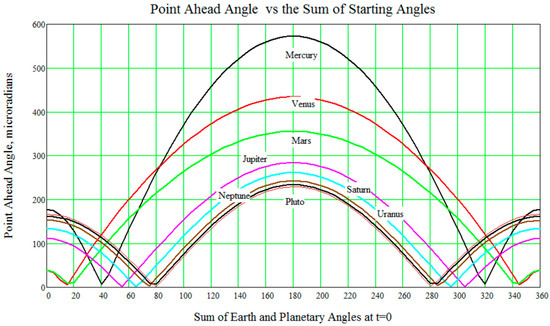
Figure 3.
Terminal point-ahead angle in microradians for the various planets in the solar system when viewed from Earth versus the sum of their angular positions in their orbits about the Sun [6].
As an example, Figure 4 illustrates the manner in which an Earth–Mars link would be initially established when the angle ψ is approximately 17° and the point-ahead angle is zero, thereby enabling the Earth orbiter to use the sunlit Mars surface to initially locate the mapping satellite. The figure shows the geometry of the initial acquisition of the planetary satellite at t = 0 and at a later time t. The triangle in green between the Sun, Earth, and Mars has two known side dimensions corresponding to the radii of the two planetary orbits (RE and RM) and the opposing angle (π-ψ), thereby allowing the distance between the two satellites during acquisition to be computed and listed in Table 1 for all of the planets.
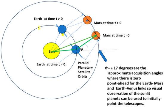
Figure 4.
Earth–Mars example. Initial coalignment of the Earth terminal with the mapper at Mars takes place after the satellite pair have been placed in parallel orbits perpendicular to the common orbital plane about the Sun. When the two planets reach the geometry in the figure where the angle ψ between the Earth–Mars line and the Sun–Earth line is approximately ±17 degrees; the point-ahead angle for both terminals is roughly zero.

Table 1.
The acquisition distances are typically not much larger than the minimum distance between Earth and the planet of interest allowing for stronger laser signals between the terminals.
At the time of acquisition, the vector between the planets is normal to the two orbits, but, as time goes on, the orbits remain parallel but the vector between them is no longer perpendicular to the orbits. Assuming circular orbits for both planets about the Sun, one can also estimate the length of time between solar interruptions of the data flow. From Figure 4, we have the following equations for the angular positions of the Earth and planetary mapping satellite
The Sun physically blocks the beam whenever is approximately equal to nπ, where n is an odd integer and blinds the terminal farthest from the Sun when n is an even integer. Thus, the time interval between solar interruptions is given by
and the planets closest to Earth have the longest interval between solar blockages. However, the interplanetary communications link can also be blocked by the planets themselves if the satellite altitudes are too low. Furthermore, the blocking intervals are extended somewhat if the two orbits are asynchronous, as illustrated on the right side of Figure 5. Orbits are defined as synchronous if their periods and phase are equalized, as in the left side of Figure 5. Since planets have unequal masses, the satellite altitude about the planet being mapped must be chosen to match the angular speed of the Earth terminal. Thus, lidars mapping planets of lower mass than Earth will operate at a lower altitude than the Earth orbiter and vice versa.
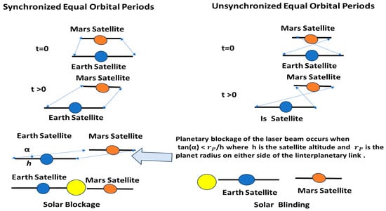
Figure 5.
When both the period and phase of the two orbits are matched (synchronous orbits), the satellites always have mutual visibility, except as they (1) approach a configuration where the Sun either blocks transmission or blinds the terminal farthest from the Sun (Mars) or (2) the beams are blocked by the host planets themselves. In the latter case, blockage duration can only be reduced by increasing the Earth and planetary satellite altitudes such that they maintain the same orbital period and phase, i.e., based on planetary mass.
Figure 5 also indicates that communications between Earth and planetary satellites will not be interrupted by the host planets themselves when
where α is the angle that the vector makes between the two parallel orbital planes and h = nprp is the satellite altitude expressed as a multiple of the planetary radius rp. If np = 1, then α = 45° and planetary blockage of the planet to Earth communications link occurs roughly half the time, implying the need for substantial onboard data storage and a doubling of the communications data rate when the link is unblocked. Thus, to substantially extend the measurement period without significantly increasing onboard data storage and interplanetary bit rate requirements, one must fly the Earth and planetary terminals at a much higher altitude. On the negative side, the higher orbital altitudes will (1) significantly increase the number of bits per lidar measurement to achieve the same surface height resolution, thereby resulting in greater onboard data storage and interplanetary data transmission requirements, and (2) place increased burdens on the planetary lidar link to be discussed in the next section.
6. The Lidar Link Equations for the Various Planets in Our Solar System
The ICESat-2 laser produced a 5 W beam of 1.5 nsec pulses at a rate of 10 kHz. Thus, each pulse contained 500 µJ of energy, with each photon representing 3.73 × 10⁻²⁰ J at the frequency-doubled Nd:YAG laser wavelength λ = 532 nm. If we assume equal energies per beamlet, the received photons per pulse per beamlet is given by the equation
where nT =1.34 × 10¹² photons (500 µJ at 532 nm) are transmitted per pulse; nb is the number of beamlets; the product represents the typical optical efficiencies of the lidar transmit and receive optics and the single-photon-sensitive detector, respectively; gT = 1.12 and gR = 1 are the optimum geometric efficiencies of a common transmit/receive lidar telescope with no secondary mirror [4,5]; Ap = πD2/4 is the area of the common transmit/receive telescope primary lens; λ = 532 nm is the ICESat-2 lidar wavelength; h = nprp is the lidar orbital altitude, expressed as a multiple of the planetary radius rp; Tatm2 is the two-way atmospheric transmission of the planetary atmosphere; ρs is the reflectance of the planetary surface illuminated by the laser; and is the surface slope.
The original experimental spaceborne single-photon-sensitive lidar proposed by the present author in 2002 and presented to the NASA ICESat-2 team in 2006 consisted of 16 equal beamlets generated by a single 10 kHz laser providing up to 160,000 surface measurements per second [2]. NASA originally proposed to fly the proposed system as an experiment alongside a copy of the 40 pps multiphoton, single-beam, GLAS lidar that had previously flown on ICESat-1. However, funding issues later forced the ICESAt-2 science team to choose a modified version of the 16-beam single-photon-sensitive lidar that utilized three “strong” and three “weak” beams, where the “strong” beams contained four times the energy of the “weak” beams. The need for “strong” beams was primarily driven by (1) a strong solar background when ranging over highly reflective snow and ice areas like Greenland and (2) the desire to determine tree heights within dense canopies, which provided significant attenuation of the lidar beam [3]. While the latter situations are not expected to be an issue when mapping other planets within our solar system, clouds of gases in their atmospheres and surface reflectivity will still attenuate the solar and laser radiation equally when the solar and lidar line of sight to the planetary surface coincide. However, as illustrated in Figure 5, the mapping orbits discussed previously lie in a plane normal to the planet’s orbital plane about the Sun; therefore, solar/lidar path coalignment only occurs twice per planetary orbit, and only when the projection of the satellite orbital plane intersects the Sun, i.e., at or near the two solar blocking events described in Figure 5.
The solar power density entering the Earth’s atmosphere at the laser wavelength of 532 nm has been shown to be about SE(λ) = 1.8 W/(sec-m2-nm) = 1.8 Joule/(sec-m2-nm) = 4.81 × 10¹⁸ photons/(sec-m2-nm). Thus, the solar photon count at the edges of other planetary atmospheres would be given by
where RE and Rp are the orbital radii of the Earth and planet about the Sun. Since the collinear lidar beam and solar photons see the same lidar receive telescope optics, detector, atmosphere, and surface reflectivity, the worst-case number of solar photons collected within the ATLAS laser pulsewidth (τp = 1.5 nsec) is given by
The worst-case solar intensity at the laser wavelength as it encounters the Earth’s atmosphere is given by SP(λ) Δλ, where Δλ = 10 nm is the lidar filter bandwidth and RE and RP are the radii of the planetary orbits about the Sun. The lidar pulse is always directed normal to the nominal surface of a spherical planet but, with the satellite’s orbital plane perpendicular to the planet’s orbital plane about the Sun, solar rays are usually oriented at a large angle relative to the surface normal. Therefore, the vast majority of solar photons do not enter the lidar telescope until the satellite’s orbital plane comes close to intercepting the Sun. Even then, only a fraction of the satellite orbit facing the Sun is subject to a strong solar background. In any event, the worst-case lidar Signal-to-Noise Ratio (SNRwc) can be obtained by dividing Equation (7) by Equation (9), yielding
High satellite altitudes (h = nprp) positively affect the time interval over which the Earth and planetary satellite stations can maintain contact for data transfer, while negatively impacting the SNR and spatial resolution of the planetary lidar link due to the increased range to the surface unless one compensates with a large transmit/receive telescope. The fraction of time that interplanetary laser communications can be conducted without being interrupted by planetary blockage of the beam is given by
where tan(α) = h/rp = np and F = 0.5, 0.71, 0.80, 0.84, 0.88 for np = 1, 2, 3, 4, 5, respectively. Thus, for np = 1, the blocked and unblocked conditions have the same duration and occur alternately at 90° intervals, with the center of the first unblocked interval coinciding with the acquisition configuration illustrated in Figure 4. For np = 2, the angular range of unblocked intervals increases from 90° to 128° and the blocked periods are reduced from 90° to 52°. For np = 3, the angular range of unblocked intervals increases to 144° and the blocked periods are reduced to 36°. Clearly, however, there are diminishing returns from onboard data storage and interplanetary transfer standpoints, as np increases while the lidar return signal strength decreases much more rapidly (by the factor 1/).
Table 2 attempts to provide some insight into what a copy of the ATLAS lidar might accomplish in terms of the worst-case SNR for the various planets in our solar system. The relatively high worst-case SNR values per beamlet listed in the final two columns of the table suggest that the number of beamlets nb can be traded against the satellite orbital height np (length of mapping time per orbit) or, in the case of the most distant planets (e.g., Saturn, Uranus, and Neptune), increased while still maintaining the high orbit. However, the extreme distances of the outer planets from Earth places a much larger burden on the interplanetary laser communication bandwidth, as was previously illustrated in Figure 2. On the other hand, planets farthest from the Sun also see a much lower solar background. Thus, the reduced solar noise and slower velocity of the high-altitude orbit potentially allows a greater number of beamlets and, therefore, greater resolution of the planetary topography in both the along-track and cross-track directions. The term “separate beamlets” could also refer to a simpler optical configuration in which a single ATLAS beam (1) divided into a square array of equal power beamlets generated by a diffractive device and imaged onto a pixelated, single-photon detector such as a segmented anode photomultiplier or a SPAD array, as previously utilized in high-altitude airborne lidars [7] or (2) an unmodified single-beam return imaged onto a multipixel array detector. In the latter case, the central pixel would see the maximum number of photon returns, while the surrounding pixels would see reduced but adequate photon counts because of the nominally Gaussian shape of the transmitted beam in Figure 1. As can be seen from the same figure, where the spatial intensity of the beam is plotted on a logarithmic scale in db, optimum truncation of the Gaussian beam (α = a/w = 1.12) by the circular telescope aperture diverts a very small fraction of the laser power to the weak rings surrounding the strong central lobe. This option will be discussed further in the next section.
Table 2.
The effects of planetary distance from the Sun (RP), the radius of the planet (rP), and the orbital height (h = nprp), on the worst-case Signal-to-Noise Ratio (SNRwc), assuming a lidar utilizing the ATLAS laser and a transmit/receive telescope with a primary area Ap = 0.5 m2 (diameter = 0.8 m) but producing nb beamlets and operating at much higher altitudes (h = nprp) than the 500 km ICESat-2 orbit.
7. Planetary Surface Resolution and Continuity
The relatively high worst-case SNR values in the last two columns of Table 2 suggest that a large number of beamlets, or alternatively a single large area beam viewed by a large number of pixels, nb = na2 are feasible, especially at lower satellite altitudes. Low values of nP imply (1) lower orbits and higher orbital speeds and (2) a reduction in the time available for transferring the lidar data back to Earth and a corresponding need for onboard data storage and faster interplanetary communication links. On the positive side, the low orbits permit more beamlets (or detector pixels) and therefore higher spatial resolution of the surface per pulse. Thus, one final factor that impacts our choice of the integers nb and nP is the spatial resolution, distribution, and continuity of the planetary terrain measurements. As the satellite altitude (h = nPrp) increases, the lidar beam area at the surface increases as , thereby decreasing spatial resolution and lowering the SNR by allowing fewer lidar photons and more solar photons into the receiver. At the same time, the velocity of the satellite also decreases according to the formula
where G = 6.6743 × 10⁻¹¹ m3 kg−1s−2 is the Gravitational Constant, MP is the planetary mass in kg, and h = nPrP is the satellite altitude in km. From Equation (3), the lidar beam area on the planetary surface is approximately equal to
where rs is the radius of the circular surface area adequately illuminated by the lidar and, as before, Ap = 0.5 m2 is the ATLAS lidar telescope primary aperture. We now assume that the lidar return is imaged onto a square detector array containing nb = na2 pixels monitoring a central square subtended by the radius rs, as in Figure 6. This implies that
or
where δ represents the along-track and cross-track dimensions of the square on the ground observed by a single detector pixel in the pixelated lidar detector. Table 3 displays the various values for planets in our solar system. Combined with the SNR results in the last column of Table 2, the results suggest that topographic resolutions in the along-track and cross-track directions at the decimeter level are quite possible, at least for the four planets closest to the Sun. For the outer planets, meter-level resolution is feasible but, as indicated by Figure 2, the interplanetary communications link becomes much more challenging due to the high laser powers and large telescope apertures needed to achieve the necessary data rates.
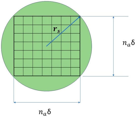
Figure 6.
Instead of splitting the lidar beam into separate beamlets, one can choose to image the lidar return onto a square, single-photon-sensitive detector array such as a segmented anode MCP/PMT or a SPAD array. This provides high spatial resolution in both the along-track and cross-track dimensions. The array dimension naδ is chosen to fit within a radius rs of the Gaussian beam where (1) the reduced SNR for the outer pixels is acceptable and (2) continuous coverage in the along-track dimension is maintained, i.e., vPΔt = naδ.
Table 3.
Computation of the satellite velocities and pixelated ground dimensions for the various planets assuming the same laser power (500 mW), pulse repetition rate (10 kHz), and primary lidar telescope aperture (Ap = 0.5 m2r) as the ATLAS lidar on ICESat-2. The manner in which the satellite altitude h = nprp affects the results is also indicated.
8. Establishment of the Interplanetary Laser Communications Link
It is assumed that the Earth and planetary satellites are each equipped with two coaligned telescopes attached to a common pointing platform and dedicated to the interplanetary transfer of wideband planetary lidar data. One of the planetary telescopes is dedicated to transmitting 10 Megabits per second or more lidar data to the Earth terminal, while the coaligned receive telescope uses a detector array to center a beacon laser transmitted by the Earth terminal. Meanwhile, the Earth terminal receive telescope receives and stores the transmitted lidar data for later transfer to the designated Earth station(s), while the transmit telescope provides the laser beacon to optimize and maintain the optical coalignment of the two terminals. It is further assumed that the transmit telescopes can be defocused temporarily, if necessary, to allow a larger search beam during the coalignment process.
If the altitudes of the two cooperating satellites are known and initial coalignment of the two optical systems takes place when the point ahead angles between the planets are zero, as described in Figure 3 and Figure 4, the wavelength filtered (e.g., 532 nm) sunlit image of the planet is centered on a single-photon-sensitive multipixel detector similar to that used in the pixelated lidar measurements. Laser pulses from the satellite will then be contained within a narrow ring of known radius about the full or partial planetary image within the detector array. If each terminal points its transmitter at a portion of that ring, the other terminal can fixate on the opposite terminal most quickly by scanning the ring in the opposite direction of the planetary satellite movement. However, if the two orbits are quasi-synchronized in both period and phase, as recommended previously, the signal from the opposite terminal will fall within a very small segment of the circle common to both satellites, further simplifying the coalignment. Once acquired, the beacon or lasercom beam can be centered in the array and kept there by monitoring the adjacent pixels, as is currently done in NASA’s single-photon-sensitive Space Geodesy Satellite Laser (SGSLR) stations using reflections from retroreflector arrays mounted on distant Earth-orbiting satellites [8] Finally, in the event that the coalignment is temporarily lost during operations and the point ahead angle is no longer zero, defocusing the transmit telescopes enough to compensate for the known point-ahead angles in Figure 3 can aid in regaining the coalignment.
9. Concluding Remarks
While, because of cloud cover and other atmospheric conditions, conventional microwave communications systems may be best suited to collect and transmit high data rates periodically relayed by the Earth orbiter to cooperating ground stations, lasers are better suited to broadband interplanetary communications due to the λ2 wavelength dependence mentioned in the caption to Figure 2. It is therefore assumed that, in addition to the high data rate Earth-to-ground communications terminal, the Earth-orbiting relay satellite also carries additional instrumentation in support of the interplanetary laser communications link. As illustrated in Figure 7, this would include a coaligned transmit and receive optical telescope unit and controller, a laser beacon for the planetary orbiter to lock onto, a high-data-rate interplanetary laser communications receiver, and a high-capacity data storage unit to collect and store planetary lidar data during periods when interplanetary links are blocked by the Sun or planets themselves. As discussed previously, the length of these periods depends on the choice of satellite altitudes (h = nPrP) due to planetary blocking of the signal path. For nP =1, signal blocking occurs when the angle α in Figure 5 is less than 45°, i.e., 50% of the time, thereby doubling the required data transmission rate. While the duration of these blocking periods can be lessened somewhat by utilizing higher orbits (Equation (6)), the higher orbits have a much stronger negative impact (1/nP2) on both the overall lidar SNR (Equation (10)) and the attainable ground resolution for a given laser power and lidar telescope primary aperture Ap (Equation (14b)).
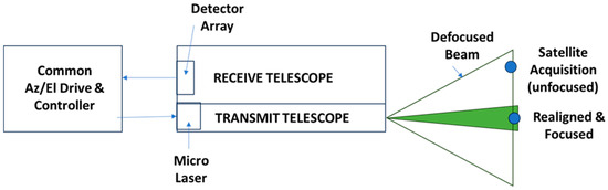
Figure 7.
The Earth terminal for the wideband laser communications link consists of coaligned transmit and receive telescopes on a common gimbal mount directed by a detector array used for both initial opposite terminal acquisition and telescope reception of the wideband data. It is assumed that the transmit telescope on both terminals can be defocused to aid in the initial acquisition and coalignment of the two terminals.
It should also be noted that, according to Figure 2, the required product of laser power times the diameters of the planetary transmitting and Earth receiving telescope squared (PDP2DE2) increases dramatically for the planets beyond Saturn. For example, if we assume a product (DpDE) = 1 m2 for the Earth receive and planetary transmit telescopes and a desired data transfer rate of 10 Mbps, the laser power requirement at the 532 nm wavelength increases from 0.1 Watt for Mercury and Venus to 10 W for Saturn and 100 W for Neptune. As for the telescope diameters, most of the burden can be placed on the Earth orbiting platform. For example, NASA’s 2.2 m Hubble telescope, which operated for years and was routinely serviced by astronauts in Earth orbit, would require a 45 cm diameter transmit telescope to achieve the 1 m2 product. Increasing the planetary telescope diameter by a factor of 2 to 90 cm would reduce the laser power requirement by a factor of 4, i.e., to 2.5 W for Saturn and 25 W for Neptune.
Reducing Data Storage and Transmission Bandwidth Requirements: One could also reduce bandwidth requirements by recording and transmitting the full range recorded by the central pixel and the range difference for the remaining pixels, which would require significantly fewer bits for large arrays. For example, if we assume a 10 × 10 array (na = 10) containing 100 pixels, a satellite operating at an altitude four times the radius of Mars (nP = 4 or h = 13,560 km), with a desired height resolution per pixel of 0.1 m, each pixel would require n = 24 bits (2n > 4h/0.1 m = 1.3560 × 10⁸) to record the distance to the ground, plus an additional 7 bits (27 = 128) to identify the pixel. Thus, 100 pixels at the ATLAS pulse rate of 10 kHz would result in a rather high data yield of 31 Mbps. However, as described in the final column of Table 3, the spacing between two adjacent pixels for our Mars example is given by
where 10 cm is our desired range resolution. Thus, a vertical displacement between adjacent pixels greater than δ would imply a slope 45 degrees and an adjacent pixel return diminished by a factor of cos(θs). Thus, if we retain adjacent returns (if any) differing in range by as much as 4 bits, this would imply a rather steep slope up to roughly 66 degrees between adjacent pixels. If we now only transmit the difference in range for the 99 pixels surrounding the central pixel, the bits per outer pixel would be reduced from 31 to 7 + 4 =11 bits, resulting in a 64 percent reduction in data rate, i.e., [31 + 99(11)] × 104 bps = 11.2 Mbps compared to 31 Mbps.
Relaying Data to an Earth Ground Station: Ultimately, the data collected by the Earth satellite via the interplanetary link must be transferred to a ground station at a high data rate. Because the Earth interplanetary terminal is orbiting in a plane orthogonal to the orbital plane of the Earth about the Sun, long-term quasi-continuous data transfer to a ground station can be accomplished via a second Earth satellite in a geosynchronous orbit, which, at an altitude of hg = ngrE = 35,786 km (where ng = 5.62 Earth radii), is in constant contact with the ground station. It is interesting to note that the geosynchronous value ng = 5.62 is comparable to the values of nP considered in Equation (11) for the orbital synchronization of the two planetary terminals and would result in a blocking percentage between the two planetary terminals of only 10%. If also adopted for the space-to-ground link, the value nP = 5.62 would allow the space-to-ground orbit to be synchronized with the orbits of the two planetary terminals and uninterrupted by the Earth itself; however, the desirability of this approach for a given planetary mission would require a more detailed examination.
Finally, given the orders of magnitude shorter link distances and the vulnerability of a laser link to clouds and other atmospheric effects, this space-to-ground transmission is probably best implemented using conventional microwave systems. Nevertheless, link blockage between two unsynchronized Earth-orbiting satellites will occur whenever the line between the geosynchronous satellite and the Earth terminal intersects the Earth.
Interplanetary Laser Communications Progress to Date: Almost two decades ago, using a 1.2 m telescope at Goddard Space Flight Center in Greenbelt MD, NASA demonstrated a one-way laser link to the Mars Orbiter Laser Altimeter (MOLA) over a distance of 80 million km [9] and a two-way link to the Messenger spacecraft en route to Mercury at a distance of 22 million km [10]. In 2016, a high-bandwidth, free-space laser communication link was established between Earth and the Moon by NASA’s Lunar Laser Communications Development (LLCD) program. LLCD demonstrated a data downlink of 622 Mbps and an error-free downlink of 20 Mbps [11]. Even more recently, in December 2023, wideband laser communications links were successfully established between multiple ground-based Earth stations and the NASA Psyche spacecraft at Mars. Data transfer rates up to 267 Mbps over distances of 307 million miles were achieved as part of NASA’s Deep Space Optical Communications Experiment (DSOC). Since the Earth terminals were ground-based, Earth’s rotation about its polar axis and/or atmospheric conditions periodically interrupted the laser link but, over time, a total pf 136 Terabits of data was successfully transferred [12]. Shortly thereafter, the European Space Agency (ESA) also successfully established a transmission–reception optical link with NASA’s DSOC experiment onboard its Psyche spacecraft, located 265 million kilometers away, using two ground stations in Greece [13]. For the most recent review of deep space optical communications technology citing 247 articles, the reader is referred to a paper published in 2025 [14].
Funding
This research received no external funding.
Data Availability Statement
No inaccessible external data was used in the generation of this document.
Conflicts of Interest
Author declares no conflict of interest.
References
- Bolcek, J.; Barakat, M.; Gibril, A.; Veverka, J.; Sloboda, J.; Marsalek, R.; Slobod, S.; Gotthans, T. Spaceborne LiDAR Systems: Evolution, Capabilities, and Challenges. Sensors 2025, 25, 3696. [Google Scholar] [CrossRef] [PubMed]
- Degnan, J.J. Photon Counting Multkilohertz Microlaser Altimeters for Airborne and Spaceborne Topographic Measurements. J. Geodyn. 2002, 34, 503. [Google Scholar] [CrossRef]
- Degnan, J.J. Evolution of Single Photon Lidar: From Satellite Laser Ranging to Airborne Experiments to ICESat-2. Photonics 2024, 11, 924. [Google Scholar] [CrossRef]
- Klein, B.J.; Degnan, J.J. Optical Antenna Gain 1: Transmitting Antennas. Appl. Opt. 1974, 13, 2134–2141. [Google Scholar] [CrossRef] [PubMed]
- Degnan, J.J.; Klein, B.J. Optical Antenna Gain 2: Receiving Antennas. Appl. Opt. 1974, 13, 2397–2401, Erratum in Appl. Opt. 1974, 13, 2762. [Google Scholar] [CrossRef] [PubMed]
- Degnan, J.J. Multipurpose Laser Instrument for Interplanetary Ranging, Time Transfer, and Wideband Communications. Photonics 2023, 10, 98. [Google Scholar] [CrossRef]
- Degnan, J.J. Scanning, Multibeam, Single Photon Lidars for Rapid, Large Scale, High Resolution, Topographic, and Bathymetric Mapping. Remote Sens. 2016, 8, 958. [Google Scholar] [CrossRef]
- McGarry, J.F.; Hoffman, E.D.; Degnan, J.J.; Cheek, J.W.; Clarke, C.B.; Diegel, I.F.; Donovan, H.L.; Horvath, J.E.; Marzouk, M.; Nelson, A.R.; et al. NASA’s satellite laser ranging systems for the twenty-first century. J. Geodesy 2018, 93, 2249. [Google Scholar] [CrossRef] [PubMed]
- Abshire, J.B.; Sun, X.; Neumann, G.A.; McGarry, J.F.; Zagwodzki, T.W.; Jester, P.; Riris, H.; Zuber, M.; Smith, D. Laser Pulses from Earth Detected at Mars. In Proceedings of the 2006 Conference on Lasers and Electro-Optics and 2006 Quantum Electronics and Laser Science Conference, Long Beach, CA, USA, 21–26 May 2006; Optica Publishing Group: Washington, DC, USA, 2006; pp. 1–2. [Google Scholar]
- Smith, D.E.; Zuber, M.T.; Sun, X.; Neumann, G.A.; Cavanaugh, J.F.; McGarry, J.F.; Zagwodzki, T.W. Two Way Laser Link over Interplanetary Distance. Science 2006, 311, 53. [Google Scholar] [CrossRef] [PubMed]
- Cornwell, D. Space-based Laser Communications Break Threshold. Opt. Photonics News 2016, 27, 24–31. [Google Scholar] [CrossRef]
- Available online: https://www.reddit.com/r/space/comments/1nkrt9v/nasas_deep_space_communications_demo_exceeds/ (accessed on 25 September 2025).
- Available online: https://www.esa.int/Enabling_Support/Operations/Europe_s_first_deep-space_optical_communication_link (accessed on 25 September 2025).
- Karmous, S.; Adem, N.; Atiquzzaman, M.; Samarakoon, S. How Can Optical Communications Shape the Future of Deep Space Communications? A Survey. IEEE Commun. Surv. Tutor. 2025, 27, 725–747. [Google Scholar] [CrossRef]
Disclaimer/Publisher’s Note: The statements, opinions and data contained in all publications are solely those of the individual author(s) and contributor(s) and not of MDPI and/or the editor(s). MDPI and/or the editor(s) disclaim responsibility for any injury to people or property resulting from any ideas, methods, instructions or products referred to in the content. |
© 2025 by the author. Licensee MDPI, Basel, Switzerland. This article is an open access article distributed under the terms and conditions of the Creative Commons Attribution (CC BY) license (https://creativecommons.org/licenses/by/4.0/).