Abstract
In this paper, we propose and experimentally demonstrate a dual-parameter fiber optic sensor, which combines a Fabry–Perot interferometer (FPI) and a Mach–Zehnder interferometer (MZI) for simultaneous pressure and temperature sensing. The Fabry–Perot (FP) cavity is formed by sandwiching a capillary fiber between a single-mode fiber and a dual-core fiber (DCF). A fluid channel is very close to the central core of the DCF. By precisely drilling micro-air chambers in the annular cladding of a capillary fiber (CF) using a femtosecond laser, external air pressure can directly affect the capillary fiber and induce changes in the refractive index of the air in the CF. The F-P cavity achieves a pressure sensitivity of 3.67 nm/MPa with a temperature cross-sensitivity of 2.82 pm/°C. The MZI is constructed using a dual-core fiber filled with silicone oil in the fluidic channel, which enhances temperature sensitivity through the thermo-optic effect. The MZI sensor exhibits a nonlinear temperature response with an average sensitivity of 103.43 pm/°C. The corresponding pressure cross-sensitivity is about –0.11 nm/MPa. Due to very low cross-sensitivity, simultaneous measurement of temperature and gas pressure is feasible. In addition, we implement a variant by replacing silicone oil with a UV-curable adhesive, which delivers a comparable FP-based pressure sensitivity of ~3.93 nm/MPa while yielding an MZI-based temperature sensitivity of 71.7 pm/°C and potentially improved long-term stability.
1. Introduction
Optical fiber sensors have been widely studied and applied in both academic and industrial domains due to their inherent advantages, including high sensitivity, compact size, corrosion resistance, immunity to electromagnetic interference, and suitability for remote monitoring. Among these, fiber optic air pressure sensors have garnered significant attention in applications such as industrial automation and biomedical diagnostics [1,2,3,4,5,6,7]. However, their performance is often compromised by temperature cross-sensitivity, which introduces errors in precise air pressure measurements. To tackle this challenge, dual-parameter optical fiber sensors capable of simultaneously detecting both air pressure and temperature have been actively developed over the past two decades [8,9].
A variety of dual-parameter fiber optic sensors have been developed based on the combination of different sensing mechanisms. These include cascaded fiber Bragg gratings (FBGs) [10,11,12], FBGs combined with Fabry–Perot interferometers (FPIs) [13,14,15], FBGs integrated with Mach–Zehnder interferometers (MZIs) [16], dual FPI configurations [17,18,19,20], MZI-MZI combinations [21], and MZI-FPI hybrid structures [22,23]. These sensors utilize the complementary sensing characteristics of each element to achieve simultaneous measurement of air pressure, temperature, or other physical parameters. The dual-FBG structure achieves dual-parameter measurement by cascading two FBG sensors in the optical fiber, each used to measure pressure and temperature, respectively. For example, in 2022, Xu et al. [24] proposed a compact sensor based on two FBGs mounted on a diaphragm-lever structure for simultaneous temperature and pressure sensing. Although FBGs have been widely adopted in dual-parameter sensing schemes due to their compact size and well-established fabrication techniques, their intrinsic pressure sensitivity remains relatively low (e.g., ~28 pm/MPa in Ref. [24]). In 2011, Wu et al. [25] reported a hybrid sensor incorporating FBGs written in single-mode fibers (SMFs) and grapefruit-shaped micro-structured fibers (GMFs) to enhance pressure response. However, the GMFs feature complex fabrication processes and limited reproducibility, which restricts their production scalability.
Compared to pure FBG-based configurations, hybrid structures combining FBGs with interferometric elements, such as FPIs, have also attracted increasing attention for dual-parameter sensing, owing to the high sensitivity of FPIs to pressure and their compact cavity design, which enables efficient decoupling of temperature and pressure effects. In 2019, Liu et al. [26] developed a simple FBG-cascaded polymer FPI sensor, in which the FPI was fabricated by applying a UV-curable polymer cap on the FBG end face, resulting in a compact structure capable of simultaneous temperature and pressure sensing. The sensor exhibited high sensitivities of 223.4 pm/°C for temperature sensing and 24.99 nm/MPa for gas pressure sensing, enabling accurate dual-parameter measurement within the range of 30–110 °C and 0.1–0.7 MPa. In 2024, Liang et al. [27] demonstrated an FBG-FPI sensor using femtosecond laser micromachining and the Vernier effect, achieving stable operation up to 700 °C. Nevertheless, this sensor exhibited relatively low temperature sensitivity, with the FBG showing a sensitivity of only 12.4 pm/°C, while the pressure sensitivity reached 18.66 nm/MPa at room temperature and 6.09 nm/MPa at 700 °C.
In addition, the FBG-MZI hybrid structure has also gained attention as a promising approach for dual-parameter sensing, where FBG is used for temperature measurement and MZI offers high sensitivity for pressure detection, along with a simple fabrication process and flexibility in structural design. In 2021, Li et al. [16] proposed a hybrid optical fiber sensor for simultaneous measurement of gas pressure and temperature, based on an MZI cascaded with an FBG. In their design, a tapered SMF segment was inserted between two multimode fibers (MMFs) to form the MZI structure, which served as the gas pressure sensing element. An FBG was subsequently cascaded with the MZI to compensate for temperature-induced wavelength shifts. While this approach demonstrated the feasibility of dual-parameter sensing, a notable limitation lies in the comparable temperature sensitivities of both the MZI and FBG components. Such similarity increases the risk of cross-sensitivity between the two parameters.
Regarding dual-FPI-based configurations, in 2020, Fu et al. [28] proposed a simple yet highly sensitive FPI sensor based on polydimethylsiloxane (PDMS), by fusion splicing a hollow capillary with a single-mode fiber and injecting PDMS to form a three-reflection-surface structure. The sensor achieved a temperature sensitivity of 2.62 nm/°C and a pressure sensitivity of 20.63 nm/MPa, demonstrating excellent dual-parameter sensing capabilities with a simple and compact design. Ma et al. [29] demonstrated a cascaded FPI sensor by integrating a sapphire-derived fiber (SDF) and an SMF within a silica capillary sealed with CO2 laser welding. This structure enabled simultaneous pressure and temperature sensing, achieving a pressure sensitivity of 5.19 nm/MPa and a temperature sensitivity of 0.013 nm/°C at temperatures up to 700 °C. In addition to the FPI-based configuration, MZI-MZI hybrid structure has received attention due to its high sensitivity to both pressure and temperature. In 2022, Yang et al. [21] developed a single-fiber temperature–pressure sensor that integrates dual MZIs, utilizing PDMS coating and side-polishing techniques to form dual interference paths, showing a temperature sensitivity of −1.19 nm/°C for the first MZI and a pressure sensitivity of −3.96 nm/MPa for the second MZI, respectively. Although the FPI-FPI and MZI-FPI structures exhibit high sensitivity, when both temperature and pressure change simultaneously, they may interfere with the interference signal, making the decoupling of the two parameters challenging. To effectively separate these two physical quantities, more complex demodulation methods are often required, or a multi-channel measurement system may be necessary
In this paper, we propose a dual-parameter fiber optic sensor, which integrates an FPI and an MZI for simultaneous pressure and temperature sensing. The F-P cavity and the MZI spectra are monitored simultaneously from the reflection and transmission port of the sensor probe, which would avoid spectral overlap and facilitate monitoring of resonance peaks. The sensor is fabricated by cascading an SMF, a capillary fiber (CF), a dual-core fiber (DCF), an MMF, and another SMF via fusion splicing. In this sensor structure, the CF constitutes the F-P cavity, while the DCF forms the MZI. A micropore is drilled on the surface of the CF using the femtosecond laser to allow air to go through. Changes in environmental air pressure would induce variations in the refractive index of air in the CF, thus resulting in spectral shifts in the F-P interference spectra. Simultaneously, temperature variations alter resonant peak shifts in the MZI transmission spectra. Thanks to a fluid channel beside the central core of DCF, materials with high thermo-optic coefficients infiltrated into the channel could improve the temperature sensitivity. First, silicone oil is infiltrated into the channel, and experimental results show that the F–P cavity achieves an air pressure sensitivity of 3.67 nm/MPa with an almost neglectable sensitivity of ~2.82 pm/°C. The MZI exhibits an average temperature sensitivity of 103.43 pm/°C and a pressure cross-sensitivity of 0.11 nm/MPa. By independently tracking spectral shifts in the FPI for pressure sensing and the MZI for temperature sensing, accurate and decoupled measurements of both parameters can be achieved. This is enabled by the inherently low cross-sensitivities of each sensing mode (≤3%), which allows the minor influence of pressure on the MZI and temperature on the F–P cavity to be regarded as negligible error terms, thus eliminating the need for complex decoupling algorithms. In addition, to potentially improve the long-term stability of the probe, silicone oil is replaced by a UV-curable adhesive, showing a pressure sensitivity of ~3.93 nm/MPa and a temperature sensitivity of ~71.7 pm/°C.
2. Sensor Fabrication Optical
The fabrication process of the proposed fiber optic sensor with silicone oil infiltrated into the DCF fluid channel is illustrated in Figure 1. First, an SMF pigtail was spliced to a CF (Polymicro TSP100170, Polymicro Technologies, Phoenix, AZ, USA) using a fusion splicer (FSM-100P, Fujikura Inc., Tokyo, Japan) with manual mode, and the CF was cleaved to a length of ~150 μm with the aid of a microscope. The inner diameter of capillary is ~102 μm and the outer diameter is ~141 μm. During the fusion, the discharge position was offset toward the SMF side to avoid collapse of the CF, which would form the F-P cavity. Then, another SMF pigtail was spliced to an MMF in automatic mode, and the MMF was cleaved to ~3 mm. Finally, a segment of DCF (Yangtze Optical Electronic Co., Ltd., Wuhan, China, [30,31]) was sandwiched between these two components, forming SMF-CF-DCF-MMF-SMF sensor structures. In the DCF, the cladding diameter is ~125 μm, with core diameters of ~8.1 μm (central core) and ~9.2 μm (eccentric core), and the fluid channel diameter is ~36 μm. Figure 2 shows the actual microscopic image of the fusion splice between the DCF and capillary fiber, clearly revealing the alignment and interface quality. To allow external gas pressure to directly interact with the inner cavity of the F-P structure, a micrometer-scale air hole was drilled into the sidewall of the capillary fiber using an fs-laser micromachining system [23]. Prior to fusion splicing, silicone oil was infiltrated into the DCF fluid channel via capillary action until it was filled to ~6 cm, and the fiber was cleaved to ~10 cm, ensuring ~2 cm of oil-free length at each end to avoid oil burning in the following fusion process. The reason that this DCF is used to constitute the MZI is explained as follows. The transmitted light from the F-P cavity would be coupled to the two cores, which inherently constitute the sensing arm and reference arm of the MZI. In addition, the fluidic channel in the DCF could accommodate a tiny amount of thermally sensitive fluid and only has an influence on the guided modes in the center core via thermos-optic effects rather than the modes in the eccentric core, as detailed in Section 3. Thus, it is unnecessary to immerse the fiber probe in thermally sensitive materials exposed in the external environment, which may suffer from contamination or degradation. Also note that in the following multiple experimental tests of air pressure and temperature characterization, we have not observed any leakage of the infiltrated oil from the DCF. Additionally, to potentially improve long-term stability, UV-curable adhesive was used as a substitute for silicone oil. In this case, the adhesive could be cured after infiltration in the DCF and permanently immobilized inside of the fluidic channel of DCF. Particularly, the DCF was spliced to the MMF-SMF segment in manual mode with the discharging position offset to the MMF side, and then to the SMF-capillary segment with the discharging position offset to the DCF side, thus completing the full sensor structure. In these fusion splicing processes, the discharge power and duration were finely adjusted to avoid thermal damage; a typical setting of discharge strength was –0.4 mA (this particular Fujikura fiber splicer uses current to represent the discharge power) with a main discharge time of 300 ms. Figure 3 illustrates the overall structure of the temperature and pressure sensor based on the SMF-CF-DCF-MMF-SMF configuration.
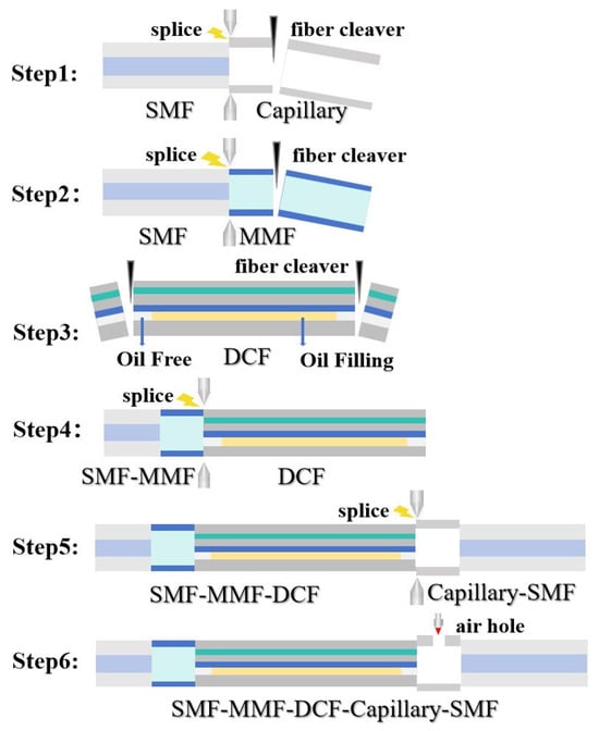
Figure 1.
The manufacturing process of the sensor.
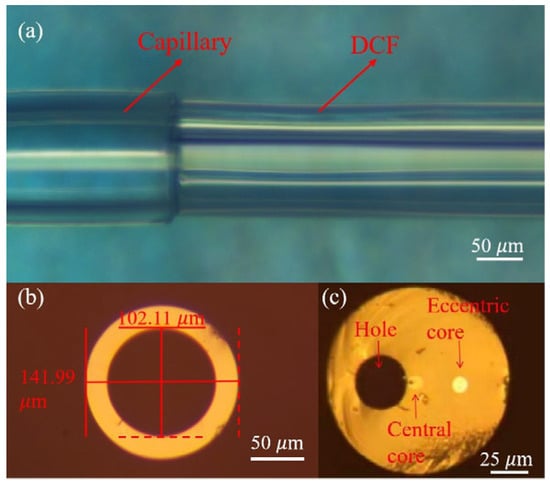
Figure 2.
(a) Microscopic image of the fusion joint between the DCF and the CF, (b) cross section of the CF, and (c) cross section of the DCF.
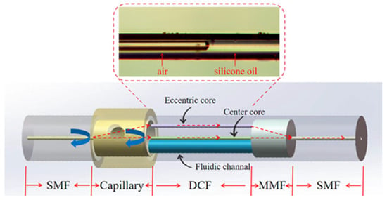
Figure 3.
Schematic illustration of the SMF-CF-DCF-MMF-SMF structure of the temperature and pressure sensor.
As shown in Figure 4a, the capillary wall was intact prior to the drilling process. The fs-laser with a central wavelength of 520 nm, a pulse duration of 346 fs, and a pulse energy ~1.6 μJ was operated at a repetition rate of 5 kHz. After precise focusing and irradiation, a square-shaped air hole with dimensions of approximately 10 μm × 10 μm was successfully drilled, as shown in Figure 4b. The fabricated micropore exhibited well-defined edges with no observable thermal damage or cracking around the perforation area, confirming that the high precision and minimal heat-affected zone was achieved by femtosecond laser processing.

Figure 4.
(a) Before femtosecond laser drilling and (b) after femtosecond laser drilling.
3. Operation Principle of the Sensor
The sensor proposed here features an SMF-MMF-DCF-CF-SMF structure which constitutes the in-line F-P and the M-Z fiber interferometer, and the optical paths of the FPI (reflection spectrum) and MZI (transmission spectrum) in the sensor are shown in Figure 3.
Particularly, the CF constitutes an F-P cavity, and the two parallel reflecting surfaces of this F-P cavity are the interface, M1, of the SMF and the capillary, and the interface, M2, of the CF and DCF. The CF is communicated with the external air pressure through the micropore. Therefore, the refractive index in the F-P cavity changes with environmental air pressure, so that the resonant wavelengths (interference dip) would shift in response to different air pressures. Based on this principle, the sensor can realize pressure sensing with details explained in the following section.
For the reflection surface with near vertical incidence and low reflectivity (~4% for air–silica interface), multi-beam interference can be simplified as two-beam interference, with reflected light intensity given by [29]
where and are light intensities reflected by the two reflecting surfaces, respectively. is the phase difference in F-P between interface M1 and M2, which can be expressed as the following [29]:
where denotes the wavelength, is the refractive index of the air in the F-P cavity, and is the cavity length. The condition for the interference dip occurrence is satisfied when the phase difference meets
where is an integer. According to Equations (2) and (3), the wavelength condition at the interference dip is
The refractive index-to-pressure correlation follows the Edlén formula, in which air refractive index is a function of pressure and temperature [32]:
According to Equation (5), pressure variations induce refractive index changes in the optical fiber sensor, thus leading to interference dip wavelength shifts; however, influence of thermal variations on refractive index is virtually negligible. On the other hand, in practical sensor deployments, temperature fluctuations could induce F-P cavity length variations through thermal expansion or contraction, thus causing spectral drift and degrading pressure sensing stability. Thus, for air pressure sensing, temperature compensation is therefore essential.
Transmitted light of the F-P cavity would be relayed to the DCF-MMF-SMF segment, and the MZI will be realized in the DCF, in which the eccentric core and the center core are, respectively, used as the reference arm and the sensing arm in the MZI. The two beams propagating along the dual-core fiber are recombined in the MMF and finally enter the SMF and are transmitted to the demodulator (HBM Fibersensing, FS22SI). The refractive index of silicone oil will change with temperature, which makes the transmission spectrum drift and enables temperature sensing.
Intensity of the transmitted light is represented as the following [26,32]:
where and is the transmitted intensity of eccentric core and center core; is the phase difference in light conducted between eccentric core and center core, which can be expressed as the following [30]:
In Equation (7), is source wavelength, and denote the lengths of air- and silicone-oil-filled DCF segments, respectively. The effective index difference corresponds to the air-filled DCF segment between the eccentric and center cores, while applies to the silicone-oil-filled segment. They could be calculated by Equations (8) and (9):
where are the effective indices of guided modes in the center core and the eccentric core in the air-filled segment of the DCF, and are the counterparts in the oil-filled segment of the DCF. From Equations (6) and (7), it can be seen that the transmission spectrum of the sensor presents periodic amplitude disturbance, and the position of spectral drift can be defined as follows [30]:
where in Equation (10) is an integer. The change in temperature will cause the change in refractive index and length of silica, air, and silicone oil in the DCF. The thermo-optic coefficient of silicone oil is () [30], significantly exceeding those of silica and air (both ). The thermal expansion coefficient of silica is , which is smaller by two orders when calculating the variations in differences in optical path length (OPL) of the guided mode in the two cores. Moreover, thermal expansion of the two cores would offset with each other [30] when calculating the difference in phase of the light traveling along the dual cores, and thus could be neglected. Therefore, when the ambient temperature changes, it mainly changes the refractive index of silicone oil and then affects the effective refractive index of the guided mode in the central core (adjacent to the fluid channel), while the effective refractive index of the eccentric core guided mode (far away from the fluid channel) is barely affected. So in Equation (10) can be ignored, and only changes with the temperature, thus leading to interferometric dip shifts in the transmission spectra. On the other hand, variations in air pressure may lead to a change in , and thus slightly shift the transmission spectrum.
From the discussion above, the wavelength shift ( and ) of the FPI and MZI under varying air pressure and temperature are expressed as the following [33]:
where , , , and are the temperature sensitivity and pressure sensitivity of the reflection spectrum and transmission spectrum, respectively. Thus, gas pressure and temperature are decoupled into the matrix form:
Here, , and are in units of , kPa, and pm, respectively. The kPa unit ensures a consistent order of magnitude in the matrix. As shown, simultaneous monitoring of both parameters is achieved by combining the sensor’s sensitivity coefficients with the wavelength shift.
4. Experimental Results
The temperature measurement setup is shown in Figure 5. We immobilized the sensor on the temperature-controlled breadboard (PTC1, Thorlabs, temperature range: 30–45 °C). The SMF pigtail on the CF end connected with Channel 1 of the demodulation, while the SMF pigtail on the MMF end connected to Port 1 of the fiber optic circulator. Subsequently, Port 2 of the circulator interfaced with Channel 0 of the spectral demodulator (HBM FS22SI, HBM Fibersensing, Porto, Portugal). The transmission spectrum can be acquired via Channel 0 of the demodulator, and the reflection spectrum can be measured via Channel 1.
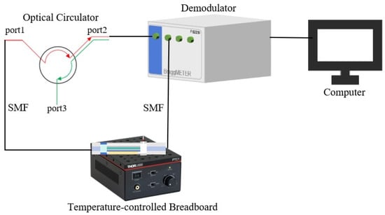
Figure 5.
Experimental setup for temperature sensor characterization.
The air pressure characterization setup is shown in Figure 6. The measurement system consists of a demodulator, an optical fiber circulator, a flange-sealed pressure barrel, and a variable-frequency air compressor. The entire sensor was placed inside the pressure vessel, and both ends of the sensor were connected to the outside via optical fiber pigtails. The reflective and transmissive ends of the sensor were then connected to the demodulator through the corresponding optical fiber pigtails. The transmission and reflection spectra were simultaneously acquired through Channels 0 and 1 of the demodulator, respectively.
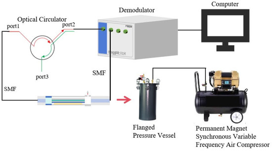
Figure 6.
Experimental setup for pressure sensor characterization. The red arrow indicates that the optical fiber sensor is placed inside the flange-sealed tank.
In the temperature range of 31 °C to 45 °C, the heating and cooling cycles were conducted at intervals of 1 °C. Once the breadboard temperature stabilized at each set point, the transmission and reflection spectra were collected, and measurements were repeated five times at each temperature point. Regarding pressure, the air pressure varied from 0.1 MPa to 0.6 MPa, with cyclical pressure variations at intervals of 0.1 MPa. The transmission and reflection spectra were recorded after each set of atmospheric pressure values was stabilized, and five repeated measurements were performed.
To characterize the temperature response of the MZI-based sensor, we recorded the transmission spectrum in the wavelength range of 1500–1600 nm (see Figure S1 in the Supplementary File) and the interference dip near ~1507 nm was selected for wavelength shift tracking, as shown in Figure 7a. Figure 7(b1) presents a zoomed-in view of this specific dip, which was used for detailed wavelength shift tracking. Moreover, the temperature sensitivity is wavelength dependent; a side-by-side comparison between the dips near ~1507 nm and ~1554 nm is provided in the Supplementary File (Figure S2), and it showed greater spectral shifts at ~1507 nm. This dip exhibits a sharp resonance and significant spectral shift under temperature changes, which facilitates reliable tracking and repeatable identification during the sensing process. The transmission spectra exhibit a noticeable redshift with increasing temperature. The consistent spectral shift across the measured temperature range ensures the accurate evaluation of the sensor’s thermal response. Notably, the wavelength drift observed in the transmission spectrum during temperature variation is significantly greater than that induced by pressure, further confirming the suitability of this feature for temperature demodulation. Figure 7(b2) shows the pressure response of the MZI-based sensor at a wavelength around 1507 nm, and the full spectral evolutions are shown in Figure S3 of the Supplementary File. It is obvious that MZI-based sensors are insensitive to the change in air pressure.
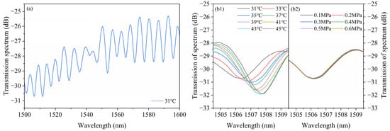
Figure 7.
Transmission spectra of the MZI-based temperature sensor. (a) Transmission spectra over the wavelength range of 1500–1600 nm at the temperature of 31 °C; (b1) evolution of the spectral dip near ~1507 nm at the air pressure of 0.1 MPa over the temperature range of 31–45 °C at 2 °C intervals; and (b2) evolution of the spectral dip near ~1507 nm at the temperature of 31 °C over the pressure range of 0.1–0.6 MPa at 0.1 MPa intervals.
To evaluate the air pressure response of the FPI-based sensor, we also recorded the reflection spectra within the range of 1500–1600 nm (see Figure S4 in the Supplementary File), and the interference dip near ~1570 nm in the reflection spectrum was selected for wavelength shift tracking, as shown in Figure 8a. This dip was chosen because it resides in a spectral region with high fringe contrast and minimal distortion, maintaining a sharp, symmetric profile across all pressure levels. Figure 8(b1) displays a distinct redshift with increasing pressure, and the dip around ~1570 nm shows the most prominent and consistent shift. Figure 8(b2) shows the reflection spectrum around 1570 nm of the FPI in response to temperature, and the full spectral evolutions are shown in Figure S5 in the Supplementary File. It is obvious that the FPI is insensitive to the change in temperature. This confirms that the F-P sensor exhibits excellent pressure sensitivity with minimal temperature cross-sensitivity.

Figure 8.
Reflection spectra of the FPI-based pressure sensor. (a) Reflection spectra over the wavelength range of 1500–1600 nm under pressure at 0.1 MPa; (b1) partial evolution of the reflected spectrum near ~1570 nm, measured over the pressure range of 0.1–0.6 MPa at 0.1 MPa intervals; and (b2) partial evolution of the reflected spectrum near ~1570 nm, measured over the temperature range of 31–45 °C.
As shown in Figure 9a, temperature and pressure responses of the MZI are compared by tracking the wavelength shift from a representative dip in the transmission spectrum. The temperature-induced wavelength shift of the MZI section follows a quadratic dependence (), indicating a strong and nonlinear temperature response. By linear fit, the average temperature sensitivity of the MZI sensor is 103.43 pm/°C. In contrast, the MZI structure demonstrates a weak air pressure response, with a sensitivity of only −0.11 nm/MPa. This weak response may be caused by the changes in from the DCF.
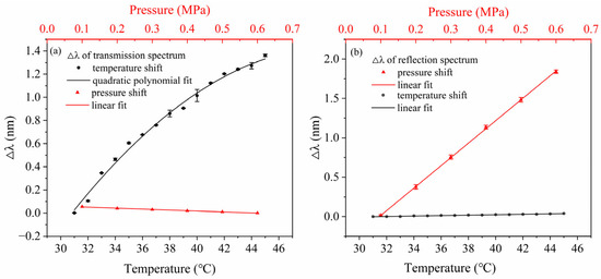
Figure 9.
(a) Wavelength shift of the spectral dip at ~1507 nm of the MZI structure with temperature and pressure rising, showing minimal thermal sensitivity to pressure. (b) Wavelength shift of the spectral dip at ~1570 nm of the FPI structure with repeated measurements due to the changes in pressure and temperature.
Figure 9b presents a comparison of the pressure and temperature responses of the FPI sensing section. The FPI exhibits a pronounced wavelength shift with increasing pressure, yielding a sensitivity of 3.67 nm/MPa with an R2 of 0.9998. In contrast, when the temperature changes, the FPI section shows a minimal reaction with a slope of 0.00282 nm/°C and an R2 value of 0.97617, confirming its thermal insensitivity within the tested range. These results indicate that the temperature sensitivity of the sensor is primarily attributed to the MZI structure.
These results confirm that pressure sensing is mainly dominated by the FPI, while the temperature sensing is entirely contributed by the MZI, thus realizing the effective separation of the two parameters. This is consistent with the previous findings that using silicone oil-filled dual-core optical fibers or other materials with high thermal optical coefficients can significantly improve the temperature sensitivity [30,31], which further proves that using the built-in MZI structure combined with such materials is an effective strategy to enhance the thermal response of the sensor.
The temperature and air pressure characterization experiments were repeated five times to verify the repeatability of the sensor. The error bars for the wavelength shift at designated wavelengths in the FPI and MZI, under variations in temperature and pressure, are presented in Figure 9a,b, respectively, confirming the consistency of the measured wavelength shifts.
For the F–P cavity, the pressure sensitivity is 3.67 nm/MPa, while the temperature-induced shift is 2.82 pm/°C. Considering that the MZI exhibits an average temperature sensitivity of 103.43 pm/°C, the F–P cavity’s temperature cross-sensitivity can be calculated as follows:
Similarly, for the MZI structure, the pressure-induced shift is 0.11 nm/MPa, while the F–P structure responded to pressure with a sensitivity of 3.67 nm/MPa. Thus, the MZI’s pressure cross-sensitivity is as follows:
The cross-sensitivities are less than 3% of the target parameter sensitivities they correspond to, so they can be regarded as errors. It means that complicated matrix calculation is not needed to separate these changes in air pressure and temperature. Specifically, the F-P cavity exhibits high sensitivity to pressure variations, while its response to temperature changes is negligible, allowing the spectral shift from its interference dip to serve as a reliable indicator of gas pressure. Conversely, the MZI structure demonstrates a strong response to temperature changes due to the thermo-optic effect of the silicone oil-filled dual-core fiber, whereas its pressure sensitivity is minimal and can be ignored. Thus, by independently monitoring the spectral shift in the FPI for pressure sensing and the MZI for temperature sensing, the proposed sensor system achieved effective dual-parameter measurement without requiring complex matrix-based decoupling. This simplified approach enhances both the intuitiveness and robustness of the sensing process, making it well-suited for real-time applications in dynamic environments.
The above experimental results verify that the performance of our sensor is relatively stable and repeatable and confirm its significance in practical applications. To assess the effect of thermosensitive materials on MZI sensitivity and long-term stability, another sensor was fabricated with the same structure and similar dimension parameters, and the silicone oil in the MZI channel was replaced by the UV-curable adhesive (NOA 132; Norland Products Inc., Cranbury, NJ, USA). The injection of UV glue followed the same procedure as that for silicone oil. Then, the UV glue was completely cured inside the fluidic channel of the DCF using a UV lamp.
To characterize the temperature response of the MZI-based sensor, we recorded the transmission spectrum in the wavelength range of 1500–1600 nm (see Figure S6 in the Supplementary File) and the interference dip near ~1540 nm was selected for wavelength shift tracking, as shown in Figure 10a. Figure 10(b1) presents a zoomed-in view of this specific dip, which was used for detailed wavelength shift tracking. Figure 10(b2) shows pressure response of the MZI-based sensor at wavelength around 1540 nm, and the full spectral evolutions are shown in Figure S7 in the Supplementary File. It is obvious that the MZI-based sensor is insensitive to the change in air pressure.

Figure 10.
Transmission spectra of the MZI-based temperature sensor. (a) Transmission spectra over the wavelength range of 1500–1600 nm at the temperature of 25 °C; (b1) evolution of the spectral dip near ~1540 nm at the air pressure of 0.1 MPa over the temperature range of 25–45 °C at 2 °C intervals; and (b2) evolution of the spectral dip near ~1540 nm at the temperature of 25 °C over the pressure range of 0.1–0.6 MPa at 0.1 MPa intervals.
To evaluate the air pressure response of the FPI-based sensor, we also recorded the reflection spectra within the range of 1500–1600 nm (see Figure S8 in the Supplementary File), and the interference dip near ~1545 nm in the reflection spectrum was selected for wavelength shift tracking, as shown in Figure 11a. Figure 11(b1) displays a distinct redshift with increasing pressure, and the dip around ~1545 nm shows the most prominent and consistent shift. Figure 11(b2) shows the reflection spectrum at around 1545 nm of the FPI in response to temperature, and the full spectral evolutions are shown in Figure S9 in the Supplementary File. It is obvious that the FPI is insensitive to the change in temperature. This confirms that the F-P sensor exhibits excellent pressure sensitivity with minimal temperature cross-sensitivity.

Figure 11.
Reflection spectra of the FPI-based pressure sensor. (a) Reflection spectrum over the wavelength range of 1500–1600 nm under pressure at 0.1 MPa; (b1) partial evolution of the reflected spectrum near ~1545 nm, measured over the pressure range of 0.1–0.6 MPa at 0.1 MPa intervals; and (b2) partial evolution of the reflected spectrum near ~1545 nm, measured over the temperature range of 25–45 °C.
As shown in Figure 12a, temperature and pressure responses of the MZI are compared by tracking the wavelength shift from a representative dip in the transmission spectrum. The temperature-induced wavelength shift in the MZI section follows a quadratic dependence (R2 = 0.9798), indicating a strong and nonlinear temperature response. The average temperature sensitivity of the MZI sensor is ~71.7 pm/°C. In contrast, the MZI shows a negligible response to applied air pressure within the tested range, confirming that the MZI channel functions effectively as the temperature-sensing element.
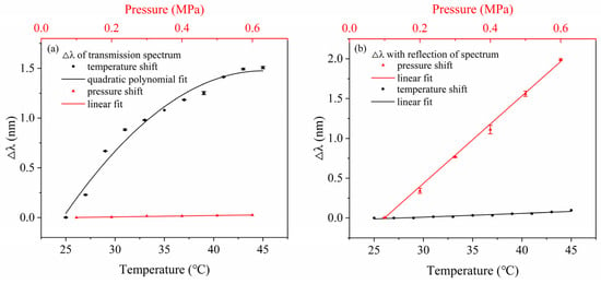
Figure 12.
Wavelength shift of the spectral dip at ~1540 nm of the MZI structure (a) and ~1545 nm of the FPI structure (b) with repeated measurements due to the changes in pressure and temperature.
Figure 12b presents a comparison of the pressure and temperature responses of the FPI sensing section. The FPI exhibits a pronounced wavelength shift with increasing pressure, yielding a sensitivity of ~3.93 nm/MPa with an R2 of 0.9998. In contrast, when the temperature changes, the FPI section shows a minimal reaction with a slope of 4.76 pm/°C, confirming its thermal insensitivity within the tested range. These results indicate that the temperature sensitivity of the sensor is primarily attributed to the MZI structure.
These results confirm that the pressure sensing is mainly dominated by the FPI, whereas the temperature sensing is entirely contributed by the MZI, achieving an effective separation of the two parameters. In contrast to silicone oil, the UV-curable adhesive adopted exhibits superior chemical and thermal stability, ensuring consistent optical performance during long-term operation. This further verifies that integrating a built-in MZI structure with a stable filling material is an effective approach to enhance the temperature response of the sensor.
5. Discussion
To further highlight the advantages of the proposed sensor, Table 1 summarizes its performance metrics in comparison with that of previously reported fiber optic sensors for simultaneous temperature and air pressure measurement. As we can see, the proposed FPI–MZI cascaded fiber optic sensor outperforms many previously reported dual-parameter temperature and air pressure sensors in several key aspects. Taking the proposed sensor with silicone oil as an example: for temperature measurement, the MZI in our design achieves a sensitivity of 103.43 pm/°C, which is significantly higher than that of dual-FBG-based designs such as those reported by Wu et al. [25] and Xu et al. [24], while maintaining an extremely low pressure cross-sensitivity (≤3%), thus effectively eliminating temperature–pressure coupling effects on measurement accuracy. For pressure measurement, the FPI exhibits a sensitivity of 3670 pm/MPa within the medium-to-low pressure range, while its temperature cross-sensitivity is only about 2.82 pm/°C, which is much lower than most reported structures. In contrast, designs such as those reported by Liu et al. [26] and Liang et al. [27], which rely on the Vernier effect or adhesive sealing, achieve higher pressure sensitivities but often suffer from larger cross-sensitivities, more complex decoupling processes, and limited stability under high-temperature conditions. In addition to the proposed sensor with silicone oil, the other proposed sensor with UV-curable adhesive presents comparable sensitivity and cross-sensitivity, except for the fact that the MZI temperature sensitivity is ~31% lower compared to the proposed sensor with silicone oil. This significant reduction may arise from the lower thermo-optic coefficient for the UV-curable adhesive.

Table 1.
Performance comparison of the proposed dual-parameter (temperature and air pressure) fiber optic sensor with previously reported counterparts.
Finally, we would like to note that variations in environmental humidity could also change the refractive index of the F-P cavity, thus leading to the spectrum shift. The influence of humidity on this sensor is virtually identical to that of the air pressure, since both air pressure and humidity would vary the refractive index of the F-P cavity. Therefore, performance of this sensor could be affected by the cross-sensitivity of humidity, which is a common problem of most fiber optic air pressure sensors using open cavities. Hence this sensor is preferred to operate in an environment where the humidity is relatively consistent; one could also use alternative humidity sensors together with some humidity compensation algorithms to improve environmental adaptability.
6. Conclusions
In summary, we have proposed a simple and sensitive optical fiber sensor for the simultaneous measurement of temperature and gas pressure by cascading a femtosecond laser-machined F-P cavity and an MZI using silicone-oil-filled DCF. The F-P cavity forms within the annular cladding of a capillary fiber and provides high-pressure sensitivity, while the silicone oil-filled MZI offers excellent temperature sensitivity through the thermo-optic effect. Due to the inherently low cross-sensitivities (≤3%) between temperature and pressure in each sensing mode, pressure and temperature can be independently extracted by directly tracking the F-P cavity peak shift and MZI valley shift, respectively. This eliminates the need for complex matrix-based decoupling and enables a more intuitive and robust sensing approach. We also used a UV-curable adhesive instead of silicone oil for long-term stability improvement. The proposed sensor enables the independent measurement of both gas pressure and temperature, offering advantages in terms of simplicity and accuracy. In terms of applications, the proposed sensor is not only suitable for fields with stringent requirements for pressure and temperature monitoring, such as industrial automation and the energy and petrochemical industries, but can also be applied to multi-parameter real-time monitoring in extreme environments, including environmental monitoring and aerospace. Its miniaturized, robust design makes it highly deployable in portable monitoring devices, distributed sensing networks, and complex, space-constrained environments, providing a feasible solution for multi-scenario and multi-domain sensing applications in the future.
Supplementary Materials
The following supporting information can be downloaded at: https://www.mdpi.com/article/10.3390/photonics12111047/s1, Figure S1. Transmission spectra of the MZ interferometer filled with silicone oil under different temperatures. Figure S2. Sensitivity comparison between ~1507 nm and ~1554 nm wavelength modes. Figure S3. Transmission spectra of the MZ interferometer filled with silicone oil under different pressures. Figure S4. Reflection spectra of the F-P cavity filled with silicone oil under different pressures. Figure S5. Reflection spectra of the F-P cavity filled with silicone oil under different temperatures. Figure S6. Transmission spectra of the MZI filled with UV-curable adhesive under different temperatures. Figure S7. Transmission spectra of the MZ interferometer filled with UV-curable adhesive under different pressures. Figure S8. Reflection spectra of the F-P cavity filled with UV-curable adhesive under different air pressures. Figure S9. Reflection spectra of the F-P cavity filled with UV-curable adhesive under different temperatures.
Author Contributions
Conceptualization, H.Q. and X.H.; methodology, H.Q. and X.H.; validation, X.C., C.T., X.G. and Q.H.; investigation, X.Z., T.Z. and P.-C.L.; writing—original draft preparation, X.Z. and T.Z.; writing—review and editing, H.Q. and X.H.; supervision, H.Q. and X.H.; funding acquisition, X.C., C.T., X.H. and H.Q. All authors have read and agreed to the published version of the manuscript.
Funding
This work was funded by the Natural Science Foundation of Guangxi Province (2023GXNSFDA026040), the National Natural Science Foundation of China (62475140), the Dongguan Science and Technology of Social Development Program (20221800905082), special projects in key fields of colleges and universities in Guangdong Province (2023ZDZX2063), the Guangxi Key Laboratory of Optoelectronic Information Processing (GD23203), and the Fonds de la Recherche Scientifique (F.R.S.-FNRS) under the Postdoctoral Researcher Grant (Chargé de Recherches) of Xuehao Hu.
Institutional Review Board Statement
Not applicable.
Informed Consent Statement
Not applicable.
Data Availability Statement
Data are contained within the article.
Conflicts of Interest
The authors declare no conflicts of interest.
References
- Dai, T.; Yi, Y.; Yi, Z.; Tang, Y.; Yi, Y.; Cheng, S.; Hao, Z.; Tang, C.; Wu, P.; Zeng, Q. Photonic crystal fiber based on surface plasmon resonance used for two-parameter sensing for magnetic field and temperature. Photonics 2024, 11, 784. [Google Scholar]
- Yang, X.; Song, Q.; Ma, C.; Yi, Z.; Cheng, S.; Tang, B.; Liu, C.; Sun, T.; Wu, P. A methane concentration sensor with heightened sensitivity and D-shaped cross-section U-shaped channel utilizing the principles of surface plasmon resonance. Phys. E 2024, 161, 115954. [Google Scholar] [CrossRef]
- Yang, X.; Yi, Y.; Lu, W.; Ma, C.; Yi, Z.; Li, G.; Zeng, L.; Zeng, Q.; Sun, T.; Ahmad, S. D-shaped photonic crystal fiber based on surface plasmon resonance for low refractive index applications. Opt. Mater. 2024, 153, 115612. [Google Scholar] [CrossRef]
- Yi, Y.; Yi, Z.; Zhou, Z.; Yang, H.; Wang, J.; Tang, C.; Deng, J.; Li, B. Structural design and analysis of D-type elliptical open-loop photonic crystal fiber temperature sensor based on SPR. Phys. B 2025, 715, 417549. [Google Scholar] [CrossRef]
- Rogers, K.R.; Poziomek, E.J. Fiber optic sensors for environmental monitoring. Chemosphere 1996, 33, 1151–1174. [Google Scholar] [CrossRef]
- Berthold, J.W. Industrial applications of fiber optic sensors. In Fiber Optic Sensors; Udd, E., Spillman, W.B., Eds.; Wiley: Hoboken, NJ, USA, 2011; pp. 349–371. [Google Scholar]
- Yu, Q.; Zhou, X. Pressure sensor based on the fiber-optic extrinsic Fabry-Perot interferometer. Photonics Sens. 2011, 1, 72–83. [Google Scholar] [CrossRef]
- Ran, Z.; Liu, S.; Liu, Q.; Huang, Y.; Bao, H.; Wang, Y.; Luo, S.; Yang, H.; Rao, Y. Laser-machined microcavities for simultaneous measurement of high-temperature and high-pressure. Sensors 2014, 14, 14330–14338. [Google Scholar] [CrossRef]
- Zhang, Y.; Huang, J.; Lan, X.; Yuan, L.; Xiao, H. Simultaneous measurement of temperature and pressure with cascaded extrinsic Fabry–Perot interferometer and intrinsic Fabry–Perot interferometer sensors. Opt. Eng. 2014, 53, 067101. [Google Scholar] [CrossRef]
- Jewart, C.M.; Wang, Q.; Canning, J.; Grobnic, D.; Mihailov, S.J.; Chen, K.P. Ultrafast femtosecond-laser-induced fiber Bragg gratings in air-hole micro-structured fibers for high-temperature pressure sensing. Opt. Lett. 2010, 35, 1443–1445. [Google Scholar] [CrossRef]
- Zhao, Q.; Zheng, H.; Lv, R.; Gu, Y.; Zhao, Y.; Yang, Y. Novel integrated optical fiber sensor for temperature, pressure and flow measurement. Sens. Actuators A Phys. 2018, 280, 68–75. [Google Scholar] [CrossRef]
- Wang, Y.; Tao, J.; Yuan, W.; Lian, Z.; Ling, Q.; Chen, D.; Yu, Z.; Lu, C. Hollow core Bragg fiber integrated with regenerate fiber Bragg grating for simultaneous high temperature and gas pressure sensing. J. Light. Technol. 2021, 39, 5643–5649. [Google Scholar] [CrossRef]
- Díaz, C.A.R.; Marques, C.A.F.; Domingues, M.F.F.; Ribeiro, M.R.N.; Frizera-Neto, A.; Pontes, M.J.; André, P.S.; Antunes, P.F.C. A cost-effective edge-filter based FBG interrogator using catastrophic fuse effect micro-cavity interferometers. Measurement 2018, 124, 486–493. [Google Scholar] [CrossRef]
- Fadeev, K.M.; Larionov, D.D.; Zhikina, L.A.; Minkin, A.M.; Shevtsov, D.I. A fiber-optic sensor for simultaneous temperature and pressure measurements based on a Fabry–Perot interferometer and a fiber Bragg grating. Instrum. Exp. Tech. 2020, 63, 543–546. [Google Scholar] [CrossRef]
- Yang, T.; Ran, Z.; He, X.; Li, Z.; Xie, Z.; Wang, Y.; Rao, Y.; Qiao, X.; He, Z.; He, P.; et al. Temperature-compensated multifunctional all-fiber sensors for precise strain/high-pressure measurement. J. Light. Technol. 2019, 37, 4634–4642. [Google Scholar] [CrossRef]
- Li, J.; Lin, H.; Zhou, A. Simultaneous measurement of gas pressure and temperature based on MZI cascaded with FBG. In Optical Fiber Sensors Conference 2020 Special Edition; Optica Publishing Group: Washington, DC, USA, 2021; p. W4.93. [Google Scholar]
- Yin, J.; Liu, T.; Jiang, J.; Liu, K.; Wang, S.; Qin, Z.; Zou, S. Batch-producible fiber-optic Fabry–Perot sensor for simultaneous pressure and temperature sensing. IEEE Photon. Technol. Lett. 2014, 26, 2070–2073. [Google Scholar]
- Xu, B.; Liu, Y.M.; Wang, D.N.; Li, J.Q. Fiber Fabry–Perot interferometer for measurement of gas pressure and temperature. J. Lightwave Technol. 2016, 34, 4920–4925. [Google Scholar] [CrossRef]
- Sun, B.; Wang, Y.; Qu, J.; Liao, C.; Yin, G.; He, J.; Zhou, J.; Tang, J.; Liu, S.; Li, Z.; et al. Simultaneous measurement of pressure and temperature by employing Fabry-Perot interferometer based on pendant polymer droplet. Opt. Express 2015, 23, 1906–1911. [Google Scholar] [CrossRef]
- Pang, C.; Bae, H.; Gupta, A.; Bryden, K.; Yu, M. MEMS Fabry–Perot sensor interrogated by optical system-on-a-chip for simultaneous pressure and temperature sensing. Opt. Express 2013, 21, 21829. [Google Scholar] [CrossRef]
- Yang, M.; Zhu, Y.; An, R. Temperature and pressure sensor based on polished fiber-optic microcavity. IEEE Photon. Technol. Lett. 2022, 34, 607–610. [Google Scholar] [CrossRef]
- Han, Y.; Liu, B.; Wu, Y.; Mao, Y.; Zhao, L.; Sun, T.; Nan, T.; Wang, J.; Tang, R. Fiber sensor based on Fabry-Perot/Mach-Zehnder hybrid interferometer for transverse load and temperature. Microwave Opt. Technol. Lett. 2021, 63, 679–684. [Google Scholar] [CrossRef]
- Zhu, X.; Jiang, C.; Chen, H.; Wang, Y.; Sun, S.; Zhang, H.; Wang, P.; Huang, A.H. Highly sensitive gas pressure sensor based on the enhanced Vernier effect through a cascaded Fabry–Perot and Mach–Zehnder interferometer. Opt. Express 2022, 30, 34956–34966. [Google Scholar] [CrossRef]
- Xu, D.; Feng, D.; Chen, Q.; Huo, D.; Qiao, X. Compact-packaged and diaphragm-lever structured fiber-optic temperature and pressure sensors for oil and gas well applications. IEEE Sens. J. 2022, 22, 22670–22677. [Google Scholar] [CrossRef]
- Wu, C.; Zhang, Y.; Guan, B.-O. Simultaneous measurement of temperature and hydrostatic pressure using Bragg gratings in standard and grapefruit micro-structured fibers. IEEE Sens. J. 2011, 11, 489–492. [Google Scholar] [CrossRef]
- Liu, Y.; Yang, D.; Wang, Y.; Zhang, T.; Shao, M.; Yu, D.; Fu, H.; Jia, Z. Fabrication of dual-parameter fiber-optic sensor by cascading FBG with FPI for simultaneous measurement of temperature and gas pressure. Opt. Commun. 2019, 443, 166–171. [Google Scholar] [CrossRef]
- Liang, R.; Zhu, H.; Zhu, X.; Guo, M.; Zhang, Q.; Su, Z.; Chen, J.; Hai, Z.; Zheng, Y.; Xue, C. FPI-FBG cascaded high-temperature pressure sensor up to 700 °C based on Vernier effect utilizing femtosecond laser. IEEE Sens. J. 2024, 24, 28818–28826. [Google Scholar] [CrossRef]
- Fu, D.; Liu, X.; Shang, J.; Sun, W.; Liu, Y. A simple, highly sensitive fiber sensor for simultaneous measurement of pressure and temperature. IEEE Photon. Technol. Lett. 2020, 32, 747–750. [Google Scholar] [CrossRef]
- Ma, Z.; Chen, J.; Wei, H.; Zhang, L.; Wang, Z.; Chen, Z.; Pang, F.; Wang, T. Compound Fabry–Perot interferometer for simultaneous high-pressure and high-temperature measurement. Opt. Express 2021, 29, 24289–24298. [Google Scholar] [CrossRef]
- Zhao, C.; Qiu, H.; Chen, H.; Hu, X.; Yu, Q.; Lian, Z.; Li, J.; Qu, H. In-fiber Mach–Zehnder temperature sensor using silicone-oil-filled dual core fiber. Sens. Actuators A Phys. 2021, 323, 112644. [Google Scholar] [CrossRef]
- Qiu, H.; Zhao, C.; Hu, X.; Chen, H.; Yu, Q.; Lian, Z.; Qu, H. Glycerol–water solution-assisted Mach–Zehnder temperature sensor in specialty fiber with two cores and one channel. Photonics 2021, 8, 103. [Google Scholar] [CrossRef]
- Zhang, X.; Xu, B.; Ma, X.; Zhang, Y.; Chen, H.; Jin, S.; Zhao, C.-L.; Wang, D.N.; Jiang, C. High sensitivity and low temperature cross-talk magnetic field sensor with ferrofluid-filled in-fiber Mach–Zehnder interferometer. Measurement 2024, 230, 114516. [Google Scholar] [CrossRef]
- Bauld, R.; Choi, D.-Y.W.; Bazylewski, P.; Divigalpitiya, R.; Fanchini, G. Thermo-optical characterization and thermal properties of graphene–polymer composites: A review. J. Mater. Chem. C 2018, 6, 2901–2914. [Google Scholar] [CrossRef]
Disclaimer/Publisher’s Note: The statements, opinions and data contained in all publications are solely those of the individual author(s) and contributor(s) and not of MDPI and/or the editor(s). MDPI and/or the editor(s) disclaim responsibility for any injury to people or property resulting from any ideas, methods, instructions or products referred to in the content. |
© 2025 by the authors. Licensee MDPI, Basel, Switzerland. This article is an open access article distributed under the terms and conditions of the Creative Commons Attribution (CC BY) license (https://creativecommons.org/licenses/by/4.0/).