Article

Coarse Integral Volumetric Imaging Display with Time and Polarization Multiplexing

1
College of Optics and Photonics, University of Central Florida, Orlando, FL 32816, USA
2
Department of Intelligent Interaction Technologies, University of Tsukuba, Tsukuba 3058573, Japan
3
Japan Society for the Promotion of Science, Chiyoda-ku, Tokyo 1020083, Japan
*
Author to whom correspondence should be addressed.
Photonics 2024, 11(1), 7; https://doi.org/10.3390/photonics11010007
Submission received: 19 November 2023 / Revised: 12 December 2023 / Accepted: 17 December 2023 / Published: 21 December 2023
(This article belongs to the Special Issue Liquid Crystals in Photonics)

Abstract

:
This paper introduces an innovative approach to integral volumetric imaging employing time and polarization multiplexing techniques to present volumetric three-dimensional images. Traditional integral volumetric imaging systems with a coarse lens array often face moiré pattern issues stemming from layered panel structures. In response, our proposed system utilizes a combination of time and polarization multiplexing to achieve two focal planes using a single display panel.

1. Introduction

Integral imaging, a long-established technique [1], stands as a prominent approach for achieving glasses-free three-dimensional (3D) displays, also known as autostereoscopic displays. Its notable feature lies in its ability to present true 3D images by reconstructing the light ray space, providing quasi-continuous parallax in both horizontal and vertical dimensions.
In traditional integral imaging [2,3,4,5,6], the number of views is in accord with the number of pixels covered by each elemental lens within the fly-eye lens sheet. This essentially establishes a one-to-one correlation where each elemental lens corresponds to one pixel. Alternative integral imaging methods using coarser lens arrays have been introduced as coarse integral imaging (CII) [7,8,9,10,11,12,13,14], where the elemental lens is large enough to cover dozens of times more pixels than the number of views. CII allows for the presentation of real or virtual images positioned off the screen, enabling the viewer to focus on them. Combining CII with volumetric imaging results in coarse integral volumetric imaging (CIVI), which enables the reproduction of multi-view stereoscopic images with greater depth and helps mitigate issues related to vergence–accommodation conflicts [14]. To address the noticeable seams between elemental images caused by the coarse lens array, Kakeya et al. proposed the incorporation of a weak diffuser, which introduces some blurring to the displayed image and increases the overall system size [15]. Another suggested solution involves implementing an interleaved structure of Fresnel lenses in the seam area of the elemental lenses to create smoother transitions [16]. More recently, researchers have introduced an approach in which the entire lens area is interleaved to achieve an efficient and consistent directional backlight for a time-multiplexed autostereoscopic display [17,18].
One of the issues encountered in CIVI is the low image quality due to multiple image planes [19]. Specifically, stacked liquid crystal display (LCD) panels have been traditionally utilized as layered image planes for volumetric imaging, leading to moiré patterns owing to their restricted pixel apertures.
Apart from employing layered LCD panels, multifocal lenses offer an alternative method for producing multiple image planes. Numerous multifocal lenses have been suggested for the realization of integral imaging systems. For instance, a bifocal lens array, which is capable of adjusting its focal length through electrical masking, can generate two central depth planes [20]. Dual-focal integral imaging can be achieved using a geometric phase lens [21] or a polarized liquid crystal lens [22], which falls under the category of polarization multiplexing approaches. This polarization multiplexing technique is also applicable in dual-view integral imaging systems [23] and integral imaging microscopes [24].
This paper introduces an innovative approach that employs time and polarization multiplexing to create two focal depths. This method enables the CIVI display to generate two image planes using a single LCD panel, thus avoiding the generation of moiré patterns. Furthermore, transitions between view images are smoothed by applying a fine interleaved Fresnel lens array.

2. Conventional Research

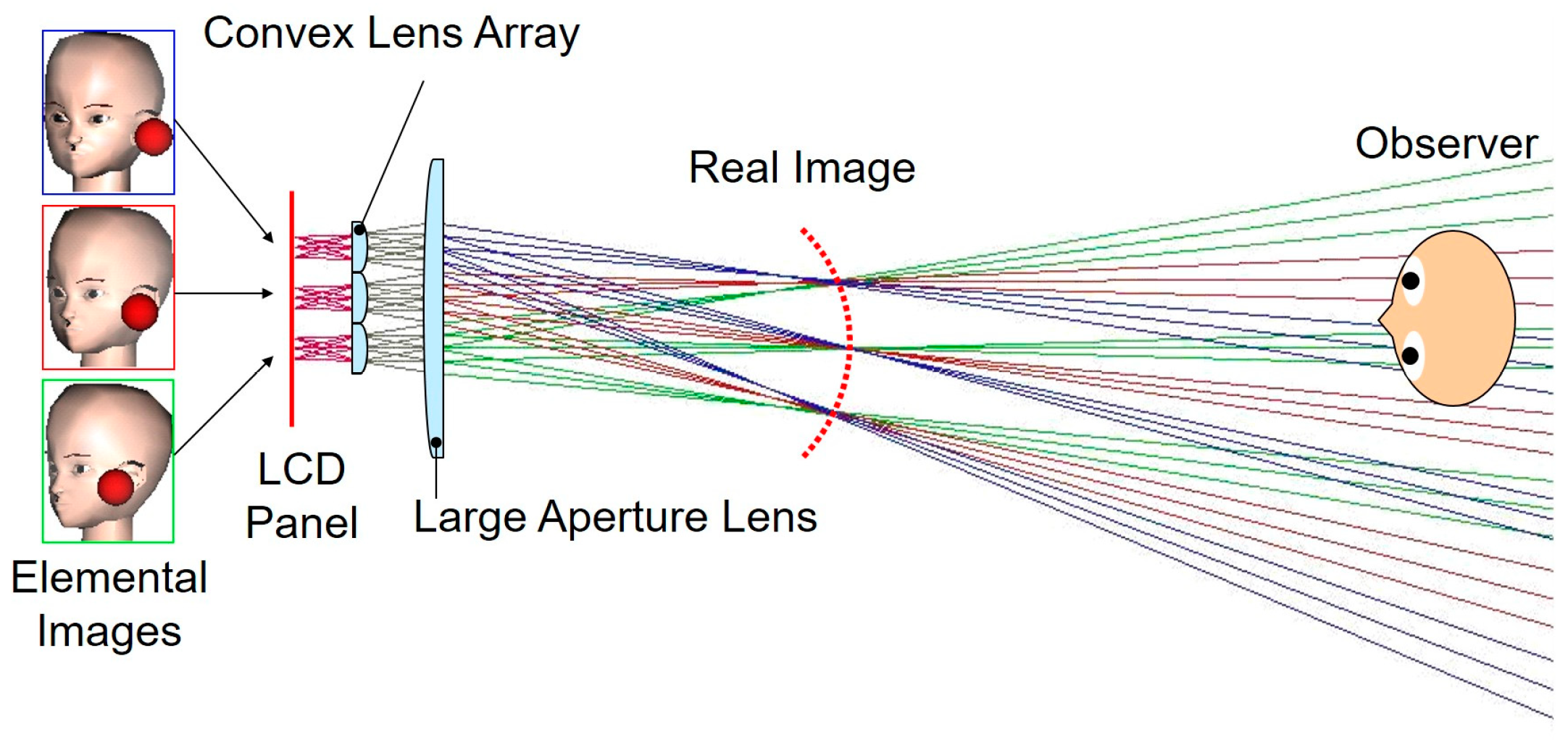
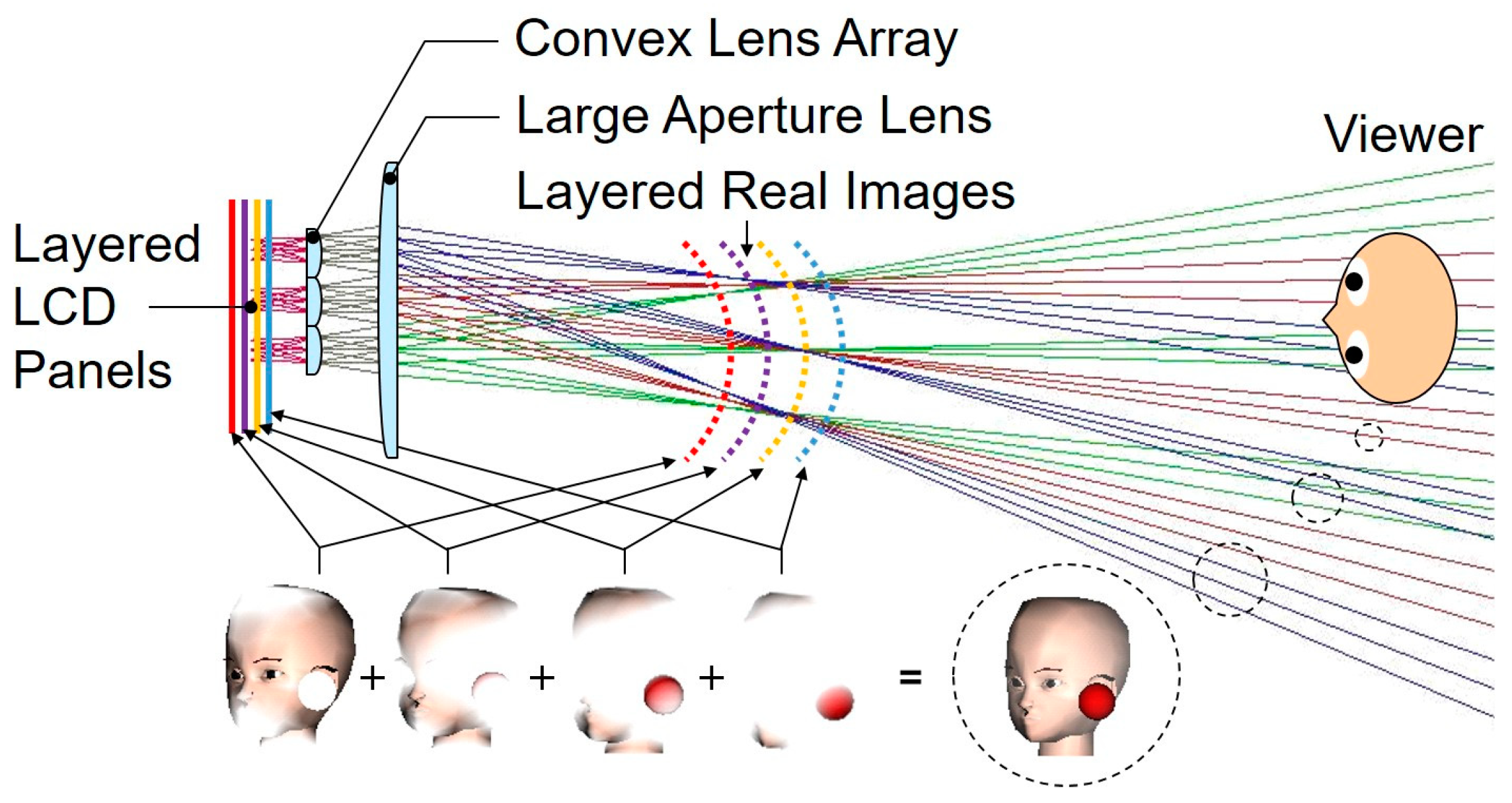
2.1. Coarse Integral Volumetric Imaging

CII is a variant of integral imaging in which the elemental lenses making up the fly-eye lens sheet are magnified, enabling multiple pixels to be perceived through a single lens by an observer [14]. The fundamental concept of CII is illustrated in Figure 1. To generate parallel light rays, the distance between the LCD panel and the lens array is set equal to the focal length of the latter. A large-aperture convex Fresnel lens is employed to distribute images of each view displayed on the LCD panel to each viewpoint, resulting in the creation of floating real images at its focal distance. Consequently, viewers can perceive both binocular parallax and motion parallax.
However, the effect of stereoscopy in a CII display depends on the parallax offered by multiple views, which can limit its capability to present the 3D images with substantial depth. To address this limitation, a CIVI has been introduced that combines the multi-view approach of CII with a volumetric solution [14]. In this configuration, instead of a single-layer display panel, multiple layers of transmissive LCD display panels are utilized. As illustrated in Figure 2, this arrangement generates multiple real image planes in the air through the lenses. Different sections of the 3D model are displayed on different LCD panels according to their z-axis positions. Due to the sequential passage of light through multiple LCD layers from the light source, rendering the unused pixels on each panel as white enables the viewers to perceive layered real images of the 3D model. To achieve the representation of pixels between discrete image planes, a depth-fused 3D (DFD) approach [25,26,27] is applied.
A common problem with both CII and CIVI is the distinct seam between view images caused by the connecting segment of each elemental lens in the coarse lens array. In order to address this issue, Kakeya et al. proposed an interleaved structure to be used in the seam area of the elemental Fresnel lenses. The elemental prisms for the left and right lenses are interleaved at the connecting part of the elemental lenses, as illustrated in Figure 3a, which effectively lessens the distinctness of the seam between adjacent lenses [16]. The interleaved part can be extended to cover the entire lens to eliminate the seam further, as shown in Figure 3b [17]. In this case, the entire elemental lens is interleaved with tiny elemental prisms for the left and right lenses.
This linear Fresnel lens array behaves like a stack of virtually overlapped cylindrical lens arrays or a layer of virtually overlapped convex lens arrays when two layers are stacked orthogonally. The lens array is anticipated to have less noticeable seams when using this interleaved structure.
Another challenge in CIVI is the occurrence of moiré patterns due to the stacked LCD panels. On an active-matrix LCD panel, a lattice pattern is formed by the small apertures (thin-film transistors) and opaque surrounding areas (black matrices) of each pixel. The moiré patterns are created by the overlapping of these layered lattice patterns, greatly reducing the quality of the displayed image.

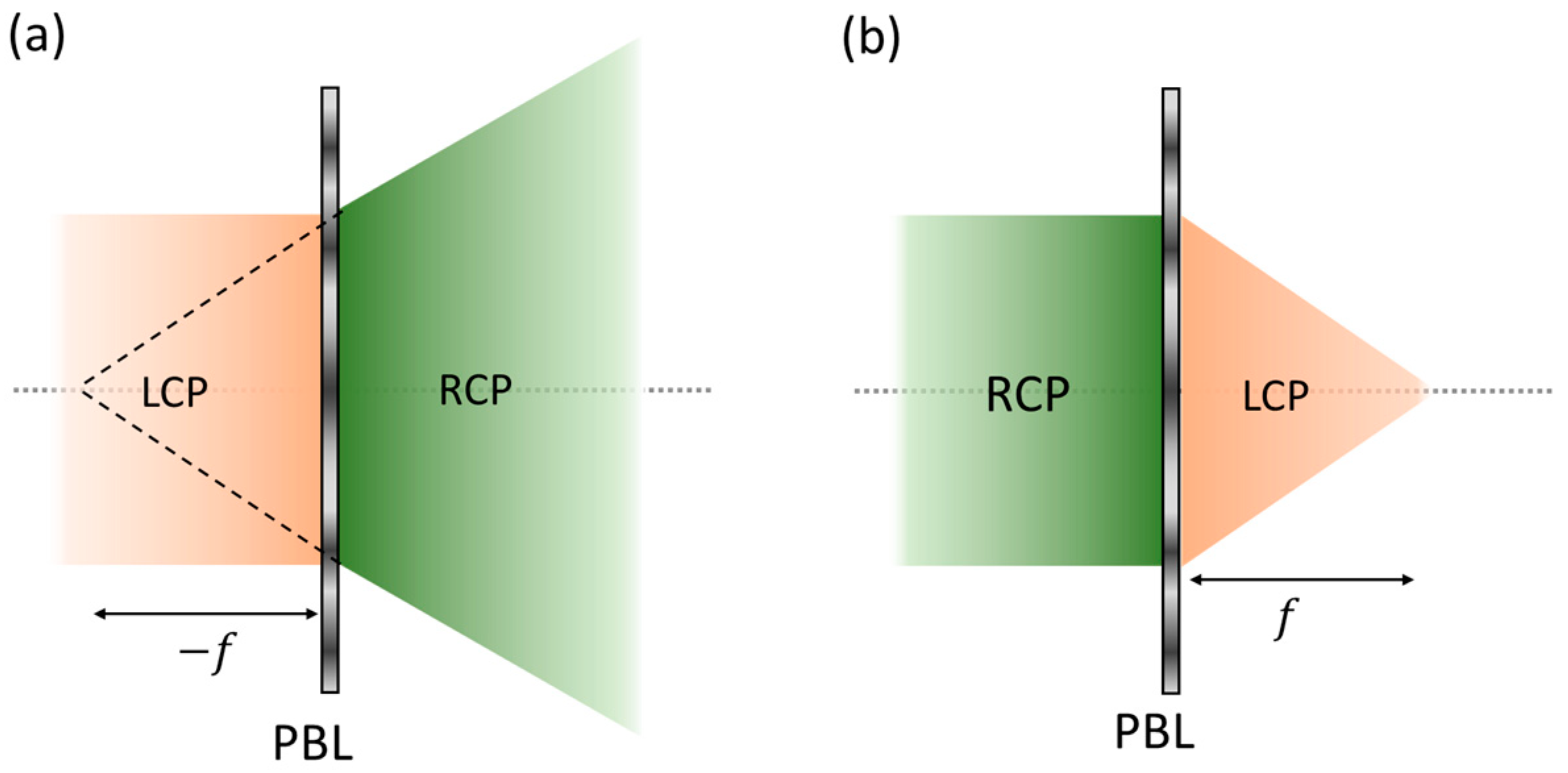
2.2. Pancharatnam–Berry Phase Lens

A Panchartnam–Berry phase optical element (PBOE) [28,29] is a patterned half-wave plate (HWP) with spatially varying optical axis orientations, e.g., different orientations of liquid crystal (LC) directors. More specifically, for an incident circularly polarized light (e.g., a right-handed circularly polarized (LCP) light), an HWP with an orientation angle φ can introduce a phase delay of 2 φ to the LCP light and convert it to a right-handed circularly polarized (RCP) light at the same time. If the incident light is an RCP light, then it will add a phase delay of 2 φ to the RCP light while converting it to an LCP light. This process can also be expressed using the Jones matrix representation as follows:
J ± = R φ H R φ 1 2 1 ± i = e ± i 2 φ 1 2 1 i   ,
where J ± and J ± are Jones vectors of input and output light, respectively, R corresponds to the rotation matrix and H represents the phase retardation matrix of HWP. Based on this working principle, if the spatial distribution of orientation angle φ x , y is a paraboloid function, then the PBOE is a Panchartnam–Berry phase lens (PBL). In addition, if the PBL is designed to function as a diverging lens for LCP, then it behaves as a converging lens for RCP, as depicted in Figure 4a,b, respectively.
Essentially, the PBL serves as a polarization-dependent bifocal lens. Using such a unique polarization response to LCP and RCP lights, we can achieve two different focal planes by implementing the polarization multiplexing method [30]. Specifically, by modulating the polarization of incident light using a switchable HWP and a quarter-wave plate (QWP), we can easily control the emergence of LCP to RCP and generate independent images for the two focal planes.

3. Proposed Method and Results

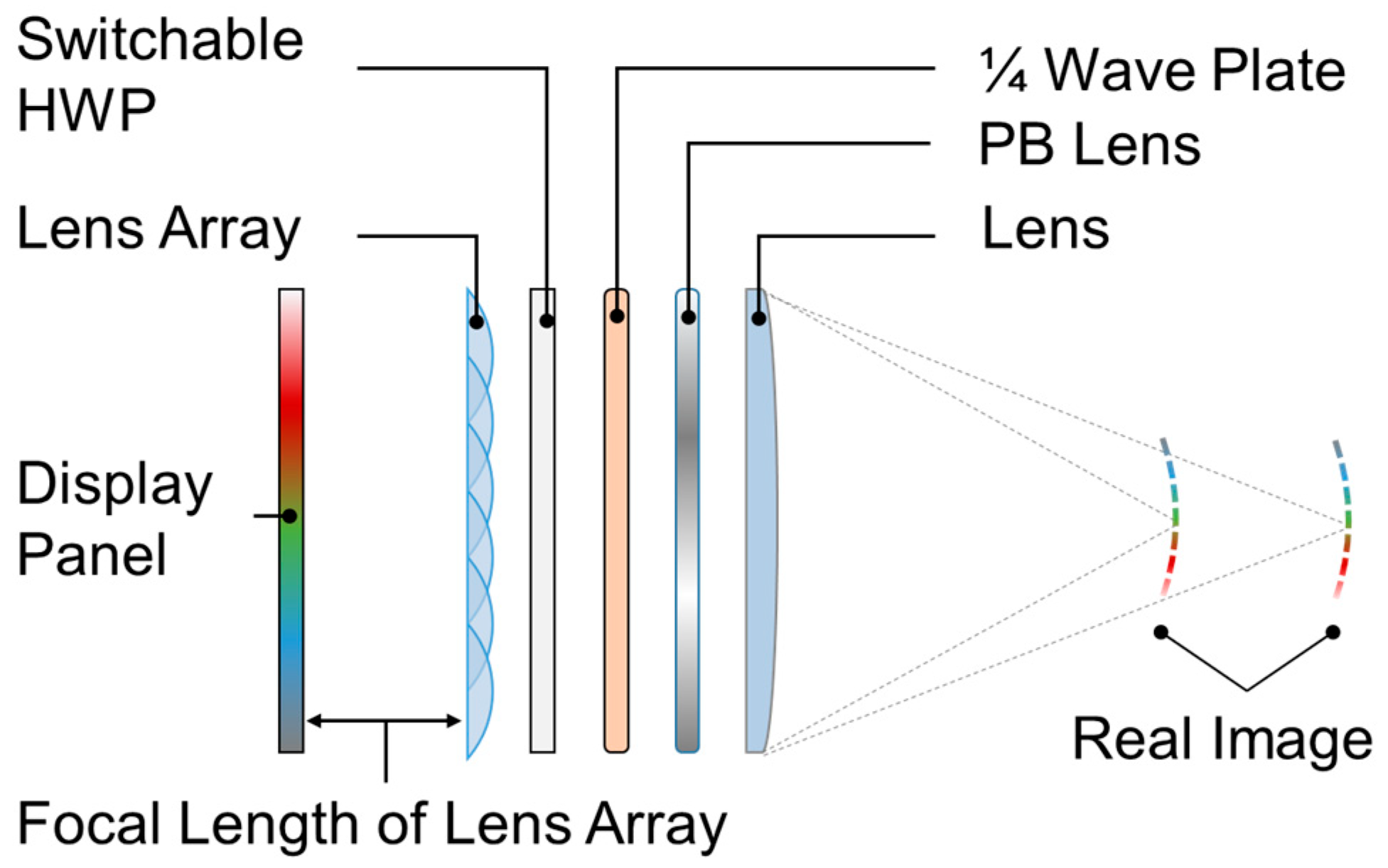
3.1. CIVI System with Time and Polarization Multiplexing

Figure 5 depicts the configuration of the proposed CIVI display with time and polarization multiplexing (TM and PM). The main components of the conventional CIVI system have remained the same, except for the number of display panels. An interleaved lens array is placed in front of a display panel with a high refresh rate. Since the distance between them is equal to the focal length of the lens array, parallel light rays are generated. We assume the polarization state of the light emitted from the display panel is linearly polarized along the z-axis (0°). Then, a switchable HWP, which modulates the light into the orthogonal polarization state (90°) or lets the light pass through itself without changes, is placed before the lens array. The light from two different linear polarization states is converted into RCP or LCP after passing through a broadband QWP oriented at 45°. These circularly polarized lights will converge at different positions, as depicted in Figure 5, by passing through the combination lens of a PBL and a standard convex lens whose power is larger than that of the PBL. When the high-speed alternation of the display panel and switchable HWP are synchronized, two different real images can be displayed and observed by the observer simultaneously.
Figure 6 illustrates the design of the right half of a single unit of interleaved lens with a width of 2.4 mm. Due to its symmetry, only the right half is depicted. Consequently, the total width of a single unit, which will be repeated to form a lens array, amounts to 4.8 mm. The orange prisms correspond to one elemental lens, while the blue prisms belong to the adjacent elemental lens. They are interleaved across the entire unit. Each unit consists of 20 prism pairs, where each pair consists of two prisms belonging to the elemental lens and its adjacent lens, with a width of 0.24 mm for each pair. The width of each prism varies depending on the distance from the center of each lens [17]. When multiple lens units are arranged as an array, it is equivalent to an overlapped cylindrical lens array. The elemental lens width is 9.6 mm, taking into account the overlap with the interleaved structure. The focal length of the lens is 15 mm.
We fabricated a metal mold according to this design and employed it for injecting plastics to produce the elemental lenses. PMMA (Polymethyl methacrylate) was chosen as the plastic material due to its minimal impact on light polarization. Two layers of the lens array were stacked orthogonally to create an interleaved convex lens array. Eight units were aligned horizontally, and four units were arranged vertically, which makes the size of the lens array 38.4 mm × 19.2 mm. The transition between view images can be seamlessly smoothed with the proposed lens array.

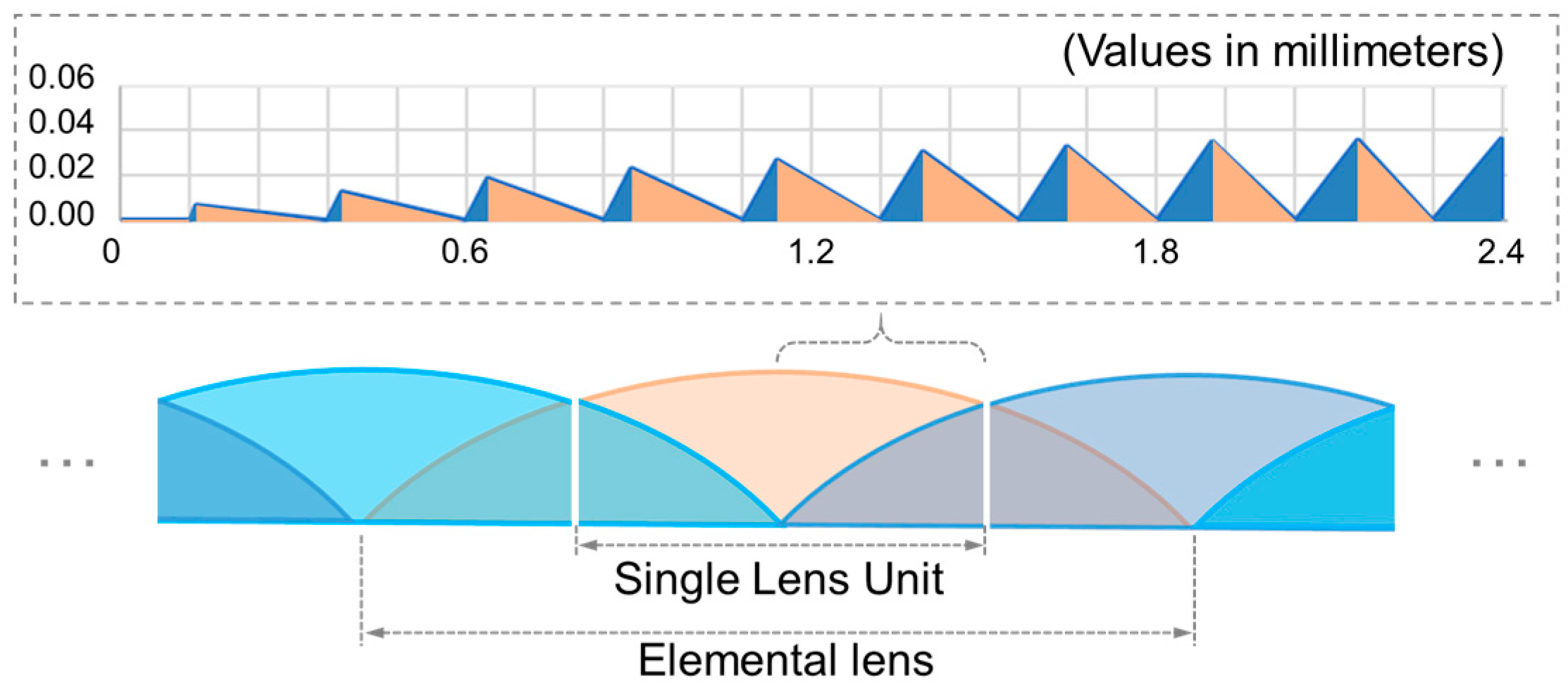
3.2. Fabrication of PBL

In experiments, a Mach–Zehnder Interferometer (MZI) is commonly employed to fabricate the PBL. To achieve the desired phase profile, the PBL is realized through interference exposure between RCP and LCP beams, each with a distinct phase pattern. The process can be described by the Jones matrix representation as follows:
J = 1 2 1 i e i α + 1 2 1 i e i β = cos α β 2 sin α β 2 e i α + β 2   .
Here, α and β corresponds to the phase pattern of RCP and LCP beams, respectively. As Equation (2) indicates, the recorded phase pattern is the phase difference between RCP and LCP beams. The orientation angle φ = α β / 2 is defined in Equation (2). After spin-coating an LC layer on the photoalignment material, the phase can be recovered when circularly polarized light traverses through the device.
Figure 7a illustrates the optical setup for the exposure process. A collimated laser beam (457 nm) is initially split into two beams by the first beam splitter (BS1). Subsequently, the two beams are converted to two orthogonal circular polarization states by QWP1 and QWP2, respectively. Different phase patterns from lens L1 and lens L2 are then carried by the two beams separately. Finally, the two beams are recombined and interfered on the sample by the second beam splitter (BS2).
As depicted in Figure 7b, there are basically five steps to fabricating the PBL. Initially, the photoalignment material, e.g., brilliant yellow (BY), was dissolved into a dimethyl-formamide (DMF) solution and spin-coated onto a glass substrate. Following this, the photoalignment material underwent exposure in the above MZI using a 457 nm laser, with the effective exposure focal length set at 1 m for a wavelength around 532 nm. After the exposure, reactive mesogen RM257 was employed to generate LC layers through spin-coating. Finally, the device is exposed to UV light for stabilization. To achieve a broadband spectrum for all the input RGB lights, a multi-twist structure [31] was used, as illustrated in Figure 7c. There are basically three LC layers. The incorporation of a chiral dopant in the LC mixture facilitates the formation of a helical structure within the first and third LC layers.

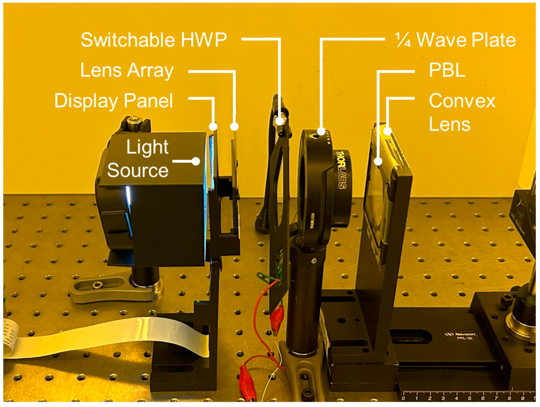
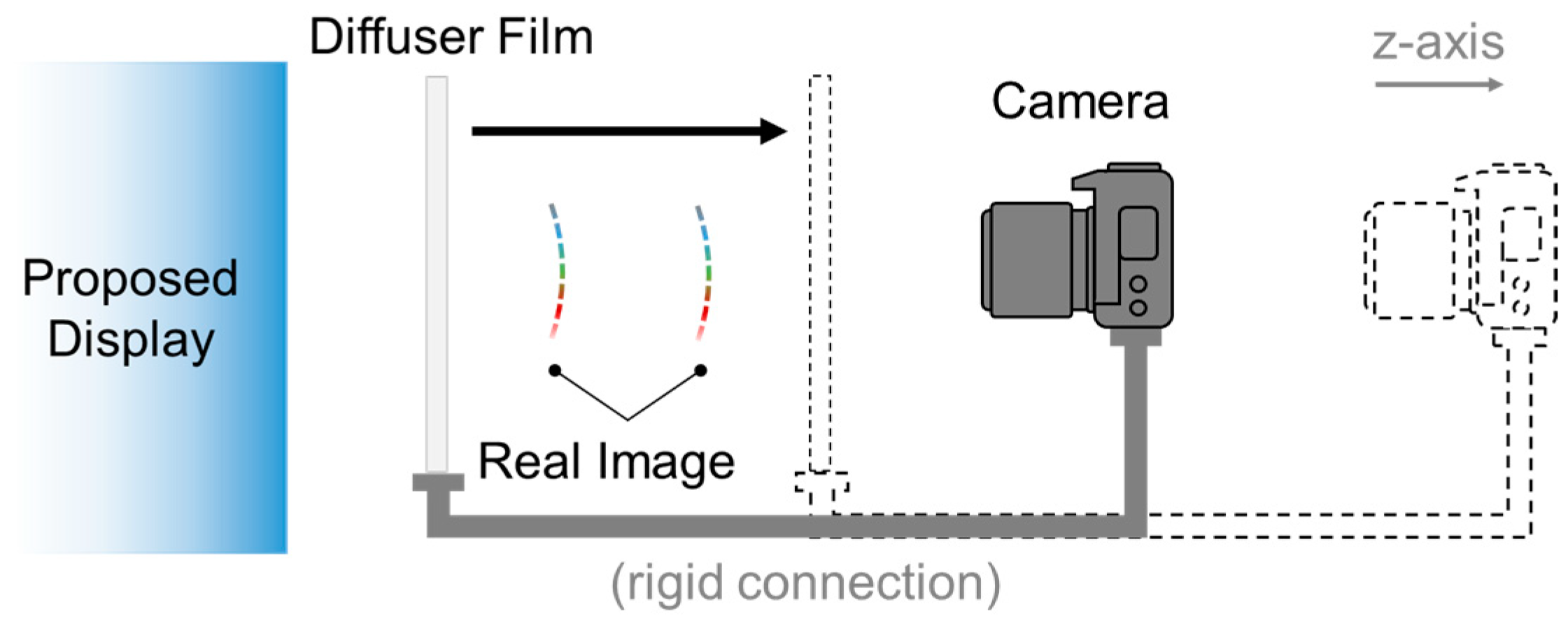
3.3. Breadboard Demonstration

Figure 8 illustrates the breadboard display systems, comprising a light-emitting diode (LED) light source, an LCD panel, a lens array, a switchable HWP, a QWP, a PBL, and an additional convex lens. Specifically, we utilized a portable 3.1-inch in-plane-switching (IPS) LCD panel (by Kyocera) with 800 × 480 resolution, 0.084 mm pixel pitch, and 120 Hz refresh rate as the display panel. An active shutter glass from NVIDIA 3D Vision 2 Wireless Glasses, designed to operate at a 120 Hz refresh rate, serves as the switchable HWP. The polarization films laminated to both sides of the glass panel were removed. The focal lengths of the PBL and the convex lenses were ±1000 mm and 100 mm, respectively. The equation for the two combined thin lenses is given by
1 f = 1 f 1 + 1 f 2 ,
hence, the two theoretical focal lengths are computed as 91 mm and 111 mm, irrespective of the lens thickness and the gap between the two lenses. The diameter of the PBL is 48 mm, which is slightly smaller than that of the convex lens. The horizontal viewing angle of the system can be given by
θ h = 2 arctan l h 2 f ,
where l h is the distance between the centers of two elemental lenses located on each edge of the lens array in the horizontal direction and f is the longer one of the two focal lengths. The vertical viewing angle θ v can also be calculated in the same way, and the results are θ h = 17.2 ° and θ v = 8.6 ° .
However, the slow response time of the IPS LCD introduces crosstalk between adjacent frames. The sample-and-hold nature of the active-matrix LCD results in persistent blurriness in the displayed images when showing a fast-moving object. This blurriness generates frames that mix the images intended for different depths. Simultaneously, the faster response time of the HWP leads to mixed images being reproduced at both focal planes. To address this issue, we implemented a four-time division with black frames inserted to alleviate crosstalk, although the tradeoff is a reduced frame rate (30 Hz).
To validate the generation of two focal planes at different depths, we conducted the experiment depicted in Figure 9. Photos of the real images projected on the diffuser screen were captured at 5 mm intervals, while the diffuser film and a camera, which were fixed at a distance of 400 mm, were shifted from the left to the right. Real images of a vertical line were produced to ascertain the location of the clearest real image along the z-axis. Although the actual system involves two dimensions, the one-dimensional (horizontal) experiment suffices for validation due to the system’s symmetry.
Three sets of photos were taken under three conditions: real image 1 generated without TM (first row), real image 2 generated without TM (second row), and both real images generated with TM (third row), as Figure 10 shows. Captured photos of the line on the diffuser screen exhibit reduced blurriness on specific occasions when the diffuser is positioned near the focal plane of the combined lens. Clear moments of real images 1 and 2 can be observed at different positions: approximately 90 mm and 110 mm. The camera parameters for the SONY ILCE-6100 are provided in Table 1. Considering the higher intensity of the white line compared to the green one, we adjusted the ISO value of the camera while capturing the latter.
To examine and visualize the convergence of light rays, we plotted the light intensities of the horizontal center lines of photos in Figure 10 at different z-axis positions (Figure 11). The horizontal coordinates in Figure 11 represent the lengths of each center line (unit: pixels) corresponding to the width of each elemental image in Figure 10. The intensity data for the experiment are derived from the gray levels of the photos, as the relative relationship between these levels is sufficient for finding the focal plane. As shown in Figure 11, converging points of light rays, represented by the thinnest and brightest parts, were identified at different positions, indicating the generation of two focal planes. We plotted the maximum intensities for each center line at different z-axis positions, as can be seen in Figure 12. The peaks of lines for images 1 and 2 appear within a distance of 10–15 mm, which is reduced to 5–15 mm when the TM is activated. Such a reduction is attributed to the activation of TM, which introduces additional crosstalk.
To achieve volumetric imaging, we employed the DFD method with two focal planes [25]. In the DFD approach, 3D pixels are represented using two adjacent panels, and each panel emits light inversely proportional to the distance between the 3D pixels and the panel itself, as illustrated in Figure 13a. Utilizing the DFD method, we computed the density of each pixel on the two image planes to generate volumetric stereoscopic images of a 3D model of a skull, as depicted in Figure 13b.
The breadboard successfully displays a 3D model of a skull with a complete parallax, and Figure 14 shows the photos captured from different viewing positions using the camera. The resolution of each elemental image is 60 × 60 pixels, constrained by the size of the elemental lenses in the lens array and the pixel pitch of the LCD panel. The parameters of the camera used in this observational experiment are shown in Table 2. As depicted in the figure, both the horizontal and vertical parallax are accurately reproduced as intended. Also, as expected, a moiré pattern does not emerge.

4. Discussion

The discrepancy between the calculated and actual distances between the two focal planes may be attributed to several factors. Firstly, the efficiency of the switchable HWP is lower than 100%, resulting in modulated light that is not purely at 0° or 90° polarization. This impurity affects the circularly polarized light just before passing through the PBL, making the expected focal plane susceptible to crosstalk from the light rays of the other focal plane and causing a deviation. Secondly, the efficiency of the PBL is also not 100%, leading to crosstalk between the generated focal plane and the original focal plane of the convex lens. Enabling TM exacerbates crosstalk issues due to the response time mismatch between the switchable HWP and the LCD panel. Reducing crosstalk among the two generated focal planes and the original focal plane of the convex lens will be the focus of future work, necessitating improvements in the efficiency of both the switchable HWP and the PBL.
In Figure 14, at the edges of some white images, there are isolated single colors separated from the white, which are believed to be caused by chromatic aberration in the combined lens. This chromatic aberration can be rectified through careful design of the combined lens [32] or pre-processing of the image contents. Additionally, the color dispersion of the PBL induced by diffraction can be further corrected or adjusted through a multilayer structure [33]. Low resolution is a contributing factor to the degraded image quality. This issue can be addressed by expanding the number of pixels covered by each elemental lens in the lens array. We will consider using an LCD panel with a smaller pixel pitch in the future.
The proposed display system exhibits a limited viewing angle due to the restricted aperture size of the PBL. Enhancing the viewing angle of the system is a key consideration for future work, primarily by enlarging the aperture size of the PBL. The size of the PBL depends on the size of the exposure beam applied to the sample. Fabricating a large-sized PBL with small lenses and mirrors necessitates longer exposure time, potentially introducing greater environmental instability and consequently reducing manufacturing yield.
The implementation of a four-time division with black frames reduces the frame rate to 30 Hz, reducing the smoothness and the brightness. When the four-time division multiplexing with black frames inserted is activated, the energy decreases to 25% or less. Utilizing a display panel with a smaller pixel pitch, a refresh rate exceeding 120 Hz, and a faster response time would facilitate the discarding of the four-time division and resuming the two-time division without black frames, achieving a 60 Hz refresh rate for 3D imaging. Additionally, energy loss can also be mitigated.
Furthermore, the integration of a switchable PBL [34], which introduces a pass-through state alongside the normal bifocal PBL, could expand the generated focal plane by the integral imaging optical system to three focal planes with a single LCD panel. Moreover, applying multiple PBLs or switchable PBLs could further increase the number of generated focal planes.

5. Conclusions

Traditional coarse integral volumetric imaging (CIVI) systems encounter the moiré problem arising from layered LCD panels. This paper presents a novel CIVI display employing time and polarization multiplexing techniques to showcase volumetric 3D images. Leveraging a Pancharatnam–Berry phase lens as a polarization-sensitive bifocal lens in our optical system allows us to achieve two focal planes using a single LCD panel. The use of a fine interleaved linear Fresnel lens array ensures a smooth transition between each view image.
The proposed method was demonstrated to be effective in reproducing real images with two focal depths, and multiple view images can be observed from various viewing positions. The newly designed experiment using a diffuser and a camera confirmed the successful generation of two focal planes, and the observation experiment further validated the presence of multiple view images.
There is increasing demand for contactless interactive stereoscopic displays to mitigate the risk of pathogen transmission through physical contact. The suggested real-image-type bifocal CIVI offers a promising solution for interactive 3D displays that can reproduce spatial images for viewer interaction. The integration of ultrasound mid-air haptic systems [35] with CIVI systems is anticipated to bring about the realization of these 3D displays. A completely new interactive experience is made possible by superimposing tactile sensations onto the floating images. Furthermore, virtual-image-type bifocal CIVI represents a potential solution for achieving a near-eye super-multi-view light field display, offering a means to alleviate the effects of vergence-accommodation conflicts.

Author Contributions

Conceptualization, G.B. and H.K.; fabrication of PBL, Y.D., J.S., H.T.S., and G.B.; experiment, G.B. and Y.D.; design of lens array, H.K.; writing—original draft preparation, G.B. and Y.D.; writing—review and editing, H.K. and S.-T.W. All authors have read and agreed to the published version of the manuscript.

Funding

This research was funded by the Japan Society for the Promotion of Science, grant numbers JP22H03624, JP22J10941, and JP22KJ0396 and Core Research for Evolutional Science and Technology, grant number JPMJCR18A2.

Institutional Review Board Statement

Not applicable.

Informed Consent Statement

Not applicable.

Data Availability Statement

Data underlying the results presented in this paper are not publicly available at this time but may be obtained from the authors upon reasonable request.

Acknowledgments

We would like to extend our sincere appreciation to Hirotsugu Yamamoto from Utsunomiya University for his invaluable and insightful advice on the experimental aspects of integral imaging systems.

Conflicts of Interest

The authors declare no conflict of interests.

References

  1. Lippman, G. La Photographie Integrale. Comptes-Rendus 1908, 146, 446–451. [Google Scholar]
  2. Burckhardt, C.B. Optimum Parameters and Resolution Limitation of Integral Photography. JOSA 1968, 58, 71–76. [Google Scholar] [CrossRef]
  3. Okoshi, T. Three-Dimensional Displays. Proc. IEEE 1980, 68, 548–564. [Google Scholar] [CrossRef]
  4. Arimoto, H.; Javidi, B. Integral Three-Dimensional Imaging with Digital Reconstruction. Opt. Lett. 2001, 26, 157–159. [Google Scholar] [CrossRef] [PubMed]
  5. Jang, J.-S.; Javidi, B. Large Depth-of-Focus Time-Multiplexed Three-Dimensional Integral Imaging by Use of Lenslets with Nonuniform Focal Lengths and Aperture Sizes. Opt. Lett. 2003, 28, 1924–1926. [Google Scholar] [CrossRef] [PubMed]
  6. Deng, H.; Wang, Q.-H.; Li, D.-H.; Wang, F.-N. P-1: An Integral Imaging Display With Wide Viewing Angle. SID Symp. Dig. Tech. Pap. 2011, 42, 1095–1097. [Google Scholar] [CrossRef]
  7. Lee, B.; Jung, S.; Min, S.-W.; Park, J.-H. Three-Dimensional Display by Use of Integral Photography with Dynamically Variable Image Planes. Opt. Lett. 2001, 26, 1481–1482. [Google Scholar] [CrossRef]
  8. Lee, B.; Jung, S.; Park, J.-H.; Min, S.-W. Viewing-Angle-Enhanced Integral Imaging Using Lens Switching. In Proceedings of the Stereoscopic Displays and Virtual Reality Systems IX (SPIE), San Jose, CA, USA, 23 May 2002; Volume 4660, pp. 146–154. [Google Scholar]
  9. Park, J.-H.; Jung, S.; Choi, H.; Lee, B. Integral Imaging with Multiple Image Planes Using a Uniaxial Crystal Plate. Opt. Express 2003, 11, 1862–1875. [Google Scholar] [CrossRef]
  10. Min, S.-W.; Javidi, B.; Lee, B. Enhanced Three-Dimensional Integral Imaging System by Use of Double Display Devices. Appl. Opt. 2003, 42, 4186–4195. [Google Scholar] [CrossRef]
  11. Min, S.-W.; Hahn, M.; Kim, J.; Lee, B. Three-Dimensional Electro-Floating Display System Using an Integral Imaging Method. Opt. Express 2005, 13, 4358–4369. [Google Scholar] [CrossRef]
  12. Kim, Y.; Park, J.-H.; Choi, H.; Kim, J.; Cho, S.-W.; Lee, B. Depth-Enhanced Three-Dimensional Integral Imaging by Use of Multilayered Display Devices. Appl. Opt. 2006, 45, 4334–4343. [Google Scholar] [CrossRef] [PubMed]
  13. Kim, Y.; Choi, H.; Kim, J.; Cho, S.-W.; Kim, Y.; Park, G.; Lee, B. Depth-Enhanced Integral Imaging Display System with Electrically Variable Image Planes Using Polymer-Dispersed Liquid-Crystal Layers. Appl. Opt. 2007, 46, 3766–3773. [Google Scholar] [CrossRef] [PubMed]
  14. Kakeya, H. Formulation of Coarse Integral Imaging and Its Applications. In Proceedings of the Stereoscopic Displays and Applications XIX (SPIE), San Jose, CA, USA, 29 February 2008; Volume 6803, pp. 412–421. [Google Scholar]
  15. Kakeya, H.; Sawada, S.; Ueda, Y.; Kurokawa, T. Integral Volumetric Imaging with Dual Layer Fly-Eye Lenses. Opt. Express 2012, 20, 1963–1968. [Google Scholar] [CrossRef] [PubMed]
  16. Kakeya, H.; Sawada, S. Reduction of Image Discontinuity in Coarse Integral Volumetric Imaging. Opt. Lett. 2015, 40, 5698–5701. [Google Scholar] [CrossRef] [PubMed]
  17. Borjigin, G.; Kakeya, H. Backlight System Using an Interleaved Fresnel Lens Array That Attains a Uniform Luminance and Two-Dimensional Directional Light Control. Opt. Lett. 2022, 47, 301–304. [Google Scholar] [CrossRef] [PubMed]
  18. Chen, X.; He, Y.; Li, X.; Cheng, M.; Li, Z.; Deng, D.; Wang, S.; Liang, H.; Li, K.; Zhou, J. Harnessing and Cloaking Optical Boundary in Lens-Array Based Display. Opt. Lasers Eng. 2022, 156, 107085. [Google Scholar] [CrossRef]
  19. Kim, Y.; Park, G.; Jung, J.-H.; Kim, J.; Lee, B. Color Moiré Pattern Simulation and Analysis in Three-Dimensional Integral Imaging for Finding the Moiré-Reduced Tilted Angle of a Lens Array. Appl. Opt. 2009, 48, 2178–2187. [Google Scholar] [CrossRef] [PubMed]
  20. Wang, L.; Deng, H.; Zhong, F.-Y.; Chen, C.; Li, Q. Integral Imaging Display with Enhanced Depth of Field Based on Bifocal Lens Array. J. Soc. Inf. Disp. 2021, 29, 689–696. [Google Scholar] [CrossRef]
  21. Park, M.; Choi, H.-J. A Method to Enhance the Depth Range of an Integral Imaging System Using a Geometric Phase Lens. In Proceedings of the Digital Holography and Three-Dimensional Imaging 2018, Orlando, FL, USA, 25–28 June 2018. [Google Scholar]
  22. Shen, X.; Wang, Y.-J.; Chen, H.-S.; Xiao, X.; Lin, Y.-H.; Javidi, B. Extended Depth-of-Focus 3D Micro Integral Imaging Display Using a Bifocal Liquid Crystal Lens. Opt. Lett. 2015, 40, 538–541. [Google Scholar] [CrossRef]
  23. Wang, Q.-H.; Ji, C.-C.; Li, L.; Deng, H. Dual-View Integral Imaging 3D Display by Using Orthogonal Polarizer Array and Polarization Switcher. Opt. Express 2016, 24, 9–16. [Google Scholar] [CrossRef]
  24. Kwon, K.-C.; Erdenebat, M.-U.; Lim, Y.-T.; Joo, K.-I.; Park, M.-K.; Park, H.; Jeong, J.-R.; Kim, H.-R.; Kim, N. Enhancement of the Depth-of-Field of Integral Imaging Microscope by Using Switchable Bifocal Liquid-Crystalline Polymer Micro Lens Array. Opt. Express 2017, 25, 30503–30512. [Google Scholar] [CrossRef] [PubMed]
  25. Suyama, S.; Takada, H.; Uehira, K.; Sakai, S.; Ohtsuka, S. 54.1: A Novel Direct-Vision 3-D Display Using Luminance-Modulated Two 2-D Images Displayed at Different Depths. SID Symp. Dig. Tech. Pap. 2000, 31, 1208–1211. [Google Scholar] [CrossRef]
  26. Suyama, S.; Takada, H.; Ohtsuka, S. A Direct-Vision 3-D Display Using a New Depth-Fusing Perceptual Phenomenon in 2-D Displays with Different Depths. IEICE Trans. Electron. 2002, E85-C, 1911–1915. [Google Scholar] [CrossRef] [PubMed]
  27. Suyama, S.; Ohtsuka, S.; Takada, H.; Uehira, K.; Sakai, S. Apparent 3-D Image Perceived from Luminance-Modulated Two 2-D Images Displayed at Different Depths. Vision Res. 2004, 44, 785–793. [Google Scholar] [CrossRef] [PubMed]
  28. Pancharatnam, S. Generalized Theory of Interference, and Its Applications. Proc. Indian Acad. Sci. Sect. A 1956, 44, 247–262. [Google Scholar] [CrossRef]
  29. Berry, M.V. Quantal Phase Factors Accompanying Adiabatic Changes. Proc. R. Soc. Lond. Math. Phys. Sci. 1997, 392, 45–57. [Google Scholar]
  30. Tan, G.; Zhan, T.; Lee, Y.-H.; Xiong, J.; Wu, S.-T. Polarization-Multiplexed Multiplane Display. Opt. Lett. 2018, 43, 5651–5654. [Google Scholar] [CrossRef]
  31. Zou, J.; Zhan, T.; Xiong, J.; Wu, S.-T. Broadband Wide-View Pancharatnam–Berry Phase Deflector. Opt. Express 2020, 28, 4921–4927. [Google Scholar] [CrossRef]
  32. Zhan, T.; Zou, J.; Xiong, J.; Liu, X.; Chen, H.; Yang, J.; Liu, S.; Dong, Y.; Wu, S.-T. Practical Chromatic Aberration Correction in Virtual Reality Displays Enabled by Cost-Effective Ultra-Broadband Liquid Crystal Polymer Lenses. Adv. Opt. Mater. 2020, 8, 1901360. [Google Scholar] [CrossRef]
  33. Luo, Z.; Li, Y.; Semmen, J.; Rao, Y.; Wu, S.-T. Achromatic Diffractive Liquid-Crystal Optics for Virtual Reality Displays. Light Sci. Appl. 2023, 12, 230. [Google Scholar] [CrossRef]
  34. Zhan, T.; Lee, Y.-H.; Wu, S.-T. High-Resolution Additive Light Field near-Eye Display by Switchable Pancharatnam–Berry Phase Lenses. Opt. Express 2018, 26, 4863–4872. [Google Scholar] [CrossRef] [PubMed]
  35. Monnai, Y.; Hasegawa, K.; Fujiwara, M.; Yoshino, K.; Inoue, S.; Shinoda, H. HaptoMime: Mid-Air Haptic Interaction with a Floating Virtual Screen. In Proceedings of the 27th Annual ACM Symposium on User Interface Software and Technology, New York, NY, USA, 5 October 2014; pp. 663–667. [Google Scholar]
Figure 1. Principle of coarse integral imaging (CII).
Photonics 11 00007 g001
Figure 2. Principle of coarse integral volumetric imaging (CIVI). [Redrawn from [15]].
Photonics 11 00007 g002
Figure 3. (a) Elemental lenses with interleaved grooves in the connecting part. (b) Elemental lenses with interleaved grooves across the entire lens.
Photonics 11 00007 g003
Figure 4. Working principle of PBL: (a) response to an LCP incident light and (b) response to an RCP incident light.
Photonics 11 00007 g004
Figure 5. Device configuration of the proposed CIVI display system.
Photonics 11 00007 g005
Figure 6. Design of the interleaved lenses composing the lens array used in the prototype system (a cross section of the right half of a single lens unit is shown above).
Photonics 11 00007 g006
Figure 7. Fabrication process: (a) exposure setup for PBL fabrication, (b) flowchart of PBL fabrication procedures, and (c) the multi-twist structure of the broadband PBL.
Photonics 11 00007 g007
Figure 8. The breadboard system based on the proposed method.
Photonics 11 00007 g008
Figure 9. Experimental setup for capturing real images.
Photonics 11 00007 g009
Figure 10. Photos of real images showing (a) the green line and (b) the white line.
Photonics 11 00007 g010
Figure 11. Horizontal center line light intensities in photos of (a) green lines and (b) white lines at different z-axis positions. The vertical color bars represent the light intensity.
Photonics 11 00007 g011
Figure 12. Maximum values of intensities for each horizontal center line at different z-axis positions. Plots of (a) the green line and (b) the white line.
Photonics 11 00007 g012
Figure 13. (a) Principle of DFD. (b) An example of real images.
Photonics 11 00007 g013
Figure 14. Images generated by the proposed CIVI observed from different viewing positions: (af) white images; (gl) green images; and images observed from (a,g) upper-left, (b,h) upper-center, (c,i) upper-right, (d,j) lower-left, (e,k) lower-center, and (f,l) lower-right viewpoints.
Photonics 11 00007 g014
Table 1. Camera parameters for the experiment capturing real images.
Camera ParameterGreen Line (TM Off)Green Line (TM On)White Line (TM Off)White Line (TM On)
f/numberf/22f/22f/22f/22
ISO value20,00020,00010,00010,000
Shutter speed1/51/51/51/5
Table 2. Camera parameters used to capture displayed images from different positions.
Camera ParameterWhite ImageGreen Image
f/numberf/22f/22
ISO value25006400
Shutter speed1/101/10
Disclaimer/Publisher’s Note: The statements, opinions and data contained in all publications are solely those of the individual author(s) and contributor(s) and not of MDPI and/or the editor(s). MDPI and/or the editor(s) disclaim responsibility for any injury to people or property resulting from any ideas, methods, instructions or products referred to in the content.

