Abstract
In this work, a vertical N-I-P germanium (Ge) photodetector (PD) with a multi-mode waveguide input is presented. The fabricated devices exhibit a low dark current of 10 nA at bias of −1 V, and a high responsivity of exceeding 0.75 A/W over the wavelength range from 1270 to 1350 nm. High-frequency characteristics measurements show that the photodetector has a 3 dB opto-electrical (OE) bandwidth of 23 GHz under −3 V bias, which can be further improved by optimization of the photodetector configuration. A 50 Gb/s clear eye diagram with a non-return-to-zero (NRZ) modulation format is demonstrated. By using a single-mode excitation source, which is used to simulate light coming from the wavelength division multiplexing (WDM) devices, and sweeping its position, it is shown that the multi-mode input photodetector can be utilized in a WDM receiver to achieve both high responsivity and a flat-top passband.
1. Introduction
With the rapid development of Internet services such as big data and cloud computing, data centers and communication networks are increasingly demanding high-speed optical interconnects [1,2,3]. Among them, silicon photonics (SiPh) is one of the most promising technologies due to its compatibility with the mature Complementary Metal Oxide Semiconductor (CMOS) processes to achieve large-scale integration at a lower cost [4,5,6]. Photodetectors (PDs) are essential components that convert optical signals to electrical signals [7,8,9]. An ideal PD should have the characteristics of low dark current, high quantum efficiency, and high OE bandwidth. Group IV materials are suitable for application in photodetection, and many performance devices have been demonstrated [10]. The indirect band-gap structure of the Si material with 1.1 eV band-gap energy, makes it suffer from low quantum efficiency at the 1.3–1.55 m communication wavelength, while Ge has a large absorption coefficient up to 2 m, and has been widely used in CMOS fabrication processes for high-responsivity and high-bandwidth Ge-on-Si photodetectors [11,12,13,14,15,16,17]. In [18], the detector’s bandwidth was increased to 60 GHz by using two different inductors to achieve gain peaking. In [15], a lateral P-I-N (L-PIN) detector with a high responsivity of 0.92 A/W and an OE greater than 67 GHz was demonstrated by growing Ge material on the recess of the Si material and removing metal contacts on Ge to Si. This process significantly enhances the responsivity by reducing light absorption from metal contacts, which contributes to substantial responsivity loss. Recently, the bandwidth of the L-PIN detector was boosted to a record-breaking 265 GHz [19] by improving the processing technology, using in situ doped silicon layers as P-type and N-type regions, and inserting a very thin double-concave germanium absorbing layer between them.
WDM technology is a fundamental technology in optical communication, which enables the transmission of multiple information signals at different wavelengths, thus expanding communication capacity [20]. On-chip WDM devices commonly used in the field include arrayed waveguide gratings (AWGs) [21,22], echelle gratings [23,24], and Mach–Zehnder cascaded lattice filters [25,26]. However, the small optical bandwidth of these devices makes them vulnerable to the effects of the fabrication process and temperature, requiring the use of complex temperature control systems. The use of multi-mode waveguide output can provide a flat passband and effectively solve this issue, and such WDM devices with multi-mode waveguide output are called MM-WDMs. Nevertheless, it is crucial to effectively receive all the multi-mode beams at the photodetector facet, as the light output from the multi-mode waveguide consists of both the fundamental mode and higher-order modes. Direct transmission of multi-mode light to the photodetector array through a single-mode waveguide would result in significant losses, leading to low responsivity. To address this, Yoshiyuki Doi et al. installed a large area surface-illuminated photodetector at the output facet of the multi-mode AWG, achieving an 8-channel multi-wavelength optical receiver with a responsivity of 0.8 A/W. However, the single-channel transmission rate was limited to 1.25 Gb/s [27] due to the photodetector’s large area. To reduce the photodetector area, the group added a grated-index micro-lens array between the multi-mode AWG and the detector array, which improved the data rate to 4 × 25 Gb/s and enabled a responsivity of 0.7 A/W through optical sub-assembling [28]. However, full integration is very beneficial, ref. [29] as integrating the WDMs and PD array together can reduce packaging steps, improve yield, and lower costs, and it is even a must for the integration of more channels such as 8 and 16, which is important for a co-packaged optics (CPO) system to conserve fiber resources. Therefore, it is necessary to verify the feasibility of directly using multi-mode waveguides to connect waveguide-type PDs and MM-WDMs, which is more convenient and cost-effective.
In this paper, the structure of the multi-mode waveguide input photodetector is first introduced. The use of a multi-mode waveguide preserves high-order modes from the output end of the MM-WDMs, ensuring the complete transmission of light to the detector. Then, the dark current and responsivity of the PD used in the experiment are measured. Finally, the OE bandwidth measurements are executed under different biases. Furthermore, the eye diagram measurements of NRZ modulation formats are also performed.
2. Materials and Methods
In photonics-integrated circuits, the input of a typical Ge photodetector (T-PD) is a single-mode silicon waveguide, and the optical transport between the input waveguide and PD is connected through a tapered silicon waveguide as shown in Figure 1a. To mimic the high-order mode waveguide at the output of the WDM devices, a multi-mode waveguide is used as the input of the PD in our experiment as shown in Figure 1b. Furthermore, in this paper, this type of photodetector is named a multi-mode photodetector (MM-PD).

Figure 1.
Schematic: (a) Typical photodetector (T-PD) with a single-mode waveguide input. (b) Multi-mode input photodetector (MM-PD), and the single-mode waveguide is the excitation source.
Since the performance of the MM-WDMs is related to the number of modes that can be accommodated in the waveguide at the output [30], the effective refractive indexes of the first 10 modes in the waveguide as a function of the waveguide width are calculated using Finite Different Eigenmode solver in Lumerical software [31]. The results, shown in Figure 2a, and the mode profile of these modes in a waveguide with 4 m width that are shown in Figure 2b, indicate that the first 10 modes in the waveguide are very excited when the waveguide width is 4 m. Thus, a waveguide width of 4 m is chosen for the multi-mode waveguide in this study.
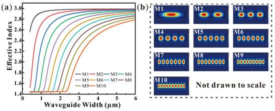
Figure 2.
(a) Effective index of the first 10 modes in waveguide versus waveguide width. (b) Mode profiles of the first 10 modes in a waveguide with 4 m width.
For MM-WDMs, each wavelength of light arrives at a different position in the output waveguide. Therefore, compared to single-mode waveguides, wider output waveguides can accommodate more wavelengths of light, which is also the reason why MM-WDMs have a flattened transmission spectrum. In the case of the MM-PD, this arrival is simulated by controlling the Y-position of a single-mode waveguide that serves as the excitation source, as shown in Figure 1b.
The MM-PDs were fabricated in an 8-inch commercial CMOS fab with developed SiPh processes. An 8-inch silicon-on-insulator (SOI) wafer with a 220 nm thick device layer and a 2 m thick buried oxide layer is used as starting material. The Ge waveguide photodetector used in the experiment has a vertical N(Ge)-I-P(Si) (V-NIP) architecture. The PD has a length of 20 m, a Ge waveguide width of 4 m, and a height of 500 nm, as shown in the cross-sectional structure in Figure 3a. A scanning electron microscope (SEM) photo of the fabricated device is presented in Figure 3b. The Ge waveguide has a thickness of 612 nm and a bottom width 4.4 m. The detailed fabrication process flow of the Ge V-PIN photodetector is shown in Figure 4.
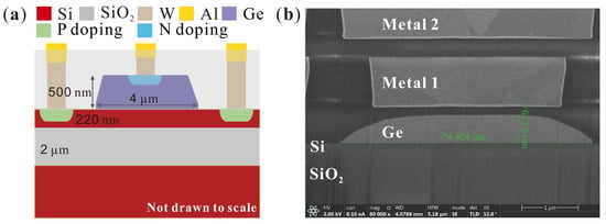
Figure 3.
(a) Cross-section schematic of the fabricated vertical N(Ge)-I-P(Si) photodetector. (b) Scanning Electron Microscope (SEM) photo of the fabricated device.
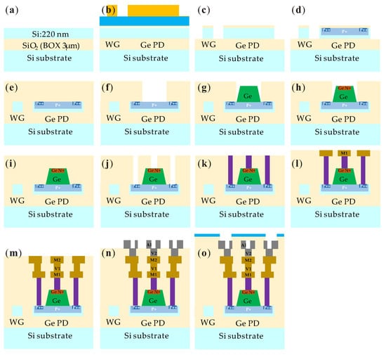
Figure 4.
The schematic of the fabrication process flow for the waveguide and Ge PD. (a) Prepare the starting SOI wafer, which has a 2 m thick layer of BOX (Buried) on a Si substrate and a 220 nm thick layer of top silicon. (b) Si WG definition is performed by a nitride hard mask, which is deposited on top of the Si layer and patterned using lithography. (c) Si layer is etched and the hard mask is removed after resist stripping. (d) Base implants (P+, P++) are introduced on the Si layer for the photodetector. (e) Oxide filling and chemical mechanical polishing (CMP). (f) Ge PD windows opening. (g) The Ge layer is selectively grown by epitaxy. (h) N implant on Ge. (i) Oxide filling and CMP. (j) Opening windows for contacts on Si and Ge. (k) Tungsten (W) is filled and CMP is performed to format contact on both Si and Ge. (l) Metal 1 (M1) formation using the damascene process. (m) Via 1 (V1) and Metal 2 (M2) formation using the damascene process. (n) Via 2 (V2) and Pad aluminum (Al) are formed to provide electrical connections. (o) A nitride passivation layer is deposited to protect the device from external contaminants, and the passivation layer is then patterned using lithography to expose the necessary contact pads and openings for electrical connections.
3. Results
As a reference, a T-PD with a single-mode waveguide input was also fabricated. The experimental results are compared between the T-PD and MM-PD in the subsequent paper.
3.1. Dark Current
The dark current measurements of the PD were conducted at room temperature using Keysight B2902 high-precision source meters. Figure 5a shows the typical I–V characteristic curve of the PD, which was measured at a bias voltage ranging from −3 V to 1.5 V. The device has a low dark current of about 10 nA at the bias of −1 V, and less than 50 nA at the bias of −3 V. In addition, the dark currents of 60 identical devices were measured at different biases and are presented using boxplots in Figure 5b. The devices were fabricated on five different slices labeled as C03, C06, E04, F06, and G03. Each slice contained 12 devices that are distinguished by different colors in the figure. Without some outliers, the distribution of the dark current is concentrated, indicating the uniformity of the fabrication.
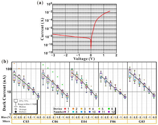
Figure 5.
(a) I–V curve of the photodetector plotted on a logarithmic scale for the y-axis. The dark current at −1 V and −3 V is around 10 nA and 50 nA, respectively. (b) The boxplot of the dark currents of 60 identical devices at different biases are presented, where the devices were fabricated on 5 different slices labeled as C03, C06, E04, F06, and G03. Each slice contained 12 devices, represented by different colors in the figure.
3.2. Responsivity
The responsivity experiments were carried out based on Figure 6. Firstly, the loss A of the system link was measured. The light was from a Keysight 81608A O band tunable laser (TLS), with the polarization adjusted to TE polarization using a Keysight N7786B polarization controller, then passed through the left stage on the alignment platform to the right stage. To eliminate any reflection from the interface of the two single-mode fibers, a matching oil was used. The optical power was measured using a Keysight N7744A optical power meter. Secondly, two grating couplers and a short waveguide with a length of less than 1 mm were measured. The total loss is marked as B, and since the waveguide loss is negligible, the loss of a single grating coupler can be calculated by (B − A)/2. In the third step, a Thorlabs SM05PD5A surface-illuminated photodetector was used for calibration. The optical power C that reaches the surface of the grating coupler can be calculated by using the measured optical current and responsivity of the calibration photodetector. Finally, the optical current D of the fabricated devices was measured. The responsivity of the photodetectors can then be calculated using the formula R = D/(C − (B − A)/2).
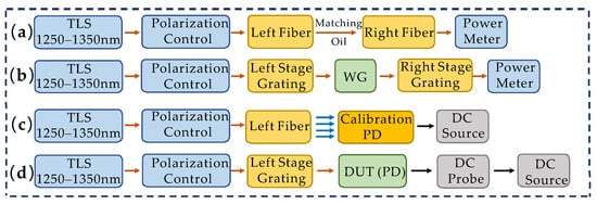
Figure 6.
Experimental setup for the responsivity measurements. (a) Loss of system link. (b) Loss measurement of a single grating coupler. (c) Calculation of the optical power that reaches the surface of the grating coupler. (d) The optical current measurement of the PD.
The measured transmission spectrum of the grating from 1250 to 1350 nm is presented in Figure 7a. The grating has a limited 1 dB bandwidth of approximately 30 nm. The insertion loss of the grating is −4.6 dB at 1310 nm and decreases to −21 dB at 1250 nm. The apparent ripples at short and long wavelengths in the spectrum originate from interference between incident light and reflected light at the grating surface. The high loss and strong reflection at short wavelengths have a great impact on the accuracy of the measurement results. Figure 7b shows the responsivity spectrum of the MM-PD at different biases ranging from 1270 to 1350 nm. It was determined that the reverse bias has no effect on responsivity, as the built-in electric field is strong enough to efficiently transport photo-generated carriers to the contacts. The long-period ripple observed in Figure 7b is caused by interference between different orders of optical fields inside the silicon as they couple from silicon waveguide to germanium waveguide. The responsivity of the MM-PD at 1310 nm is around 0.8 A/W, and it ranges from 0.8 to 0.9 A/W over the entire wavelength range. As a reference, the responsivity of the T-PD was also measured. As shown in Figure 7c, the response spectrum of the T-PD is comparable to the MM-PD, and the peaks of the ripples are located at the same wavelength as Figure 7b, providing further evidence that the ripples are not due to multi-mode input. The ripples in Figure 7c exhibit the same characteristics as those in Figure 7b, indicating that the cause of the ripples in both figures is the same.
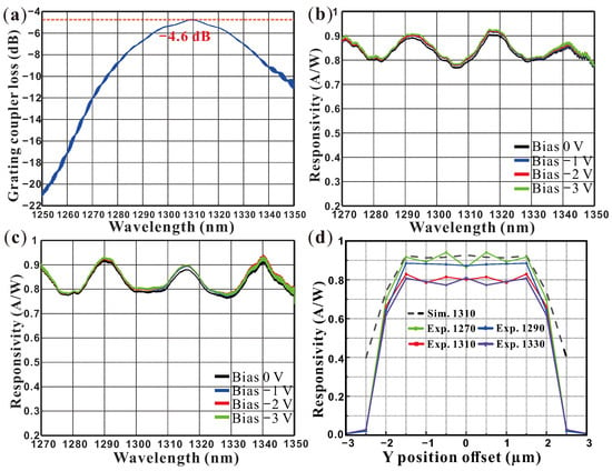
Figure 7.
(a) Loss of grating coupler from 1250 to 1350 nm. Responsivity spectrum of the MM-PD (b) and T-PD (c) from 1270 to 1350 nm at different biases. (d) Responsivity for different Y-position offsets of the excitation source: the dashed line is the simulated result at 1310 nm, and the green, blue, red, and purple solid lines are the experimental results, respectively.
To simulate the light at different wavelengths from various positions at the MM-WDMs, the Y position of a single-mode waveguide, as shown in Figure 1b, was varied. The light absorption was obtained using the Finite Different Time Domain solver and responsivity was calculated with the Charge Transport solver in Lumerical software. As demonstrated by the dashed black line in Figure 7d, the simulated responsivity of MM-PD at 1310 nm is near 1 A/W when the source input waveguide overlaps with the multi-mode waveguide but drops rapidly when the two waveguides stray from each other. The experimental results for 1270 nm, 1290 nm, 1310 nm, and 1330 nm wavelength laser inputs are displayed as solid green, blue, red, and purple lines in Figure 7d, respectively. The overall trend of simulation and experiment coincides well with the responsivity of the MM-PD at 1310 nm beyond 0.75 A/W in the whole width range (±2 m) of the multi-mode wave-guide, indicating that the MM-PD can be utilized to form a receiver with a flat transmission spectrum. The measured response is lower than the simulated one because light entering the photodetector is not completely absorbed, and this can be resolved by increasing the device length.
3.3. Opto-Electrical Bandwidth
The OE bandwidth of a photodetector is determined by two factors: the RC time constant in the circuit and the transit time for the photo-generated carriers to travel to the electrodes. For the former, reducing the contact resistance and the resistance in the Si slab region is a feasible approach. For the latter, increasing the electric field strength in the Ge waveguide can accelerate the carrier migration velocity, especially in the weak electric field at the corners of the Ge waveguide. The radio frequency characteristics measurements of the photodetectors were performed based on Figure 8a. A modulated optical signal from a Keysight N4373E vector network analyzer (VNA), with the polarization adjusted to TE polarization using a Keysight N7786B polarization controller, passed into the photodetector through a grating coupler. The photodetector was biased using a Keysight B2902A and a 50 GHz GSG RF probe connected to a 40 GHz bias tee. The photocurrent output was then measured using the VNA. The normalized frequency response of the device is shown in Figure 8b. At a bias voltage of −3 V, the device achieves a bandwidth of 23 GHz, which is similar to that of the T-PD. The low bandwidth of the photodetector is due to the relatively long carrier transport time, especially in the weak electric field of the corner region of the active area, where the drift velocity of photo-generated carriers is slower. This can be improved by using a Si-Ge-Si heterogeneous PIN junction [32].
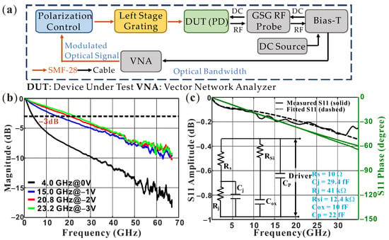
Figure 8.
(a) Experiment setup for the OE bandwidth measurement. (b) The frequency response of MM-PD. The 3 dB opto-electrical bandwidth reaches 23 GHz at −3 V bias. (c) Fitting of the real (black line) and imaginary (green line) of the measured PD S11 parameter at −3 V according to the equivalent small signal circuit model in the inset. In the model, is the junction resistance, is the junction capacitance, is the series resistance, is the parasitic capacitance between the electrodes, is the buried layer capacitance, and is the substrate contact resistance.
To analyze the reasons for the low photodetector bandwidth, the resistance and capacitance values of the V-NIP PD are extracted by fitting the real and imaginary parts of the small signal reflection (S11) parameter based on the equivalent circuit model [33] shown in the inset of Figure 8c. The fitting was performed using the genetic algorithm in Matlab. In the model, is the junction resistance, is the junction capacitance, is the series resistance, is the parasitic capacitance between the electrodes, is the buried layer capacitance, and is the substrate contact resistance. The difference between the reflected coefficients calculated based on the equivalent circuit and the measured one is used as the target optimization function, and the parameters to be extracted are used as optimization inputs. In addition, to reduce the influence of measurement noise at high frequencies, the weighting coefficient of low-frequency data is increased in the fitting process. The extracted values are displayed in the bottom right corner of Figure 8b. The RC limited 3 dB bandwidth can be evaluated up to 55.8 GHz according to these values, which is much higher than the measured one. This indicates that the limiting factor of the bandwidth is carrier transport.
3.4. Eye Diagram
On–off key data transmission experiments were carried out based on Figure 9a. A (2− 1) long electrical NRZ pseudo-random bit sequence data pattern, generated by an arbitrary waveform generator, was launched into a linear reference transmitter to generate a modulated optical signal. The modulated optical signal reached the photodetector through the grating coupler. A -3 V bias voltage was applied to the PD using a 50 GHz GSG RF probe connected to a 40 GHz bias tee. The photocurrent output was then measured with a Keysight N1000A oscilloscope with a 110 GHz remote sampling head plug-in. The 12.5 Gb/s, 25 Gb/s, and 50 Gb/s eye diagrams of the multi-mode waveguide input detector at −3 V bias are shown in Figure 9b. The clear eye diagrams indicate high-quality data reception of the MM-PD at 50 Gb/s in the O band. The data rate measurements are limited by the OE bandwidth of the V-NIP PD, which can be improved up to 100 Gb/s when using a high-bandwidth PD.
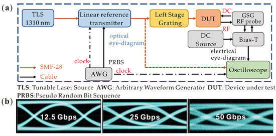
Figure 9.
(a) Experimental setup for the eye diagram measurement. (b) Measured 12.5 Gb/s, 25 Gb/s, and 50 Gb/s eye diagrams of the MM-PD.
4. Discussion
To scale up the capacity of optical communications and interconnects, there is a need for robust and low-cost silicon photonic WDM transmitters and receivers. However, the fabrication process can result in significant variation in the effective index of a silicon waveguide, leading to phase uncertainty when an optical signal propagates through the waveguide. This phase uncertainty makes it difficult to achieve accurate wavelength control in narrow-bandwidth components such as the AWG. The MM-WDM, which has a large passband, can effectively solve this problem and possesses the advantage of lower losses. In [34], a WDM receiver using a single-mode output AWG has a responsivity below 0.5 A/W, whereas a receiver using the MM-WDM achieved a responsivity greater than 0.7 A/W [28]. However, the coupling between MM-WDMs and detectors is only in sub-assembly, while a fully integrated WDM receiver has more potential to reduce cost and packaging complexity. As there is relatively little research on the on-chip implementation of MM-WDM and photodetector arrays, the multi-mode waveguide coupling method studied in this paper is meaningful.
In our experiment, a typical V-NIP PD configuration was directly used to confirm that the MM-PD had no significant performance degradation when compared with a T-PD. In V-NIP detectors, the doping of the Ge region leads to additional metal absorption, which reduces responsivity and increases dark current. These issues can be effectively addressed by using a lateral PD with Si contacts [35]. The electric field strength in the corner region of the 4 m wide and 500 nm high germanium waveguide is weak, resulting in limited bandwidth due to the long transit time of the photo-generated carriers in that region. Reducing the height of the germanium layer can effectively resolve this problem [36]. The use of a Si-Ge-Si heterojunction [32] can also enhance the confinement of the germanium waveguide, allowing the photo-generated carriers to be more concentrated in the center of the waveguide and alleviating this issue.
5. Conclusions
In this work, a multi-mode waveguide-integrated PD is demonstrated to show that the integration scheme can be effectively used as a component in the WDM receiver. It can be concluded that the MM-PD can effectively absorb different wavelength light, and it has no performance degradation in responsivity and OE bandwidth when compared with the reference single-mode input devices. The dark current of the PD in the experiment reaches below 50 nA at a bias of no more than −3 V. The OE bandwidth of the device for demonstration is 23 GHz at the bias of −3 V, and a clear NRZ 50 Gb/s eye diagram is observed, which indicates that 100 Gb/s at high-grade modulation is achievable. The flat transmission when connecting the MM-WDM and PD via a multi-mode waveguide is verified by sweeping the Y position of a single-mode input, which acts as an excitation source to simulate light coming from the MM-WDMs. As high-capacity co-packaged optics switch and intra-chip interconnection are about to enter the stage of volume applications, making full use of wavelength channels is an inevitable choice; thus, the results in this work provide very useful evidence for direct and effective on-chip coupling.
Author Contributions
Conceptualization, A.W. and L.W.; methodology, L.W. and D.L.; software, L.W. and R.W.; validation, L.W., D.L., N.Z., R.W., and A.W.; formal analysis, L.W.; writing—review and editing, L.W. and A.W. All authors have read and agreed to the published version of the manuscript.
Funding
This research was funded in part by the National Key Research and Development Program of China under Grant 2021YFB2206502, in part by the Program of Shanghai Academic Research Leader under Grant 22XD1404300, in part by the National Natural Science Foundation of China under Grant 62275259, and in part by the Youth Innovation Promotion Association CAS under Grant 2021232.
Institutional Review Board Statement
Not applicable.
Informed Consent Statement
Not applicable.
Data Availability Statement
The data supporting the reported results can be obtained from the authors.
Acknowledgments
The authors would like to thank the anonymous reviewers for their valuable comments and suggestions.
Conflicts of Interest
The authors declare no conflict of interest.
Abbreviations
The following abbreviations are used in this manuscript:
| Ge | Germanium |
| PD | Photodetector |
| OE | Opto-electronic |
| NRZ | Non-return-to-zero |
| WDM | Wavelength division multiplexing |
| SiPh | Silicon photonics |
| CMOS | Complementary Metal Oxide Semiconductor |
| L-PIN | Lateral P-I-N |
| AWG | Array waveguide grating |
| MM-WDM | WDM device with multi-mode waveguide output |
| T-PD | Typical Ge photodetector with single-mode input |
| MM-PD | Ge photodetector with multi-mode input |
| SOI | Silicon-on-insulator |
| V-NIP | Vertical N-I-P |
| CPO | Co-packaged optics |
References
- Biberman, A.; Bergman, K. Optical interconnection networks for high-performance computing systems. Rep. Prog. Phys. 2012, 75, 046402. [Google Scholar] [CrossRef] [PubMed]
- Chen, J.; Gong, Y.; Fiorani, M.; Aleksic, S. Optical interconnects at the top of the rack for energy-efficient data centers. IEEE Commun. Mag. 2015, 53, 140–148. [Google Scholar] [CrossRef]
- Wang, H.; Chai, H.; Lv, Z.; Zhang, Z.; Meng, L.; Yang, X.; Yang, T. Silicon photonic transceivers for application in data centers. J. Semicond. 2020, 41, 101301. [Google Scholar] [CrossRef]
- Won, R. Integrating silicon photonics. Nat. Photonics 2010, 4, 498–499. [Google Scholar] [CrossRef]
- Thomson, D.; Zilkie, A.; Bowers, J.E.; Komljenovic, T.; Reed, G.T.; Vivien, L.; Marris-Morini, D.; Cassan, E.; Virot, L.; Fédéli, J.M.; et al. Roadmap on silicon photonics. J. Opt. 2016, 18, 073003. [Google Scholar] [CrossRef]
- Wang, B.; Huang, Z.; Sorin, W.V.; Zeng, X.; Liang, D.; Fiorentino, M.; Beausoleil, R.G. A low-voltage Si-Ge avalanche photodiode for high-speed and energy efficient silicon photonic links. J. Light. Technol. 2019, 38, 3156–3163. [Google Scholar] [CrossRef]
- Michel, J.; Liu, J.; Kimerling, L.C. High-performance Ge-on-Si photodetectors. Nat. Photonics 2010, 4, 527–534. [Google Scholar] [CrossRef]
- Marris-Morini, D.; Vakarin, V.; Ramirez, J.M.; Liu, Q.; Ballabio, A.; Frigerio, J.; Montesinos, M.; Alonso-Ramos, C.; Le Roux, X.; Serna, S.; et al. Germanium-based integrated photonics from near-to mid-infrared applications. Nanophotonics 2018, 7, 1781–1793. [Google Scholar] [CrossRef]
- Hepgüler, G.R.; Madani, A.; Wagner, S.; Schall, D. Packaged Graphene Photodetectors with 50 GHz RF bandwidth operating at 1550 nm and 2 μm wavelength. In Proceedings of the Optical Fiber Communication Conference, San Diego, CA, USA, 8–12 March 2020; p. M3Z-8. [Google Scholar] [CrossRef]
- Huang, G.; Hao, Y.; Li, S.; Jia, Y.D.; Guo, J.; Zhang, H.; Wang, B. Recent progress in waveguide-integrated photodetectors based on 2D materials for infrared detection. J. Phys. D Appl. Phys. 2023. [Google Scholar] [CrossRef]
- DeRose, C.T.; Trotter, D.C.; Zortman, W.A.; Starbuck, A.L.; Fisher, M.; Watts, M.R.; Davids, P.S. Ultra compact 45 GHz CMOS compatible Germanium waveguide photodiode with low dark current. Opt. Express 2011, 19, 24897–24904. [Google Scholar] [CrossRef]
- Wang, J.; Loh, W.; Chua, K.; Zang, H.; Xiong, Y.; Tan, S.; Yu, M.; Lee, S.; Lo, G.; Kwong, D. Low-voltage high-speed (18 GHz/1 V) evanescent-coupled thin-film-Ge lateral PIN photodetectors integrated on Si waveguide. IEEE Photonics Technol. Lett. 2008, 20, 1485–1487. [Google Scholar] [CrossRef]
- Vivien, L.; Polzer, A.; Marris-Morini, D.; Osmond, J.; Hartmann, J.M.; Crozat, P.; Cassan, E.; Kopp, C.; Zimmermann, H.; Fédéli, J.M. Zero-bias 40Gbit/s germanium waveguide photodetector on silicon. Opt. Express 2012, 20, 1096–1101. [Google Scholar] [CrossRef] [PubMed]
- Byrd, M.J.; Timurdogan, E.; Su, Z.; Poulton, C.V.; Fahrenkopf, N.M.; Leake, G.; Coolbaugh, D.D.; Watts, M.R. Mode-evolution-based coupler for high saturation power Ge-on-Si photodetectors. Opt. Lett. 2017, 42, 851–854. [Google Scholar] [CrossRef]
- Chen, H.; Galili, M.; Verheyen, P.; De Heyn, P.; Lepage, G.; De Coster, J.; Balakrishnan, S.; Absil, P.; Oxenlowe, L.; Van Campenhout, J.; et al. 100-Gbps RZ data reception in 67-GHz Si-contacted germanium waveguide pin photodetectors. J. Light. Technol. 2016, 35, 722–726. [Google Scholar] [CrossRef]
- Zhou, D.; Yu, Y.; Yang, N.; Zhang, X. Germanium photodetector with alleviated space-charge effect. IEEE Photonics Technol. Lett. 2020, 32, 538–541. [Google Scholar] [CrossRef]
- Hu, X.; Wu, D.; Zhang, H.; Li, W.; Chen, D.; Wang, L.; Xiao, X.; Yu, S. High-speed and high-power germanium photodetector with a lateral silicon nitride waveguide. Photonics Res. 2021, 9, 749–756. [Google Scholar] [CrossRef]
- Novack, A.; Gould, M.; Yang, Y.; Xuan, Z.; Streshinsky, M.; Liu, Y.; Capellini, G.; Lim, A.E.J.; Lo, G.Q.; Baehr-Jones, T.; et al. Germanium photodetector with 60 GHz bandwidth using inductive gain peaking. Opt. Express 2013, 21, 28387–28393. [Google Scholar] [CrossRef]
- Lischke, S.; Peczek, A.; Morgan, J.; Sun, K.; Steckler, D.; Yamamoto, Y.; Korndörfer, F.; Mai, C.; Marschmeyer, S.; Fraschke, M.; et al. Ultra-fast germanium photodiode with 3-dB bandwidth of 265 GHz. Nat. Photonics 2021, 15, 925–931. [Google Scholar] [CrossRef]
- Brackett, C.A. Dense wavelength division multiplexing networks: Principles and applications. IEEE J. Sel. Areas Commun. 1990, 8, 948–964. [Google Scholar] [CrossRef]
- Dai, D.; Wang, Z.; Bauters, J.F.; Tien, M.C.; Heck, M.J.; Blumenthal, D.J.; Bowers, J.E. Low-loss Si 3 N 4 arrayed-waveguide grating (de) multiplexer using nano-core optical waveguides. Opt. Express 2011, 19, 14130–14136. [Google Scholar] [CrossRef]
- Pan, P.; An, J.; Wang, Y.; Zhang, J.; Wang, L.; Qi, Y.; Han, Q.; Hu, X. Compact 4-channel AWGs for CWDM and LAN WDM in data center monolithic applications. Opt. Laser Technol. 2015, 75, 177–181. [Google Scholar] [CrossRef]
- Pathak, S.; Dumon, P.; Van Thourhout, D.; Bogaerts, W. Comparison of AWGs and echelle gratings for wavelength division multiplexing on silicon-on-insulator. IEEE Photonics J. 2014, 6, 1–9. [Google Scholar] [CrossRef]
- Melati, D.; Verly, P.G.; Delâge, A.; Wang, S.; Lapointe, J.; Cheben, P.; Schmid, J.H.; Janz, S.; Xu, D.X. Compact and low crosstalk echelle grating demultiplexer on silicon-on-insulator technology. Electronics 2019, 8, 687. [Google Scholar] [CrossRef]
- Xu, H.; Liu, L.; Shi, Y. Polarization-insensitive four-channel coarse wavelength-division (de) multiplexer based on Mach–Zehnder interferometers with bent directional couplers and polarization rotators. Opt. Lett. 2018, 43, 1483–1486. [Google Scholar] [CrossRef] [PubMed]
- Xu, H.; Shi, Y. Flat-top CWDM (de) multiplexer based on MZI with bent directional couplers. IEEE Photonics Technol. Lett. 2017, 30, 169–172. [Google Scholar] [CrossRef]
- Doi, Y.; Ishii, M.; Kamei, S.; Ogawa, I.; Mino, S.; Shibata, T.; Hida, Y.; Kitagawa, T.; Kato, K. Flat and high responsivity CWDM photoreceiver using silica-based AWG with multimode output waveguides. Electron. Lett. 2003, 39, 1. [Google Scholar] [CrossRef]
- Madani, A.; Kleinert, M.; Stolarek, D.; Zimmermann, L.; Ma, L.; Schmidt, O.G. Vertical optical ring resonators fully integrated with nanophotonic waveguides on silicon-on-insulator substrates. Opt. Lett. 2015, 40, 3826–3829. [Google Scholar] [CrossRef]
- Doi, Y.; Oguma, M.; Yoshimatsu, T.; Ohno, T.; Ogawa, I.; Yoshida, E.; Hashimoto, T.; Sanjo, H. Compact high-responsivity receiver optical subassembly with a multimode-output-arrayed waveguide grating for 100-Gb/s Ethernet. J. Light. Technol. 2015, 33, 3286–3292. [Google Scholar] [CrossRef]
- Yoshimatsu, T.; Nakanishi, Y.; Tsunashima, S.; Nada, M.; Kamei, S.; Sano, K.; Ishii, Y. Receiver Integration with Arrayed Waveguide Gratings toward Multi-Wavelength Data-Centric Communications and Computing. Appl. Sci. 2020, 10, 8205. [Google Scholar] [CrossRef]
- Lumerical Is Now Part of the Ansys Family. Available online: https://www.lumerical.com/ (accessed on 9 March 2023).
- Virot, L.; Benedikovic, D.; Szelag, B.; Alonso-Ramos, C.; Karakus, B.; Hartmann, J.M.; Le Roux, X.; Crozat, P.; Cassan, E.; Marris-Morini, D.; et al. Integrated waveguide PIN photodiodes exploiting lateral Si/Ge/Si heterojunction. Opt. Express 2017, 25, 19487–19496. [Google Scholar] [CrossRef]
- Feng, D.; Qian, W.; Liang, H.; Kung, C.C.; Zhou, Z.; Li, Z.; Levy, J.S.; Shafiiha, R.; Fong, J.; Luff, B.J.; et al. High-speed GeSi electroabsorption modulator on the SOI waveguide platform. IEEE J. Sel. Top. Quantum Electron. 2013, 19, 64–73. [Google Scholar] [CrossRef]
- Zhao, Y.; Qiu, C.; Wu, A.; Huang, H.; Li, J.; Sheng, Z.; Li, W.; Wang, X.; Gan, F. Broadband polarization splitter-rotator and the application in WDM receiver. IEEE Photonics J. 2018, 11, 1–10. [Google Scholar] [CrossRef]
- Zhang, Y.; Yang, S.; Yang, Y.; Gould, M.; Ophir, N.; Lim, A.E.J.; Lo, G.Q.; Magill, P.; Bergman, K.; Baehr-Jones, T.; et al. A high-responsivity photodetector absent metal-germanium direct contact. Opt. Express 2014, 22, 11367–11375. [Google Scholar] [CrossRef] [PubMed]
- Chen, H.; Verheyen, P.; De Heyn, P.; Lepage, G.; De Coster, J.; Balakrishnan, S.; Absil, P.; Yao, W.; Shen, L.; Roelkens, G.; et al. -1 V bias 67 GHz bandwidth Si-contacted germanium waveguide pin photodetector for optical links at 56 Gbps and beyond. Opt. Express 2016, 24, 4622–4631. [Google Scholar] [CrossRef] [PubMed]
Disclaimer/Publisher’s Note: The statements, opinions and data contained in all publications are solely those of the individual author(s) and contributor(s) and not of MDPI and/or the editor(s). MDPI and/or the editor(s) disclaim responsibility for any injury to people or property resulting from any ideas, methods, instructions or products referred to in the content. |
© 2023 by the authors. Licensee MDPI, Basel, Switzerland. This article is an open access article distributed under the terms and conditions of the Creative Commons Attribution (CC BY) license (https://creativecommons.org/licenses/by/4.0/).