Abstract
Heating flame furnaces are the main type of furnaces used for heating and heat treatment of metal products in metallurgy and mechanical engineering. In the working chamber of a modern heating furnace, there should be neither high-temperature nor stagnation zones. One of the methods used to provide such combustion conditions is the application of distributed (volumetric) combustion. Owing to this method, heating quality is ensured by creating a uniform temperature field and equivalent heat exchange conditions, regardless of the placement of the charge in the working chamber of the furnace. In this work, we numerically study the volumetric combustion and influences of small- and large-scale recirculation ratios of furnace gases, the influence of temperature fluctuation on the regenerator nozzle, and the working parameters at the starting phase and reverse.
1. Introduction
Heating furnaces are commonly used to achieve the required product parameters, particularly in metallurgy. The main purpose of a metallurgical heating furnace is to provide the prescribed uniform temperature of ingots or other blanks before the next phase of processing.
To ensure the quality of the final product, a good knowledge of the thermal history of the workpiece is needed. The efficiency of the heating cycles can be evaluated by the following main parameters: the center of the ingot should reach a suitable temperature to avoid high gradients of temperature between the surface and the center during heating; the microstructure should be controlled and homogeneous; and the heating plan should ensure that the thermal stresses are sufficiently low [1]. Thus, the ideal heating conditions are achieved when the temperatures of each part of the ingot and its center are equal. The heat transfer from the furnace to the material, which depends essentially on the temperature distribution inside the furnace, significantly affects the quality of the final product [2].
In the working chamber of a modern heating furnace, there should be neither high-temperature nor stagnation zones. There are two main methods to achieve these uniform conditions:
- Increase the number of burners [3,4];
- Implement special conditions of combustion and circulation [5,6,7,8,9,10].
Reference [6] investigated the influence of heat recovery on the heating process. To unify the heating parameters, heat recovery equipment was installed. Nevertheless, it was concluded that most of the energy in the furnace is transferred by radiation, so the temperature fields of the furnace should be without stagnation zones to ensure the temperature uniformity of the heated material. Reference [7] investigated the optimum residence time with two slab requirements—temperature and uniformity. Results of the study show the influence of the uniformity of the temperature and heat flux on the uniformity of the slabs and on the length of the heating process. Reference [8] confirms results concerning the influence of the total heat flux fluctuation on the temperature uniformity of the slabs. The uniformity of the slab temperature in this case was achieved by moving the slabs to zones with different total heat flux to ensure equal heating conditions for each slab.
The proposed method of distributed (volumetric) combustion aims to unify the temperature and heat flux conditions in the heating furnace. Volumetric combustion means that heat is evenly distributed throughout the entire volume of the furnace. This is achieved by several means, such as the creation of special fuel combustion conditions; extended large-scale furnace gas recirculation; the attainment of highly dynamic flow characteristics of fuel and combustion products; the scientifically approved number of burners and flue gas exhausts and their location; other design parameters of the furnace and its elements; and the dynamic properties of furnace gases. With the elimination of combustion zones with temperature peaks, the rate of nitrogen oxide formation decreases, the probability of local overheating of the charge is eliminated, and the unevenness of the material structure and properties is reduced. The required heating quality is ensured by creating a uniform temperature field and equivalent heat exchange conditions, regardless of the placement of the charge in the working chamber of the furnace.
The design of the burner for the implementation of distributed volume-regenerative fuel combustion is associated with the following requirements:
- Ensuring the required heat output of the furnace.
- Selection of fuel and air flow areas that provide the combustion of fuel with specified mixing conditions.
- Performing the reverse flow and recirculation of the furnace gases.
- Heat transfer in the furnace working space according to the particular geometry.
2. Materials and Methods
2.1. The Principle of Implementing Volume Combustion
The principle of implementing distributed (volumetric) fuel combustion in the working space of a furnace with a regenerator as a result of the controlled mixing of fuel and air is described in detail in the patent [11]. The quantitative characteristics of the furnace atmosphere composition are illustrated in Figure 1.
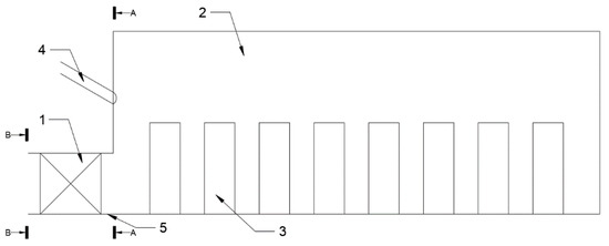
Figure 1.
Scheme of a reheating furnace with regenerators and with distributed volumetric combustion: 1—regenerator; 2—working chamber; 3—heated material; 4—gas nozzle; 5—flue gas ducts.
The fuel is fed to the heating furnace with a regenerator (1) via gas nozzles (4). After heating in the regenerator, the combustion air enters working chamber (2) with the heated material (3), through the flue gas ducts (5) which serve as air ducts or smoke windows, depending on the heating stage. The cross-sectional area of the gas nozzles and air ducts, and their number, geometrical shape, and relative positioning ensure such a degree of reagent mixing that the tolerable value of fuel non-combustion in the exhaust section is 0.1% to 5% and is completely absent at the exit B-B. In part A-A, where the fuel is discharged from the gas nozzles into the working space, the fuel is completely unburned. Gas fuel and air are mixed in the furnace working chamber (2).
When there is less than 0.1% of unburnt fuel at the exit of the furnace, it means that complete combustion occurs in the working chamber and the conditions for transition from volumetric combustion to flame combustion are created. If there is 0.1% to 5% unburned fuel at the exit of the chamber, there will also be oxygen that has not been used for combustion. Combustion continues even when the combustion products move from the chamber to the regenerator of the heating furnace. It is also possible to burn the fuel in the upper rows of regenerator nozzles. If the volume of unburnt fuel at the exit of the heating furnace chamber with the regenerator exceeds 5%, then the combustion process will also continue behind the regenerator, which will significantly reduce the fuel efficiency.
The organization of distributed volumetric combustion of fuel is possible by separating the fuel and air streams in the combustion facility and by providing such dynamic characteristics and suitable structural parameters of the furnace and its elements, where the specified mixing quality of the combustion reagents is ensured according to the patent [11]. By means of these characteristics, the trajectory of the necessary gases from the furnace, the maximum volume of the heat-release zone, and a uniform temperature field in the furnace working chamber are created.
The combustion rate of the fuel in the heating facility depends on the mixing speed of the flue gas. The chemical process of fuel combustion is incomparably faster than the physical process of mixing reagents.
2.2. Model
To study the character and efficiency of volumetric combustion, a mathematical model of the heating furnace was created. The burners are located on the shorter side of the furnace. The mathematical model was based on the solution of the heat balance equation taking into account the movement of furnace gases and their recirculation.
The boundary conditions of the furnace walls (except for the burner wall), the furnace bottom, and the ceiling are a 2nd-order quasi-adiabatic equation (defined as the heat flux across the boundaries):
The stream of gases with constant temperature enters through the burner wall in the first zone (3rd-order boundary conditions). Heat is transferred by convection and radiation. Convection was calculated as a part of the radiant energy. The wall in the last zone, where the exhaust gases leave the chamber, also has a 3rd-order boundary condition (defined as the environmental temperature and heat transfer coefficient):
where
- —environment temperature;
- time;
- coordinates;
- total heat transfer coefficient (convection and radiation).
The supplement to the 3rd-order boundary condition, radiant energy, is calculated as:
According to Equations (2)–(4), is calculated as
The calculation diagram, the dividing of the furnace into i elements, and the mass flow rates of the furnace gas circulation are shown in Figure 2. The working space of the heating furnace is divided into parts (zones) i = 2n, in each of which an ideal mixing is assumed. In each calculation zone i there is heated material [12]. The model works on the basis of fuel burn-out in the volume of the furnace chamber.

Figure 2.
Scheme of gas circulation inside the furnace. Red—2nd-order boundary conditions, blue—3rd-order boundary conditions.
The burner is installed in the first zone i = 1, and the flue gas window is located in the last zone i = 2n. The close, tight (on one wall) arrangement of the burner and the flue gas window contributes to the organization of extensive recirculation of the gases in the furnace, ensuring the appropriate kinetic energy of the stream from the furnace burners. This energy should ensure the movement of the furnace gases along the U-shaped trajectory in the furnace chamber, capturing and mixing the recirculation flow (shown in Figure 2 by an arrow connecting zones i = 2n and i = 1). The flue gas recirculation shown in Figure 2 is called large-scale recirculation.
In the centre of the furnace (Figure 3), at the boundary of the conditional separation of the gas flow from the furnace to the forward and return paths, there are local turbulent vortices that include layers of furnace gas moving forward and backward in the mass flow processes. Gas mixing in zones across the flow separation boundary is referred to as small-scale or local recirculation. Local recirculation, together with large-scale internal recirculation of the furnace gases, also affects the temperature field in the furnace. The presence and degree of development of local furnace gas circulation zones can change the regime of smoke movement in the furnace over a wide range: from the “short circuit” mode to the development of decompensated mixing, with the return flow of part of the furnace gas mass flow to the initial part of their path (recirculation regime). The intermediate state with small-scale compensated mixing [5] is called displacement with a compensated mixing regime. The occurrence of both regimes of movement in real conditions depends on the energy of the gas flows from the furnace.

Figure 3.
Calculation scheme of the furnace and the scheme of movement of furnace gases.
The heat balance of the heating furnace with a U-loop gas path in the furnace chamber is represented as
2.2.1. Heat Gains
The input parts of the heat balance for the i-th zone are calculated according to Equations (7)–(16). Air, fuel, and exhaust gas heat in zone i = 1 are given by the following relationship:
This equation was derived in article [13] from the Heiligenstedt equation.
The mean temperature along the entire flame length is given by the following relationship:
where the flame residence time in the furnace is calculated from the geometric volume of the combustion chamber and the furnace gas consumption per second , given by the equation
and the heat transfer rate along the flame length m depends on the initial gas velocity
where
- —heat capacity, (J/(kg K));
- consumption, (kg/s);
- actual combustion air consumption, (m3 air/m3 fuel);
- temperature of heated air, (°C);
- air heat capacity, (J/(m3 K));
- heat (thermal power), (W);
- k—coefficient of the heat-release process, depending on the burner design, tubular k = 4 … 6, pre-mix k = 8 … 10, martin head = 1.5 … 2 [14];
- initial amount of heat of combustion products, (J/m3);
- actual amount of heat in time τ, (J);
- —material surface temperature, (°C).
In areas I = 2 … 2n, the air, fuel, and exhaust gas heat is as follows:
where
- j = 2n − k + 1.
- vexg—specific exhaust gases output during combustion, (m3/m3).
- tmix−1—temperature of the mixture of fuel, air, and exhaust gases in the (i − 1)-th zone of the furnace, °C. In the sense that we have applied a law of fuel combustion (exponential), the next zone receives unburned fuel, unused air, and exhaust gases from the previous zone.
- —fraction of fuel burned in the k-th zone;
- — heat capacity of the exhaust gases, (J/(m3 K));
- —density of the exhaust gases, (kg/m3).
Heat of combustion products passing through the furnace gas flow interface on the straight and reverse path is as follows:
The value of is determined by the law of the distribution of mass flow density of combustion products through the interface between the forward and reverse trajectories of their movement. For this purpose, the following formula can be used:
where
G—mass flow.
In Equation (13), relative length of small-scale recirculation; coordinate of zone i centre; zone lengths i; b—distribution function exponent; exhaust gas recirculation coefficient, ; i and j—the numbers of the zones of the outlet and inlet of the recycle gas flow, related by the ratio j = 2n − i + 1.
The coefficient of recirculation is found from the energy balance equation that includes pressure losses in all parts of the furnace gas path from the burner to flue gas windows and is related to the specific circulation energy, based on 1 m3 of furnace gas, as follows:
where
Nspec—specific energy of circulation. The circulation rate and flow path length depend on the amount of kinetic energy in 1 m3 of furnace gases that may be spent to overcome the movement resistance in (Pa) in the furnace and to include recirculation gases in the satellite motion [15], given by the following relationship:
where
- density under operating conditions of fuel, air, and exhaust gases, (kg/m3);
- average speed under operating conditions of fuel, air, and exhaust gases, (m/s)
- volumetric consumption of fuel, air, and exhaust gases under operating conditions, (m3/s);
- temperature of fuel, air, and exhaust gases, (°C);
- equivalent coefficient of resistance to friction of a moving gas in the furnace = 0.3;
- average length of the trajectory of the exhaust gases, (m);
- equivalent diameter of a stream of exhaust gases, (m).
The distribution function in Equation (13) is selected in a such way that the change in exponent b results in the change of mass flow through the zones from the one equally spaced along a half-path to the concentrated one in the radical flame zone.
Heat released by the fuel combustion is given by the following equation:
where
- —fraction of fuel burned in the i-th zone;
- net calorific value, (J/m3);
Change in the relative fuel concentration over the entire flame length is considered an exponential dependence.
2.2.2. Heat Losses
Output parts of the heat balance of the i-th zone are calculated according to Equations (17)–(19). Heat consumed to heat up the material in the zone is given by the following relationship:
where
- metal surface area in the i-th zone, (m2);
- temperatures of the mixture of fuel, air, and exhaust gases, and the surface of the material in the i-th zone of the furnace, (°C);
- equivalent coefficient of radiation in the zone with respect to the conduction, as a fraction of radiation (5%–10%), (W/(m2 K4)).
Heat loss through furnace walls in the calculation zone is given by the following equation:
where
- gradation of furnace laying;
- coefficient of heat transfer to the environment, (W/(m2·K));
Heat loss of furnace gases leaving the i-th zone is given by the following relationship:
The heat balance for each calculation zone is solved sequentially from i = 1 to i = 2n. The temperature of the furnace gases (a mixture of fuel, air, and exhaust gases in proportion to the selected fuel combustion law) is determined in each of the calculation zones.
Based on the described mass flow calculation, the model introduces the concept of local small volume recirculation—turbulent vortices—which include furnace gas layers moving forward (zones i = 1 … n) and backward (zones i = (2 + 1) … 2n) across the flow zone boundaries (Figure 3).
The mathematical model is based on a heat balance calculation. According to the assumed methodology, heat balances of the whole furnace and every calculation zone were derived separately. The heat balance of the furnace was calculated to control the total amount of input and output heat, while the heat balances of the zones were calculated to understand the large- and small-scale recirculation and its influence, as well as the heat parameters.
2.3. Model Validation
To study the character, efficiency, and dynamic parameters of volumetric combustion, mathematical model calculations of a heating furnace with a U-loop trajectory of gases were performed. The mathematical model was solved on the basis of a previous study, the patent, and a physical model, and was compared with real measurements. The furnace has a quadratic shape, so the numerical grid was also chosen on a quadratic basis. The quadratic shape chamber was divided by 16 equal calculation zones (n = 8), as shown in Figure 3. Such a calculation grid was assumed to unify, where possible, the furnace conditions in each calculation zone. The calculation grid was chosen in such a way that each zone has the heated material at its middle. According to this, the numerical grid is in high conformity with the real model shape. Nevertheless, the model has some simplifications connected to the exhaust gas fluid dynamic processes, which are insignificant, according to the Reynolds and Kolmogorov theories, with respect to the thermal balance calculation. The article does not study the influence of the turbulence energy around the exhaust gas channels and burners, or the turbulence caused by the shape of the heated material. According to the Reynolds and Kolmogorov theories, the vortex turbulent energy is irrelevant to the total circulation energy.
Every calculation zone has six calculation surfaces. Thus, every calculation zone has a minimum of three (zones 1, 8, 9, and 16 have four) of the six calculation surfaces defined as boundary surfaces. Such boundary surfaces have 2nd-- or 3rd order boundary conditions according to Equations (1)–(5). The other surfaces of the calculation zones are interfaces and are calculated according to Equations (6)–(19).
The first flue gas recirculation studies were performed in hydraulic transparent chamber models with ingots in a linear ratio of 1:10. Experiments were performed to determine the ratio of large-scale recirculation using the radioactive isotope of cobalt-60. The recirculation ratio determined by the radioactive method was approximately 1.92 [16].
The measurements on the real device were performed in the heating furnace (Figure 4). Dimensions of the working chamber of the furnace were 10 × 4 × 3 (m). Dimensions of ingots were 2.35 × 0.8 × 0.9 m. The length of zone i was 1 m. The number of zones was 16. Two thermocouples were installed in each zone (one on the ceiling and the other on the wall), except for zones 8 and 9, where there were three thermocouples in each (one more on the wall against the burner).

Figure 4.
Reheating furnace and locations of installed thermocouples. 1—burners, 2—regenerators, 3—working chamber, 4—calculation zones.
The following measuring devices were used:
- Thermocouple K type, diameter 6.5 mm, max. temperature 1370 °C;
- AC/DC converter;
- Data logger.
The metal heating process consists of two stages: stage 1—heating to maximum constant heat output (maximum constant fuel consumption); stage 2—keeping the furnace temperature constant. As a fuel, a typical metallurgical mixture of coke and blast furnace gases was used. The fuel composition is shown in Table 1.

Table 1.
Composition of the fuel.
The calorific value of the fuel was = 6.7 (MJ/m3). Fuel consumption in the 2nd stage exponentially decreased from the maximum to the minimum value. Maximum fuel consumption in the first stage was = 5700 (m3/h) = 1.8 (kg/s); heated fuel temperature = 300 (°C); heated air temperature = 800 (°C); heated metal surface area = 7.62 (m2); actual combustion air flow = 1.61 (m3/m3) = 1.83 (kg/kg).
It was assumed that non-combustion of chemical fuel in the furnace equals 1%. The whole combustion process in the calculations was represented as a stoichiometry combustion calculation according to the work parameters of the measured furnace. The simulation and measurement results are shown in Figure 5.
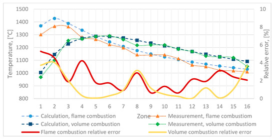
Figure 5.
Results of the simulation and measurements.
Figure 5 shows the average furnace wall temperatures in each zone of the furnace; these temperatures are compared to calculated values. The lines of the measured values represent average temperatures from the five replicated measurements. The accuracy of the model calculated from measured and calculated results of the furnace wall temperature was approximately 1.4%–2.45%. All input parameters, such as volume of the fuel and oxidizer, their temperatures, and composition, were controlled by the measurement and combustion equipment. The simulation was performed under the same experimental conditions to verify the reliability of this document due to a lack of volumetric combustion data.
3. Results
3.1. Calculation of Flame and Volume Combustion
Based on the physical model and input parameters, a series of calculations of flame (dimensionless heat-release zone of 0.19) and volume combustion (dimensionless heat-release zone above 0.31) were performed. The results of the calculations are shown in Figure 6.

Figure 6.
The change of the temperature of the flue gases during their movement in the heating furnace at various values of the dimensionless length of the heat-release volume zone.
Calculations showed that an increase in the dimensionless heat-releasing volume zone from 0.19 to 0.94 resulted in a nearly 10% reduction in the maximum temperature in the furnace zones.
The temperature variation in the furnace zones, expressed as a standard deviation, was reduced by almost 40% (Table 2). However, the average temperature in the furnace practically did not change. Thus, the volume of the heat-release zone significantly affected the fuel combustion zone, so the temperature field uniformity in the heating furnace is of great importance.
Table 2.
Results of the calculation of flame and volume combustion.
3.2. Volume Combustion Behaviour with Different Recirculation Ratios
The modelling results of temperature distribution in the heating furnace at different internal parameters of furnace gas recirculation are shown in Figure 7, Figure 8 and Figure 9. The temperature distribution in the furnace zones is shown at maximum heat output with maximum and minimum resulting heat flow per charge (Figure 7 and Figure 8) and at minimum heat output in the furnace (Figure 9).

Figure 7.
Temperature distribution over the zones of the furnace with variable rate of recirculation of furnace gases with minimum thermal power.

Figure 8.
Temperature distribution over the zones of the furnace with variable rate of recirculation of furnace gases with maximum heat output and minimum resulting heat flux to metal.

Figure 9.
Temperature distribution over the zones of the furnace with variable rate of recirculation of furnace gases with minimum thermal power.
The maximum dimensionless temperature unevenness in the furnace zones, expressed as the ratio of the furnace temperature difference to its average temperature, decreased from 34% to 14%–16% (from 438 °C to 175–206 °C; Table 3) with an increase in the recirculation rate from = 1 to = 4–5; increasing recirculation to = 7 reduced the dimensionless temperature unevenness by another 2%. A further increase in recirculation was ineffective: with = 10, the temperature field inconsistency remained almost unchanged [15].
Table 3.
Results of the calculation of volume combustion with different recirculation rates.
Based on the movement of furnace gases along a U-loop path, it can be said that large-area internal recirculation had a significant effect in creating a homogeneous temperature field in the furnace working space.
The maximum temperature field unevenness in the heating furnace (Figure 7, Figure 8 and Figure 9) for any value of the internal furnace gas recirculation ratio occurred when the charge was heated with the maximum heat output at the minimum resulting heat flow per charge under the heat transfer conditions. Intensification of the furnace gas recirculation can reduce the temperature field unevenness in the furnace to an acceptable value. From the diagrams and the obtained approximation functions, it is possible to determine the desired value of the large-scale internal flue gas recirculation ratio in the furnace, which ensures uniform technologically acceptable temperature.
3.3. Influence of Local Recirculation
A series of simulations was performed to determine the effect of the local small-scale furnace gas recirculation ratio on the temperature field in the working chamber and the temperature distribution in the furnace zones with varying degrees of small-scale recirculation distribution.
The value of the b coefficient, which describes the uniform distribution of local recirculation in the furnace, varied from 0.1 to 100. This interval reflects cases of uniformly distributed local recirculation along the entire length of the furnace (within the limit b → 0) across all adjacent furnace gas path zones, and cases with total elimination of local recirculation (b → ∞) when gases move along the U-loop trajectory without displacement through the central axis of the furnace, similar to the “ideal displacement” mode.
The distribution of the mass flow of furnace gas recirculation flow in pairs of zones 1–16 … 8–9 (Figure 3) is shown in Table 4. The value of b = 0.5–1.5 corresponds to the natural degree of development of local vortex zones at velocity and viscosity values corresponding to the actual conditions. As the mass flow distribution exponent increases, b ≥ 10.0, radical furnace gas recirculation is observed, with the main flow of the medium passing through zones 1–16 and 8–9 adjacent to the short burner and exhaust window walls.
Table 4.
Distribution of the mass flow rate of furnace gas streams in pairs of furnace zones depending on the small-scale circulation exponent b.
The temperature distribution in the furnace working space was compared when the batch was heated with the minimum resulting heat flow at the maximum heat output with varying degrees of local recirculation development. In all calculation options, the furnace gas recirculation was assumed to be constant, = 2. The calculation results are shown in Table 5.
Table 5.
Distribution of the mass flow rate of furnace gas streams in pairs of furnace zones depending on the small-scale circulation exponent b.
The results of the calculations show that the local recirculation of the furnace gases also affects the formation of the temperature field in the furnace with the U-loop trajectory. When the local recirculation value changes from zero (at b = 10) to its maximum value, = 2 (at b = 0–0.1), the temperature difference between the warmest i = 5 and the coldest i = 1 furnace zones is increased by more than 15% (from 282 to 334 °C) [15]. The decrease of the heating uniformity is associated with the decrease of the temperature gradient of the mixing gases and the decrease of the heat transfer intensity.
The smallest value of the standard deviation of the temperature in the furnace zones corresponds to the case when there is a significant large-scale recirculation of the furnace gases (b = 100). In this case, the temperature difference between the zones of the heating furnace with the U-loop trajectory of the furnace gases is minimal.
Local recirculation of furnace gases can be reduced by eliminating the causes of local vortexes during gas movement, such as obstacles in the path of furnace gas movement (batch, furnace masonry, mechanisms, etc.), sudden changes in the direction of their movement, and other local resistances. Such barriers reduce the kinetic energy, thereby reducing the value of the large-scale recirculation of the moving furnace gases, resulting in a reduction in the heating standard of the batch.
The results of studies of the influence of gas-dynamic characteristics of furnace gases on the uniformity of the temperature field in the heating furnace were also confirmed by the operation of a regenerative heating furnace (well-type) with a central position of the burner [15].
3.4. Influence of Temperature Fluctuation on the Regenerator Nozzle
A characteristic property of the regenerators is an unsteady temperature field in the regenerator air nozzle and a periodic change of the heating air and exhaust gas temperatures. The heating time of the metal in the furnace is much longer than the time between the reversals of the furnace gases, so the process of air heating in the regenerators, which is repeated cyclically in different cycles, can be considered quasi-stationary.
It is known that the performance of regenerative heat exchangers is influenced by the design parameters of the heat exchangers and the operational characteristics of their work.
Table 6 shows the results of the calculations of the ratio change of the fuel amount movement to the total momentum of reactants ΔI when the heating air temperature changes from 100 to 400 °C in one cycle.
Table 6.
Change of the ratio of the fuel amount movement to the total momentum of the reactants at various actual air flow rates.
Volumetric combustion of fuel with such a change of the heating air temperature did not change to flame burning. When heating the furnace with a lower calorific value fuel (Table 6), the effect of the air heating temperature variation on the pulse ratio was less significant.
3.5. Working Parameters of the Furnace and Regenerators at the Starting Phase
By heating the furnace from a cold state (which is typical of most heat furnaces), the heating temperature of the air in regenerators increases proportionally to the temperature in the furnace working space and the flue gas temperature. At the same time, there is a certain operating temperature in the furnace for which the burner outputs, piping, dimensions, etc., are designed. For this nominal power, design parameters and dynamic characteristics of the furnace gases are determined to ensure distributed volumetric combustion of the fuel.
The results of calculating the change in the ratio of the fuel pulse to the total pulse of the combustion agents with the increasing heating temperature of the generator nozzle air from 0 °C to 1200 °C are shown in Table 7.
Table 7.
Influence of the amount of air heating in regenerators on the organization of volume fuel combustion; F—flame, V—volume.
With the reduction of the total heat output (fuel consumption) from the nominal value to zero, the ratio of the amount of fuel movement to the total momentum of combustion agents does not change at any air temperature, explained by linear airflow dependence and momentum on fuel consumption (and impulse).
It is impossible to provide volume-regenerative combustion of the fuel over a wide range of air temperatures without changing the gas-dynamic characteristics of the combustion agents (mainly due to the surface area of the outlets). Such dependence of the controlled mixing conditions of the reagents and the distributed fuel on the combustion air temperature causes difficulties in generating volumetric regenerative combustion in the heat furnaces. The temperature decrease of the heated air in the regenerators or in heating their nozzles leads to an increase of flame burning possibility. In addition, lowering the air heating temperature below 700 °C not only converts the combustion to flame burning (Table 6), but also does not allow volumetric combustion due to the temperature drop of the fuel–air mixture below the ignition temperature, which is contrary to the principle of such combustion.
3.6. Reverse of Furnace Gases during Volumetric Fuel Combustion in Furnaces with Regenerators
In studies dealing with the reverse flow of furnace gases and their effect on the uniform heating of the furnace charge, the natural degree of development of local furnace gas recirculation at b = 1 was accepted.
Figure 10, Figure 11 and Figure 12 and Table 8 show the results of calculating the temperature field in the furnace at various furnace gas recirculation ratios. Data on the maximum, average, and minimum temperatures in the furnace zones, on the temperature field unevenness, and on the degree of unevenness expressed by the estimate of the mean square deviation of the temperature were obtained at the minimum and maximum heat output and the different resulting heat flows per batch.

Figure 10.
The temperature distribution in the zones of the furnace at MTotal = max (qtotal = max) with a variable rate of recirculation of furnace gases with minimum thermal power.

Figure 11.
The temperature distribution in the zones of the furnace at MTotal = max (qtotal = min) with a variable rate of recirculation of furnace gases with minimum thermal power.

Figure 12.
The temperature distribution in the zones of the furnace at MTotal = min with a variable rate of recirculation of furnace gases with minimum thermal power.
Table 8.
The results of calculating the uniformity of the temperature field during reverse movement of furnace gases for different rates of their recirculation.
Unevenness of the temperature field over the entire length of the furnace increased at = max and reached its maximum value at = max, and the resulting flow per charge decreased. Further, as the thermal energy decreased, the temperature field unevenness decreased significantly and reached the minimum value at = min. Figure 13 shows the temperature drop dynamics over the entire length of the furnace during metal heating when = 2. Furthermore, a lower recirculation rate of the gas furnace led to greater unevenness in the temperature field in the furnace.

Figure 13.
Change in the temperature differential across the zones of the furnace with a change in thermal power (for the case with Krec = 2). The time of changing the heating parameters from the red to the yellow line is the first heating period; from yellow to green is the second.
The results of the comparison of the calculation of the temperature field during the return movement of the furnace gases with the calculated data given in Section 2.3 are given in Table 8. Based on the temperature distribution in the furnace regardless of the flame reversal, it can be stated that the degree of temperature compensation due to reversal in the regenerative combustion system reaches 30%–40%. Thus, for one calculation option, after reversing the direction of furnace gas flow at = max ( = min), the temperature field unevenness (temperature difference over the entire length of the furnace) decreased from 438 to 268 °C at ideal furnace gas displacement = 1, from 175 to 119 °C at = 5, and from 100 to 68 °C at = 10. As the furnace gas recirculation rate increased, the effect of the reverse reaction on the degree of temperature equalization over the entire length of the furnace was slightly reduced.
Reversing the movement direction of the furnace gases in the heating furnaces thus leads to a significant increase of the temperature field uniformity in the furnace and to an improvement in the metal heating standard.
4. Discussion
One of the most important factors in the steel heating process is the uniformity of the temperature field inside the furnace. References [17,18] report on ways to increase the energy efficiency of billet heating by reducing the heat loss of related operations. Alex M. García et al. [4] reported that the position and type of burners have a great effect on the performance of a walking-beam type reheating furnace, in terms of efficiency and product quality. When the burners were located in the rear wall of the furnace, a greater radiation heat flux was obtained. The higher wall and gas temperatures at the furnace inlet (wall opposite the burners) explain the larger fluxes. The configuration with burners located in parallel on the sidewall promoted an increase in the heat transfer rate by convection compared to radiation. Nevertheless, the temperature difference across the furnace zones was approximately 250 °C.
The results published in this article are comparable with the results described in these publications. In this study, a volumetric combustion method was used to heat the metal blanks in the heating furnace. Such a combustion method, in combination with heat regenerators, can provide better uniformity of temperature fields in the furnace working chamber. The temperature difference in the furnace zones at the maximum dimensionless heat-release length (0.94) was 79 °C, expressed as a standard deviation of the temperature. Thus, the calculations confirm the conclusion that the combustion of fuel distributed over the entire length of the trajectory contributes to the creation of standard conditions for the heating of the batch in heating furnaces with high-temperature heating by regenerators.
Yukun Hu et al. [19] developed a first-principles hybrid model for large-scale reheating furnaces. This combination of the classical zone method of radiation analysis and computational fluid dynamics (CFD) functions more quickly than real-time monitoring (elapsed time of the process was 16 min at dt = 5 s). The C+ program was used to calculate the volume combustion of fuel. The use of a mathematical model allows a rapid prediction of the process of heating the material and thus also the reaction of the staff to the ongoing processes. The calculation time of the whole heating process (heating time 2 h) with dt = 10 s was approximately 2 min.
5. Conclusions
Ensuring the presumed mixing of the components of combustion and volumetric combustion in high-temperature heating furnaces with modern regenerators is possible thanks to the design parameters of the furnaces and their elements and the gas-dynamic properties of the furnace gases, where
- In the volumetric combustion zone, the temperature of the fuel–air mixture is equal to or higher than the ignition temperature of the fuel due to the heating of the air in the regenerators at a high temperature. By the means of controlled mixing of the combustion components, it is possible to ignite the fuel with any amount of oxidizing agent and to ensure the distribution of combustion along the entire trajectory of the furnace gases;
- The combustion agents are separated in the fuel combustion plant, have no more than 10% difference in the flow momentum of the fuel and the high-temperature air, and the length of the volumetric heat release zone is equal to the length of the gas path in the furnace;
- The specific furnace gas energy provides global internal furnace gas recirculation in the range Krec = 1.8–5;
- There are no stagnant zones, or there is no steel (batch) in these zones, and local gas recirculation in the furnace is minimized;
- Periodic reversal of the flow direction of the gases from the furnace is performed;
- The allowable amount of unburnt fuel at the furnace exhaust is 0.1%–5%, provided that the fuel is completely burnt in the regenerator gas pipeline or in the upper rows of the regenerator exchanger.
The influence of the dynamic characteristics of the furnace gases was investigated: the volumetric heat release zone, the global and local furnace gas recirculation, their feedback on the temperature field uniformity, and the furnace heating quality. The decisive influence of these characteristics on the conditions of the volumetric combustion of fuel in heating furnaces with high-temperature air heating was shown.
Increasing the dimensionless length of the heat-generating volumetric zone from 0.19 to 0.94 leads to a 10% reduction of the maximum temperature in the furnace zones, and the temperature unevenness in the furnace zones (as an estimate of the mean square deviation) decreases by almost 40%.
The maximum dimensionless temperature unevenness in the furnace zones, which can be expressed as the ratio of the temperature difference in the furnace to the average temperature, decreases from 34% to 14%–16% with an increase of the recirculation rate from Krec = 1 to Krec = 4–5. Increasing recirculation to Krec = 7 reduces the dimensionless unevenness of the temperature field by another 2%. Further increase of recirculation is ineffective: the dimensionless temperature unevenness of the field remains almost unchanged as the recirculation increases to Krec = 10.
Dependence diagrams of the maximum temperature difference over the entire length of the furnace on the multiplicity of furnace gas recirculation for the furnace with the furnace gas U-loop movement were plotted. The use of these dependencies and approximation functions allows us to determine the desired values of the recirculation rates that correspond to the technologically permissible temperature unevenness in the furnace.
With the increase of the small-scale local recirculation rate, the temperature field unevenness in the furnace may increase by 15%. The reduction of local small-scale recirculation is associated with the removal of obstructions and local resistances along the furnace gas path, or with a rapid change of the gas movement direction.
The maximum temperature difference over the entire length of the furnace decreases more than 1.5 times due to the return flow of the furnace gases. In the calculation for the furnace with a loop furnace gas path, the temperature difference in the furnace decreased from 438 to 268 °C at Krec = 1; from 175 to 119 °C at Krec = 5; and from 100 to 68 °C at Krec = 10.
The maximum change in the air heating temperature to 400 °C during the regenerator operation cycle does not significantly affect the amount of movement of the reagents and cannot be a limiting factor in the design of the heating furnaces with distributed fuel combustion. If the regenerator exchanger is heated from a cold state, when air heating level is less than 60% of the calculated temperature, combustion is in flame mode.
Fluctuations in the air heating temperature and the associated periodic changes in the heat flow do not affect the steel heating quality and the performance of the high-temperature air heating furnace with regenerators. The quality of heating of heat-massive metal in furnaces equipped with regenerative burners is no worse than similar recuperative heating (in terms of air heating). The heating time and the capacity of the recuperative furnace differ from those for the recuperative furnace by a maximum of 0.5%. At the same time, unlike in regenerators, it is difficult to achieve a deep utilization of flue gas heat in recuperative heat exchangers.
6. Patents
Ukraine Patent 26272, MPK F23N 5/26.
Author Contributions
Conceptualization, M.R. and M.F.; methodology, O.Y.; software, A.K.; validation, K.S., O.G. and E.B.; formal analysis, R.B.; data curation, M.R.R.; writing—original draft preparation, A.K.; writing—review and editing, M.R. and O.Y.; visualization, M.S. All authors have read and agreed to the published version of the manuscript.
Funding
This work was supported by the Slovak Research and Development Agency under the contract No. APVV-16-0192.
Conflicts of Interest
The authors declare no conflict of interest.
References
- Romano-Acosta, L.F. Optimization of Heating Cycles Prior Forging for Large Steel Ingots Based on a Simulation Model. Mater. Perform. Charact. 2018, 7, 33–48. [Google Scholar] [CrossRef]
- Nima, B.A.; Yassine, B.; Farzad, B.T.; Mohammad, J.; Morin, J.B.; Jahazi, M. Experimental and unsteady CFD analyses of the heating process of large size forgings in a gas-fired furnace. Case Stud. Therm. Eng. 2019, 14, 100428. [Google Scholar] [CrossRef]
- Kesavan, V.; Srinivasan, M.; Ramasamy, P. The Influence of Multiple-Heaters on the Reduction of Impurities in mc-Si for Directional Solidification. Silicon 2019, 11, 1335–1344. [Google Scholar] [CrossRef]
- Alex, M.G.; Andres, F.C.; Julian, E.O.; Carlos, E.A.; Andres, A.A. Effect of the burner position on an austenitizing process in a walking-beamtype reheating furnace. Appl. Therm. Eng. 2019, 153, 633–645. [Google Scholar] [CrossRef]
- Wang, C.; Zhou, Y.; Liang, Z.; Yang, F. Heat transfer simulation and thermal efficiency analysis of new vertical heating furnace. Case Stud. Therm. Eng. 2019, 13, 100414. [Google Scholar] [CrossRef]
- Alex, M.G.; Andrés, A.A. A numerical analysis of the effect of heat recovery burners on the heat transfer and billet heating characteristics in a walking-beam type reheating furnace. Int. J. Heat Mass Transf. 2018, 127, 1208–1222. [Google Scholar] [CrossRef]
- Sang, H.H.; Daejun, C. Optimum residence time analysis for a walking beam type reheating furnace. Int. J. Heat Mass Transf. 2012, 55, 4079–4087. [Google Scholar] [CrossRef]
- Gu, M.Y.; Chen, G.; Liu, X.; Wu, C.; Chu, H. Numerical simulation of slab heating process in a regenerative walking beam reheating furnace. Int. J. Heat Mass Transf. 2014, 76, 405–410. [Google Scholar] [CrossRef]
- Dzurnak, R.; Varga, A.; Kizek, J.; Jablonsky, G. Influence of Burner Nozzle Parameters Analysis on the Aluminium Melting Process. Appl. Sci. 2019, 9, 1614. [Google Scholar] [CrossRef]
- Eun, C.L.; Seung-Won, C. A Numerical Study on the Characteristics of Air–Fuel Mixing Using a Fluidic Oscillator in Supersonic Flow Fields. Energies 2019, 12, 4758. [Google Scholar]
- Yeromin, O.O.; Oleksandr, Y.; Volodymyr, H.; Artem, S. Volume-Regeneration Method for Fuel Burning at Metal Heating. Ukraine Patent 26272, 10 September 2007. [Google Scholar]
- Yeromin, O.O. Organization of regulated combustion of fuel in heating furnaces with the aim of creating a uniform temperature field. Metall. Heat Eng. Collect. Artic. Sci. 2012, 4, 78–83. [Google Scholar]
- Norkin, N.N. Studies of Convective-Turbulent Combustion. Bulletin of the Tomsk Order of the Red Banner of Labor of the S. Kirov Polytechnic Institute. 1952, Volume 69, pp. 120–147. Available online: https://cyberleninka.ru/article/n/issledovanie-fakelnogo-konvektivno-turbulentnogo-goreniya/viewer (accessed on 27 February 2020).
- Norkin, N.N. Convective-turbulent combustion flare studies, Bulletin of the Tomsk Order of the Red Banner of Labor named after S.M. Kirov Polytech. Inst. 1952, 69, 120–147. [Google Scholar]
- Yeromin, O.O. Influence of the dynamic characteristics of fuel and air jets on the circulation and temperature field of gases in a chamber furnace with one burner. Technol. Therm. Phys. Ind. Therm. Energy Zb. Sci. Pr. 2011, 3, 102–116. [Google Scholar]
- Gubinsky, V.I.; Zhung, U.L. Flame Furnaces Theory; Mashinostroenie Publishers: Moscow, Russia, 1995; pp. 101–111. [Google Scholar]
- Chen, D.; Lu, B.; Dai, F.; Chen, G.; Yu, W. Variations on billet gas consumption intensity of reheating furnace in different production states. Appl. Therm. Eng. 2018, 129, 1058–1067. [Google Scholar] [CrossRef]
- Chen, D.; Lu, B.; Zhang, X.; Dai, F.; Chen, G.; Liu, Y. Fluctuation characteristic of billet region gas consumption in reheating furnace based on energy apportionment model. Appl. Therm. Eng. 2018, 136, 152–160. [Google Scholar] [CrossRef]
- Yukun, H.; Tan, C.K.; Broughton, J.; Roach, P.A. Development of a first-principles hybrid model for large-scale reheating furnaces. Appl. Energy 2016, 173, 555–566. [Google Scholar] [CrossRef]
© 2020 by the authors. Licensee MDPI, Basel, Switzerland. This article is an open access article distributed under the terms and conditions of the Creative Commons Attribution (CC BY) license (http://creativecommons.org/licenses/by/4.0/).