Abstract
Landfill is still the most important process to dispose of municipal solid waste in China, while landfill closure aims for pollution control, security control, and better land reuse. However, uneven settlement of landfill cover system is very likely to cause deformation and cracking. The objective of this paper is to examine the effects of geogrid reinforcement on the deformation behaviour and hydraulic conductivity of the bentonite-sand mixtures that are subjected to differential settlement. The laboratory model tests were performed on bentonite-sand mixtures with and without the inclusion of geogrid reinforcement. By maintaining the type and location of the geogrid within the liner systems as constant, the thickness of the bentonite-sand mixtures is varied. The performation of the liner systems with and without the inclusion of geogrid reinforcement was assessed by using jack to control differential settlement. Un-reinforced bentonite-sand mixtures of 100 mm and 200 mm thickness were observed to begin cracking at settlement levels of 2.5 mm and 7 mm, respectively. When settlement reached 25 and 42.5 mm, cracks for 100 mm and 200 mm thick bentonite-sand mixtures without geogrid penetrated completely. The settlement levels for bentonite-sand mixtures of 100 mm thickness with and without geogrid reinforcement was found to be 10 mm and 15 mm, respectively, when its hydraulic conductivity was around 5 * 10−7 cm/s. In comparison, geogrid reinforced bentonite-sand mixtures was found to sustain large deformation with an enhanced imperviousness. The results from the present study can provide theory evidence of predicting deformation and hydraulic conductivity of the landfill cover system.
1. Introduction
Apart from exhaust and drainage layers, an impervious layer is set in landfill terminal cover systems to prevent methane entry into the atmosphere or explosion that is caused by agglomeration following landfill closure. Meanwhile, impermeable layer can prevent rain from flowing into landfill to form leachate, thus avoiding pressure to treatment, and provide space for land reuse after landfill closure. Of the two structures for landfill closure cover systems in China, the more commonly adopted one is to use natural clay barrier materials to collect air and prevent rain from entering the garbage, with a required clay layer hydraulic conductivity of lower than 10−7 cm/s and a soil thickness of larger than 300 mm [1].
In this paper, municipal solid waste is defined as high compressibility with large pores. Actual observation finds that a lot of compression remains in landfills after the closure. When the fill height reaches the designed level and the landfill is closed, with compression settlement exceeding fill height by 30%, bending deformation appears at the top of landfill impervious layer. When subjected to shear and tension in the cover system, cracks occur in imperious materials and such fissures become channels for surface water and landfill gas.
It is suggested that clay has very low cracking resistance performance and would crack with slightly bending deformation, meanwhile change of soil moisture content is likely to cause cracking and thus directly affect permeability [2]. Cracking behavior of compacted clay beams with different water content was studied, with crack propagation analyzed, revealing the strain localization of crack tip and obtaining the cracking strain of compacted clay with various water content [3,4]. The tension cracking process of clay was studied through a three-point bending test of compacted clay beam, along with the effects of water content on cracking properties [5]. In addition, saturated/unsaturated flow models for compacted clay layer with single slit were established, while the water migration process in the fractured clay layer was analyzed. As a result, it was thought that crack development has significant effect on seepage properties of the compacted clay layer [6]. Deformation characteristics of clay under tension are mostly demonstrated through uniaxial tensile test, triaxial tensile test, bending test, and splitting test of soil beam [7,8]. Uniaxial tensile test of compacted clay reveals a different tensile strength of compacted clay with different tensile stress and strain curve profile [9]. Some tests studied the triaxial tensile and compressive properties of dam clay, established clay joint strength criteria, and extended the Duncan-Chang model [10].
Since the solid waste is highly heterogeneous material and can settle either due to biodegradation of waste, or by its own weight or by overlying pressure applied above the barrier, development of differential settlement within the landfill area is common. The excessive differential settlements can result in the development of tension cracks in the soil barrier [11,12]. Bending tests were also conducted to investigate deformation characteristics of compacted clay cover systems under differential settlements, while considering that clay was cracking when its distortion reached 2~3% [13]. Four points bending test and on-site bending test were carried out on the surface of soil layer to measure soil strain, showing that cracking strain was about 0.1~2% [14,15]. Deformation characteristics of clay liner under local settlement were analyzed by centrifugal model, finding that cracking occurred in a clay liner under no overburden pressure [16]. The Mohr-Coulomb (M.C) Elasto-plastic model for soil beam bending tests was carried out by Plé et al. [17] to interpret data from both laboratory and field tests. Viswanadham and Jessberger and Viswanadham and Muthukumaran [18,19] introduced a biaxial geogrid layer within soil barrier to suppress cracks in the soil barrier, while being subjected to differential settlements.
This simulation was then used to study the crack formation in the clay cover barrier caused by differential settlement and predict the initiation cracks. Test site of compacted clay cover system was monitored for many years, while detecting the integrity of compacted clay layer by excavation, which showed that factors, including desiccation cracks and plant root holes, would have a significant impact on the impermeability of clay layer [20,21,22,23]. In effect, field measurements and researches of existing landfills have revealed that many traditional covers are not obtaining anticipative performances in semi-arid and arid areas [24]. Cracks in clay liner and complicated composition of landfill leachate may have effect on hydraulic conductivity of compacted clay liner, while desiccation cracks and bentonite have more crucial influence on permeability than analog leachates [25]. Desiccation cracking is a common phenomenon in soils [26], with significant factors evaluated, proving that soil shear strength and tensile strength and soil thickness had a dominant effect on desiccation cracking [27,28]. It is worth noting that wet and dry cycles are considered to affect soil permeability by changing joint soil parameters of the entire non-saturated permeability, as well as to reveal seepage control of water content on compacted clay cover system [29,30].
As mentioned above, existing researches mainly focus on tensile strength and crack characteristics of soil. However, there is no adequate investigation on development of cracks in soil regarding the change of differential settlement, change of hydraulic conductivity during crack development, and effects of geogrid on deformation and hydraulic conductivity of bentonite-sand mixtures.
2. Material and Methods
2.1. Materials
2.1.1. Low-Permeability Soil
As imperious material in our test, low-permeability soil is made up of sandy soil and bentonite due to that clay is difficult to obtain in many places. Sandy soil particle size distribution is shown in Figure 1, showing that the maximum particle size is less than 5 mm, with 2.52% fine grain fraction, 5.1 inhomogeneity coefficient, and 1.15 curvature coefficient, which belongs to graded soil.
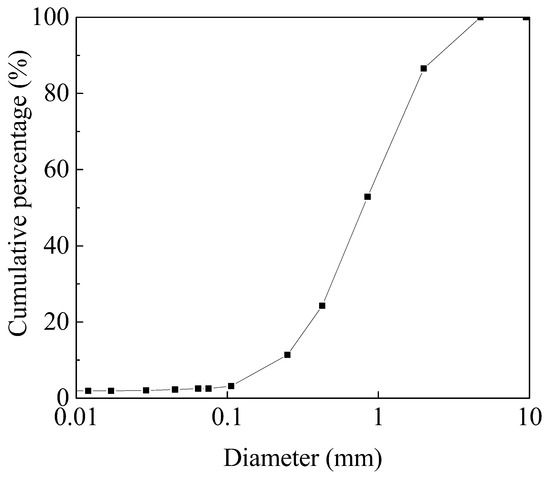
Figure 1.
Particle-size distribution of sand.
Bentonite is Na-bentoite obtained from the United States, which has low-permeability, good expansibility, high ion exchange capacity, as well as sufficient mechanical cushioning properties. Specific gravity is 2.76, plastic limit 38, liquid limit 581, plastic index 543, and cation exchange capacity 0.77 meq/g.
The content of bentonite is 10% (kg/kg, dry basis) of dry sand. Results of Proctor compaction tests (compaction energy = 592.2 kJ/m3) on bentonite-sand mixtures shows that the maximum dry density of sand is 1.60 g/cm3 with an optimal moisture content of 17.5%. The hydraulic conductivity is 8.99 * 10−7 cm/s at steady state by penetration test.
2.1.2. Geogrid
The geogrid with the thickness of 1.2 mm is made of high density polyethylene (Figure 2). It has a hole size of 15 mm and tensile strength of 7.6 kN/m.
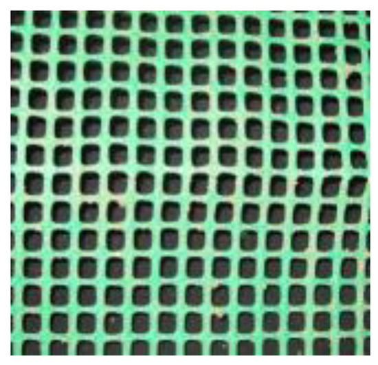
Figure 2.
Geogrid.
2.2. Apparatus
Experimental apparatus is shown in Figure 3. Low-permeability clay is used for laying in the model box, with length of 800 mm and width of 200 mm. A plastic pipe with holes is embedded just beneath the top of the bentonite-sand mixtures. The distilled water after infiltration is collected in the lower part of the apparatus. A rubber air bag is embedded on the top of soil, and hydraulic conductivity of low-permeability soil after local subsidence is obtained by adopting the Darcy’s law under constant head condition. The middle 400 mm is settlement area, which is controlled by Jack, with the displacement meter set on both sides. A rubber bag is placed on low-permeability soil, and uniform load is applied by filling air pressure. Tests are conducted to record settlement, deformation, load, and soil cracks.
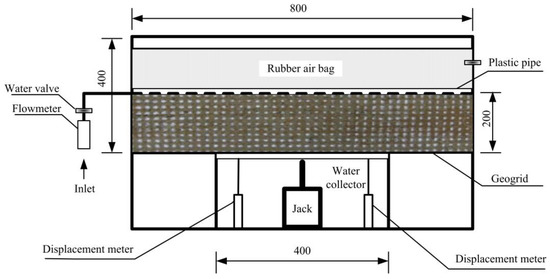
Figure 3.
Sketch of apparatus (all dimensions are in mm).
2.3. Test Procedure
2.3.1. Experimental Scheme
To observe the influence of soil thickness, geogrid, and upper load on the cracking and hydraulic conductivity of low-permeability soil, upper load is set constant at 147 KPa, with four schemes, as shown in Table 1.

Table 1.
Details of model tests.
2.3.2. Methods
Mixed soil is prepared with a bentonite mixing amount of 10% and water content 17.5%, and then compacted in three layers with more than 95% of compaction degree. As shown in Figure 4, the dimensions of specimens were: length 500 mm, height 100 (or 200), width 200 mm. Water pipes were placed on the soil, then with waterproof membrane laid above, and finally pressure rubber bags. A layer of bentonite is expanded on the contact surface between soil and model box wall, which swells with water and thus can seal the gap between the soil and model box wall to prevent leakage.
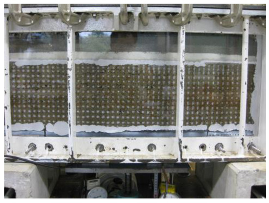
Figure 4.
Sample.
At the start of test, water valve was first opened, with water pressure maintained at 9.8 kPa, to observe water level and flow changes every 10 min. When the flow became stable and was then pressurized to the set load, Jack was falling at the speed of 0.5 mm/min until the set settlement. The designed settlements of bentonite-sand mixtures with thickness of 100 and 200 mm were 30 and 45 mm, respectively. Load, settlement, crack, and water flow were recorded during settlement. Deformation and cracking was analyzed through photographing marks that were set on the sides of soil.
3. Results and Discussion
3.1. Settlement and Crack Development
Soil cracked with lower settlement and first occurred on the settlement edge. The relationship between settlement and crack development is presented in Figure 5, which shows crack development on the right side. It can be seen that cracks of soil layer gradually develop from bottom to top with the increase of settlement. With soil thickness of 100 mm, cracks started when settlement was 2.5 and 3.5 mm, respectively, for bottom not laid and laid with geogrid. As settlement continued to increase, cracks became more serious from bottom to top along the height, accounting for 25%, 50%, 75% of total height, and even crack transfixion. Settlement was, respectively, 5, 12.5, 22.5, and 25 mm when not laid with geogrid, while 6.5, 14.5, 23, and 30 mm when otherwise. Test results for thick soil layer of 200 mm and 100 mm are similar, i.e., cracking accounted for 25%, 50% of total height, and even crack transfixion. Settlement was, respectively, 7, 18, 34.5, and 42.5 mm when not laid with geogrid, while 10.5, 20.5, 38, and 45 mm when otherwise.
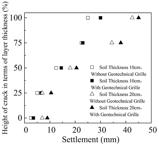
Figure 5.
Relationship between settlement and crack development.
According to experimental results, with equal soil thickness, the relationship between crack depth ratio and settlement fluctuates, but on the whole under the same ratio settlement is slightly larger when laid with geogrid than otherwise. The difference is likely due to that geogrid laid has an inhibiting effect on the bottom layer and thus results in delayed cracking. When compared under the same crack depth ratio, settlement value for soil layer of 200 mm is larger than that for 100 mm.
3.2. Crack Angle and Size
Soil cracks occur with the increase of settlement in the lower section, and the condition for soil thickness of 200 mm upon crack transfixion is shown in Figure 6. It can be seen that cracks occur on both sides of the subsidence area, which are in splayed shape, big on the top, while small on the bottom, with basically the same angle on the left and right side. Cracks development and angle are shown in Table 2.
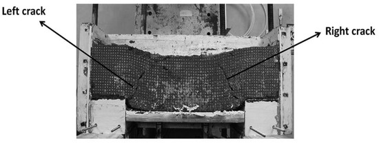
Figure 6.
Picture of sample after test.
Table 2.
Crack trend.
Table 2 records the angle between the crack and the height direction, showing that the angle is as small as about 40–45 degrees when cracks first occur whether or not being laid with geogrid and regardless of soil layer thickness. The angle increases with cracks development and reaches 60 degrees upon crack transfixion. When compared with a soil layer thickness of 100 mm, crack angle for soil layer thickness of 200 mm is slightly larger when the crack height is small. However, the results are basically the same when crack height becomes greater than 50% of soil thickness, indicating that soil thickness has little effect on fracture angle.
Similarly, soil bottom not laid with geogrid also has little effect on crack angle. It can be analyzed from digital camera images that with soil thickness of 100 mm and not laid with geogrid on the bottom, crack width is smaller than 1 mm at the start of cracking. With the increase of settlement, cracks in the lower section become larger, with crack width reaching 5 mm and 15 mm, respectively, when crack height is 50% of soil thickness and upon cracks transfixion. Crack development for soil thickness of 200 mm is similar to that for 200 mm, with a maximum width of 20 mm upon cracks transfixion.
With geogrid laid on the bottom, crack width remains smaller than 1mm from the occurrence of cracks to cracks developing upward along the height till crack development height reaching 50% of soil thickness. When settlement reaches 45 mm, crack width keeps around 3 mm, for soil thickness of both 100 mm and 200 mm.
3.3. Settlement and Hydraulic Conductivity
Settlement and Hydraulic Conductivity
The relationship between settlement and hydraulic conductivity is presented in Figure 7, Figure 8, Figure 9 and Figure 10. As shown in Figure 7 and Figure 8, with soil thickness of 100 mm, whether or not being laid with geogrid on the bottom, hydraulic conductivity is as big as 10−5–10−6 cm/s at the start of watering and before the occurrence of cracking. With infiltration time prolonging, bentonite swelling in the soil filled the space between particles and hydraulic conductivity decreased. After watering for 100 h, hydraulic conductivity of soil was reduced to 10−7 cm/s level, or to even lower level of 10−8 cm/s, which meets the penetration requirements as impermeable layer. As the foundation settled, bentonite-sand mixtures started to deform and cracks appeared and exceeded 25% of the bentonite-sand mixtures thickness when the bentonite-sand mixtures without geogrid reinforcement settlement was 10 mm. The hydraulic conductivity increased from 10−8 cm/s to about 5 × 10⁻⁷ cm/s, because cracks were formed at the bottom of the bentonite-sand mixtures without geogrid reinforcement and negatively impacted permeability. With settlement over 20 mm, bottom cracks developed upward rapidly and formed crack transfixion, thus losing impermeability. As shown in Figure 8, relationship between variation of settlement and hydraulic conductivity was similar whether or not laid with geogrid. With settlement of 15 mm, crack height was about 50%, with hydraulic conductivity ranging between 5 × 10⁻⁷ cm/s and 10−6 cm/s. However, when the settlement was over 30 mm, hydraulic conductivity could still reach 10−6 cm/s level, and crack transfixion occurred after 150 min, with the breaking of soil layer and the loss of impermeability.
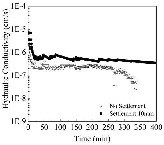
Figure 7.
Time and hydraulic conductivity (soil thickness100 mm; without geogrid).
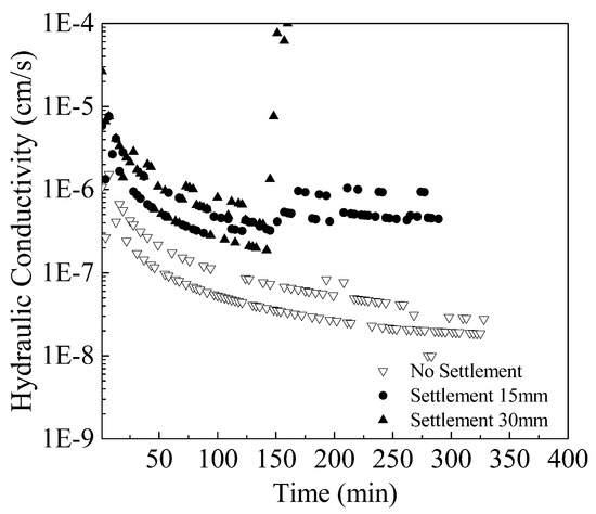
Figure 8.
Time and hydraulic conductivity (soil thickness 100 mm; with geogrid).
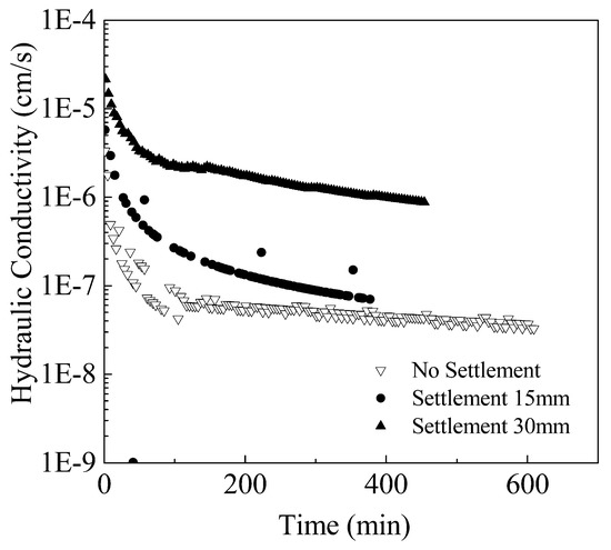
Figure 9.
Time and hydraulic conductivity (soil thickness 200 mm; without geogrid).
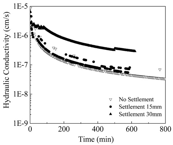
Figure 10.
Time and hydraulic conductivity (soil thickness 200 mm; with geogrid).
With soil thickness of 200 mm and whether or not being laid with geogrid, relationship between settlement and hydraulic conductivity was similar, as shown in Figure 9 and Figure 10. After 400 min of infiltration and without foundation settlement, hydraulic conductivity was kept at about 5 × 10⁻⁸ cm/s. With 15 mm of settlement, hydraulic conductivity was about 8 × 10⁻⁸ cm/s and 7 × 10⁻⁸ cm/s, respectively, when being laid with and without geogrid, which was very close mainly due to that crack height did not reach 50% of soil sickness with crack width less than 1 mm, thus having little effect on hydraulic conductivity. With further increase of settlement, cracks extended upward with increased width. When settlement reached 30 mm, crack height was close to 70% of soil thickness, with only about 60 mm uncracked and a maximum width of over 5 mm, which led to decreased hydraulic conductivity, being 2 × 10⁻⁷ cm/s and 7 × 10⁻⁷ cm/s, respectively, when being laid with and without geogrid. With settlement exceeding 40 mm, crack transfixion gradually occurred, and thus lost impermeability.
4. Conclusions
Based on the analysis and interpretation of the model test results, the following conclusions can be drawn when the length of the settlement area was is relatively close to the thickness of the bentonite-sand mixtures:
- (1)
- Bentonite-sand mixtures reinforced with geogrid restrained carcking better. Un-reinforced bentonite-sand mixtures of 100 mm and 200 mm thickness were observed to begin cracking at settlement levels of 2.5 mm and 7 mm, respectively. The bentonite-sand mixtures of 100 mm and 200 mm thickness with geogrid reinforcement were observed to begin cracking at settlement levels of 3.5 mm and 9 mm, respectively. When settlement reached 25 and 42.5 mm, cracks for 100 mm and 200 mm thick bentonite-sand mixtures without geogrid being penetrated completely. Moreover, cracks for 100 mm and 200 mm thick bentonite-sand mixtures without geogrid penetrated completely when settlement reached 30 and 45 mm.
- (2)
- Bentonite-sand mixtures reinforced with geogrid restrained carck width better. The maximum crack width for 100 mm and 200 mm thick bentonite-sand mixtures unreinforced with geogrid was found be 15 mm and 20 mm. The cracks of bentonite-sand mixtures reinforced with geogrid were <1 mm in width when the crack approached 50% of the layer thickness. When settlement reached maximum settlement, crack width kept around 3mm no matter whether the crack thickness was 100 mm or 200 mm.
- (3)
- The settlement levels for bentonite-sand mixtures of 100 mm thickness with and without geogrid reinforcement was found to be 10 mm and 15 mm, respectively, when its hydraulic conductivity was around 5 × 10⁻⁷ cm/s. With the crack approaching 70% of the layer thickness, the hydraulic conductivity of bentonite-sand mixtures with and without geogrid reinforcement increased to 2 × 10⁻⁷ cm/s and 7 × 10⁻⁷ cm/s, respectively.
- (4)
- The effect of geogrid on development of crack angle of bentonite-sand mixtures is little. Angle of the cracks just initiated was relatively small, at around 40–45°. The angle increased gradually as the crack continued to grow, with angle of the penetrating crack at about 60°.
Author Contributions
S.X., J.L. and H.Z. conceptualized the study and designed the experiments. C.L., M.B. and W.W. performed the experiments. C.L., S.X. and Z.W. acquired, collected and analyzed the data in the experiments. C.L. and S.X. co-wrote the paper.
Funding
The authors gratefully acknowledge the support from Natural Science Foundation of Zhejiang Province (grant numbers: Y14E080049, LY15E080021), Postdoctoral Scholarships of Zhejiang Province (grant number: BSH13020) and Project 51778585 supported by Natrual Science Foundation of China.
Conflicts of Interest
The authors declare no conflict of interest.
References
- China Architecture & Building. 2012 Technical Code for Geotechnical Engineering of Municipal Solid Waste Sanitary Landfill; CJJ 176–2012; China Architecture & Building Press: Beijing, China, 2012. [Google Scholar]
- Albrecht, B.; Benson, C. Effect of desiccation on compacted natural clays. J. Geotech. Geoenviron. Eng. 2001, 127, 67–75. [Google Scholar] [CrossRef]
- Krisnanto, S.; Rahardjo, H.; Fredlund, D.G.; Leong, E.C. Water content of soil matrix during lateral water flow through cracked soil. Eng. Geol. 2016, 210, 168–179. [Google Scholar] [CrossRef]
- Ling, D.; Xu, Z.; Cai, W.; Wang, Y. Experimental study on characteristics of bending cracks of compacted soil beams. Chin. J. Geotech. Eng. 2015, 37, 1165–1172. [Google Scholar] [CrossRef]
- Cai, W.; Ling, D.; Xu, Z.; Chen, Y. Influence of preferential flow induced by a single crack on anti-seepage performance of clay barrier. Rock Soil Mech. 2014, 7598, 2838–2845. [Google Scholar]
- Vo, T.D.; Pouya, A.; Hemmati, S.; Tang, A.M. Numerical modelling of desiccation cracking of clayey soil using a cohesive fracture method. Comput. Geotech. 2017, 85, 15–27. [Google Scholar] [CrossRef]
- Zhang, B.; Li, Q.; Yuan, H.; Sun, X. Tensile Fracture Characteristics of Compacted Soils under Uniaxial Tension. J. Mater. Civ. Eng. 2015, 27. [Google Scholar] [CrossRef]
- Chen, X.; Zhang, J.; Li, Z. Shear behaviour of a geogrid-reinforced coarse-grained soil based on large-scale triaxial tests. Geotext. Geomembr. 2014, 4, 312–328. [Google Scholar] [CrossRef]
- Zhang, Y.; Wang, H.M.; Yan, L.F. Test research on tensile properties of compacted clay. Rock Soil Mech. 2013, 34, 2151–2157. [Google Scholar]
- Zhang, Y.; Zhang, B.Y.; Li, G.X.; Sun, X. Combined tension-compression triaxial tests and extended Duncan-Chang model of compacted clay. Chin. J. Geotech. Eng. 2010, 32, 999–1004. [Google Scholar] [CrossRef]
- Dickinson, S.; Brachman, R.W.I. Deformations of a geosynthetic clay liner beneath a geomembrane wrinkle and coarse gravel. Geotext. Geomembr. 2006, 24, 285–298. [Google Scholar] [CrossRef]
- Sharma, H.D.; De, A. Municipal Solid Waste Landfill Settlement: Postclosure Perspectives. J. Geotech. Geoenviron. Eng. 2007, 133. [Google Scholar] [CrossRef]
- Gourc, J.P.; Camp, S.; Viswanadham, B.V.S.; Rajesh, S. Deformation behavior of clay cap barriers of hazardous waste containment systems: Full-scale and centrifuge tests. Geotext. Geomembr. 2010, 28, 281–291. [Google Scholar] [CrossRef]
- Viswanadham, B.V.S.; Rajesh, S. Centrifuge model tests on clay based engineered barriers subjected to differential settlements. Appl. Clay Sci. 2009, 42, 460–472. [Google Scholar] [CrossRef]
- Camp, S.; Gourc, J.P.; Ple, O. Landfill clay barrier subjected to cracking: Multi-scale analysis of bending tests. Appl. Clay Sci. 2010, 48, 384–392. [Google Scholar] [CrossRef]
- Viswanadham, B.V.; Jha, B.K.; Sengupta, S.S. Centrifuge Testing of Fiber-Reinforced Soil Liners for Waste Containment Systems. Pract. Period. Hazard. Toxic Radioact. Waste Manag. 2009, 13, 45–58. [Google Scholar] [CrossRef]
- Plé, O.; Manicacci, A.; Gourc, J.P.; Camp, S. Flexural behaviour of a clay layer: Experimental and numerical study. Can. Geotech. J. 2012, 49, 485–493. [Google Scholar] [CrossRef]
- Viswanadham, B.V.S.; Jessberger, H.L. Centrifuge Modeling of Geosynthetic Reinforced Clay Liners of Landfills. J. Geotech. Geoenviron. Eng. 2005, 131, 564–574. [Google Scholar] [CrossRef]
- Viswanadham, B.V.S.; Muthukumaran, A.E. Influence of geogrid layer on theintegrity of compacted clay liners of landfills. Soils Found 2007, 47, 519–534. [Google Scholar] [CrossRef]
- Melchior, S.; Sokollek, V.; Berger, K.; Vielhaber, B.; Steinert, B. Results from 18 Years of In Situ Performance Testing of Landfill Cover Systems in Germany. J. Environ. Eng. 2010, 136, 815–823. [Google Scholar] [CrossRef]
- Hettiarachchi, H.; Meegoda, J.; Hettiaratchi, P. Effects of gas and moisture on modeling of bioreactor landfill settlement. Waste Manag. 2009, 29, 1018–1025. [Google Scholar] [CrossRef] [PubMed]
- Hirobe, S.; Oguni, K. Coupling analysis of pattern formation in desiccation cracks. Comput. Methods Appl. Mech. Eng. 2016, 307, 470–488. [Google Scholar] [CrossRef]
- Zhu, H.; He, X.; Wang, K.; Su, Y.; Wu, J. Interactions of vegetation succession, soil bio-chemical properties and microbial communities in a Karst ecosystem. Eur. J. Soil Biol. 2012, 51, 1–7. [Google Scholar] [CrossRef]
- Albright, W.H.; Benson, C.H.; Gee, G.W.; Abichou, T.; Tyler, S.W.; Rock, S. Field performance of a compacted clay langfill final cover at a humid site. J. Geotech. Geoenviron. Eng. 2006, 132, 1393–1403. [Google Scholar] [CrossRef]
- He, J.; Wang, Y.; Li, Y.; Ruan, X. Effects of leachate infiltration and desiccation cracks on hydraulic conductivity of compacted clay. Water Sci. Eng. 2015, 8, 151–157. [Google Scholar] [CrossRef]
- Kodikara, J.; Costa, S. Desiccation Cracking in Clayey Soils: Mechanisms and Modelling; Multiphysical Testing of Soils and Shales; Laloui, L., Ferrari, A., Eds.; Springer: Berlin/Heidelberg, Germany, 2013; pp. 21–32. [Google Scholar]
- Gui, Y.L.; Zhao, Z.Y.; Kodikara, J.; Bui, H.H.; Yang, S.Q. Numerical modelling of laboratory soil desiccation cracking using UDEC with a mix-mode cohesive fracture model. Eng. Geol. 2016, 202, 14–23. [Google Scholar] [CrossRef]
- Sima, J.; Jiang, M.; Zhou, C. Numerical simulation of desiccation cracking in a thin clay layer using 3D discrete element modeling. Comput. Geotech. 2014, 56, 168–180. [Google Scholar] [CrossRef]
- Wang, D.Y.; Tang, C.S.; Cui, Y.J.; Shi, B.; Li, J. Effects of wetting-drying cycles on soil strength profile of a silty clay in micro-penetrometer tests. Eng. Geol. 2016, 206, 60–70. [Google Scholar] [CrossRef]
- Tang, C.S.; Wang, D.Y.; Shi, B.; Li, J. Effect of wetting-drying cycles on profile mechanical behavior of soils with different initial conditions. Catena 2016, 139, 105–116. [Google Scholar] [CrossRef]
© 2018 by the authors. Licensee MDPI, Basel, Switzerland. This article is an open access article distributed under the terms and conditions of the Creative Commons Attribution (CC BY) license (http://creativecommons.org/licenses/by/4.0/).