Abstract
Implant science has traditionally treated “biocompatibility” as the master criterion of success, focusing on cytotoxicity, corrosion, immune response, infection control, and the chemical stability of materials in vivo. However, many clinically “biocompatible” devices still fail at the point where the body actually meets the device: the mechanical interface. The interface is not a passive boundary. It is a living, adapting, mechanosensitive microenvironment in which cells integrate stiffness, micromotion, surface roughness, fluid shear, and wear debris with biochemical signals to decide whether to incorporate an implant, wall it off, resorb adjacent tissue, or trigger chronic inflammation. In load-bearing orthopaedics, stiffness mismatch produces stress shielding and maladaptive remodelling; excessive micromotion drives fibrous encapsulation rather than osseointegration; abrasive wear creates particulates that sustain macrophage activation and osteolysis; and design choices that are mechanically adequate in bench tests can still fail in vivo when the implant–tissue system evolves. In soft-tissue implantation, substrate stiffness can be a primary driver of the foreign body response and fibrotic capsule formation through mechanosensitive pathways, such as TRPV4-mediated macrophage–fibroblast signalling. Mechanical compatibility is not a replacement for classical biocompatibility; rather, it should be treated as a co-equal, first-class design requirement in mechanosensitive organisms. Chemically biocompatible materials can still fail through stiffness mismatch, micromotion, fretting and wear debris generation, and mechanobiology-driven fibrosis or osteolysis. We therefore propose a process view of implant success: tissue mechanics should be measured in clinically relevant states, transformed into constitutive models and interface performance envelopes, translated into explicit mechanical-compatibility specifications, and then realised through manufacturing process windows that can reliably reproduce targeted architectures and surface states. Additive manufacturing and microstructural engineering enable the tuning of modulus, the formation of porosity gradients, and the generation of patient-specific compliance fields, but these advances only improve outcomes when coupled to metrology, statistical process control, and validation loops that close the gap between intended and realised interface mechanics through clinical surveillance.
1. Introduction: Why the Interface Is Where Implants Succeed or Fail
The past half-century of biomaterials research has produced an impressive library of “biocompatible” materials: titanium alloys for skeletal fixation, cobalt–chromium for high-wear bearings, ceramics for low-wear articulations, polymeric liners for low-friction motion, and hydrogels and silicones for soft-tissue applications. These materials have enabled millions of procedures and transformed quality of life. However, the persistence of revision surgery, late loosening, fibrous encapsulation, and mechanically mediated inflammation indicates that chemical compatibility alone does not determine clinical longevity. In total hip replacement, for example, failure modes include stress shielding and periprosthetic bone loss, aseptic loosening associated with interface mechanics, and adverse responses to wear debris [1]. These are not rare corner cases but recurring mechanisms that sit squarely at the mechanical interface. In soft tissue implantation, the foreign body response (FBR) remains a major cause of device dysfunction and clinical complications; importantly, implant stiffness itself can modulate the severity of FBR independent of biochemical cues, with stiff implants promoting collagen deposition, myofibroblast accumulation, and foreign body giant cells [2,3,4,5,6].
The core claim of this article is therefore simple but consequential: mechanical compatibility is the new biocompatibility. Here, “new” is used to emphasise priority and traceability, not to displace established chemical and biological safety requirements; mechanical compatibility is treated as a co-equal design pillar that must be specified, controlled, and validated across the lifecycle. Mechanical compatibility refers to the degree to which an implant’s stiffness, compliance distribution, damping, frictional behaviour, and interfacial micromotion fit the mechanics of the host tissue and the evolving biomechanical environment over the device’s life. This is not merely a philosophical reframing. It implies that the specification set for an implant must include explicit, measurable mechanical interface requirements, and that these requirements must be traceable through manufacturing, quality assurance, and post-market surveillance in the same way that chemical and biological safety are now traced.
A process view is essential because “compatibility” is not a single number; it is an emergent property of a coupled system. The implant’s bulk material, microstructure, surface state, and geometric architecture are products of manufacturing processes. These processes introduce variability, residual stresses, anisotropy, and defects that change fatigue performance and interface behaviour. Meanwhile, tissue properties are heterogeneous, nonlinear, viscoelastic, and remodel over time. The interface is therefore a system-of-systems problem: a manufacturing process produces a device that is inserted into a living, adapting process. Design must therefore be linked to process control and validation loops.
Biomedical engineers have long used constitutive modelling to translate tissue tests into parameters and design insights. Recent biomechanical work in soft tissues illustrates why this translation is indispensable. For instance, ref. [7] quantified biaxial passive myocardial properties in the pig heart and calibrated parameters for the Holzapfel–Ogden constitutive model, showing how controlled mechanical testing can yield material constants for computational prediction. Ref. [7] advanced a biventricular finite element framework to study right-ventricular overload in the rat heart, demonstrating that organ-scale responses are tightly coupled to regional mechanics and loading. Ref. [8] further showed that local pathological remodelling (fibrotic infarction) in the left-ventricular free wall could alter the mechanics of otherwise healthy septal tissue during filling. Although these studies focused on cardiac mechanics rather than implants, they exemplify the broader point: tissue mechanics are spatially variable and state-dependent, and therefore the interface design cannot assume a single “textbook” modulus or a static target. If we can build computationally grounded pipelines from tissue test data to organ-scale mechanics, we can and should build analogous pipelines from tissue mechanics to implant interface design and manufacturing targets.
The remainder of the article develops this thesis in eight steps. First, it critiques the historical primacy of biocompatibility and shows why it is necessary but insufficient. Second, it formalises the implant–tissue interface as a mechanobiological boundary layer. Third, it analyses canonical failure modes driven by stiffness mismatch, micromotion, wear, and fibrosis. Fourth, it proposes mechanical-compatibility specifications as a structured deliverable for the design. Fifth, it explains how tissue mechanics can be measured and modelled to derive interface design envelopes. Sixth, it describes manufacturing levers, such as mainly additive manufacturing, porosity grading, and surface processing, through which these envelopes can be achieved. It defines the notion of process windows for interface properties. Seventh, it outlines validation and governance workflows that close the loop between design intent and clinical reality. Finally, it identifies practical research and standardisation opportunities that can make “mechanical compatibility” an implementable norm rather than an aspirational slogan.
2. From “Biocompatibility” to “Mechanobiocompatibility”: A Necessary Expansion of the Safety Concept
Biocompatibility has been foundational in biomaterials science because early failures were often chemical and immunological. Toxic monomers, corrosion products, and uncontrolled inflammatory responses demanded systematic biological evaluation. This history is reflected in standards and regulatory guidance. The ISO 10993 series [9], and ISO 10993-1 [10] in particular, provides a framework for the biological evaluation of medical devices within a risk-management process, emphasising endpoints such as cytotoxicity, sensitisation, irritation, systemic toxicity, genotoxicity, implantation response, and haemocompatibility. Regulatory agencies such as the U.S. FDA provide guidance for using ISO 10993-1 to support biological evaluation in device submissions [10]. These frameworks have improved safety and reduced the frequency of chemically driven catastrophes.
However, the dominant standards logic implicitly treats mechanics as an engineering performance topic rather than a biocompatibility topic. In practice, device developers test strength, fatigue life, and wear for functional performance, while biological evaluation is treated as a separate track. This separation is increasingly misaligned with modern mechanobiology. Cells do not divide their world into “chemical” and “mechanical” categories. Mechanotransduction pathways, including integrin-mediated adhesion, cytoskeletal tension, ion-channel activation, and nuclear mechanosensing, translate mechanical cues into gene expression and phenotype. The result is that mechanics can directly produce “biological” outcomes such as fibrosis, inflammation, or tissue loss. The TRPV4-mediated stiffness-induced foreign body response provides a direct example: implant stiffness can regulate macrophage fusion into foreign body giant cells and promote fibrotic capsule formation, and TRPV4 deficiency reduces collagen deposition and inflammatory cell accumulation around stiff but not soft implants [2,6]. In other words, stiffness can act as a primary determinant of biological compatibility in vivo.
The orthopaedic literature provides analogous examples in a hard-tissue context. Stress shielding is typically described as a mechanical phenomenon: a stiff implant carries load, reducing strain energy in adjacent bone, and thereby stimulating resorption. However, the clinical manifestation is bone loss—a biological remodelling response. Adaptive remodelling models and finite element simulations show that material modulus and boundary conditions can shift both the predicted bone resorption and interface stresses, with trade-offs between reduced stress shielding and increased interface stress that may threaten fixation [11]. Long-term clinical observations and modelling thus show how mechanics and biology cannot be cleanly separated. A similar coupling exists for wear debris: particulate matter from mechanical abrasion triggers macrophage activation, cytokine release, and osteolysis, which can lead to aseptic loosening [1]. “Wear” is therefore not merely tribology; it is an immunomechanical process.
These insights motivate an expanded concept of compatibility that we might call mechanobiocompatibility: compatibility that recognises that mechanical cues are not neutral inputs but active biological signals. In mechanobiocompatibility, the design problem includes not only avoiding toxicity, but also ensuring that mechanical cues fall within ranges that promote desirable tissue integration. This can be operationalised by defining interface performance envelopes: ranges of micromotion, strain transfer, shear stress, and stiffness gradients associated with stable integration, and then designing and manufacturing these to remain within these envelopes over time.
The concept also clarifies why “biocompatible but mechanically incompatible” devices can fail. Titanium is chemically compatible and widely used in implants, but dense titanium’s modulus is far higher than that of bone, leading to stress shielding if not architected appropriately. Similarly, cobalt–chromium is wear-resistant but stiff and can create adverse load distributions. Conversely, low-modulus materials can reduce stress shielding but may increase interface stresses and micromotion depending on design and fixation, risking disruption [11]. The central lesson is that mechanical compatibility is a constrained optimisation problem; it cannot be solved by material selection alone. It requires an integrated pipeline from tissue mechanics to design targets to controlled processes.
3. The Implant–Tissue Interface as a Living Boundary Layer
Mechanical compatibility becomes actionable when we treat the interface as a boundary layer with its own mechanics, biology, and process history. The “interface” is not simply a geometric contact surface but a region that includes microtopography, interstitial fluid, nascent tissue ingrowth or fibrous encapsulation, and the evolving distribution of contact pressure and shear. In porous implants, the interface consists of a transition zone where tissue grows into pores, creating a composite region whose effective stiffness evolves. In soft-tissue implants, the interface often forms a capsule whose thickness and stiffness can change over time. In both cases, the interface is where load transfer, friction, fluid transport, and immune surveillance coexist.
Three features of interface mechanics are essential.
First, tissue mechanics are nonlinear and heterogeneous. Many tissues display anisotropy, viscoelasticity, and regional variation in stiffness and strength. Cardiac tissue, for example, exhibits direction-dependent stiffness captured by fibre-reinforced constitutive models such as Holzapfel–Ogden; biaxial tests and model calibration show how material constants can differ across regions and conditions [12,13,14]. Such heterogeneity is not unique to the heart; bone varies between cortical and trabecular regions, and soft tissues vary by collagen architecture and hydration. This matters because implants are placed into specific areas, not into average tissue.
Second, tissues remodel in response to altered mechanical environments. In bone, remodelling can increase or decrease density depending on the strain energy distribution, and simulation studies demonstrate that implant material properties can dramatically shift the predicted resorption patterns [6]. In soft tissue, increased stiffness can promote myofibroblast differentiation and collagen deposition; in the context of implanted materials, stiffness-dependent FBR can stiffen the pericapsular region itself, potentially creating a feedback loop [2]. The interface therefore evolves, and mechanical compatibility must consider trajectories, not only the initial states.
Third, manufacturing processes imprint the surface and subsurface in ways that matter biologically. Additive manufacturing by powder bed fusion produces characteristic surface roughness, adhered particles, and microstructural anisotropy. In porous Ti–6Al–4V structures manufactured by laser powder bed fusion, high surface roughness and partially melted particles persist even after cleaning, and dimensional deviations from CAD models depend on build direction and overhang geometry [15,16,17,18]. These features affect not only fatigue, but also cell attachment and potentially wear particle generation. Thus, interface performance is tied to process history.
A process view therefore implies the following: mechanical compatibility is not just “matching modulus”, but ensuring that the manufacturing process produces a reproducible interface phenotype that interacts with tissue mechanobiology in predictable ways. The interface phenotype includes macro-geometry for load transfer, meso-architecture for compliance gradients and ingrowth, microtopography for cell adhesion and friction, and microstructure for fatigue and corrosion resistance. Each phenotype element has associated process controls and metrology, and each must be linked to the tissue mechanics and clinical use-case.
4. Canonical Mechanical-Interface Failure Modes
4.1. Stiffness Mismatch and Stress Shielding: When Strength Is Not the Same as Compatibility
Stress shielding is often introduced as a consequence of placing a stiff element in parallel with a compliant biological structure. In the femur, a stiff stem can carry load that would otherwise be borne by bone, reducing the local stimulus and leading to bone resorption. Finite element-based remodelling simulations show that uncemented cobalt–chromium stems can be associated with high predicted proximal bone resorption, while “isoelastic” low-modulus stems can reduce resorption but elevate proximal interface stresses, creating a design conflict between remodelling preservation and interface integrity [11,19,20,21]. The clinical implication is that material stiffness and implant geometry must be co-designed with a fixation strategy to avoid both stress shielding and destabilising interface stresses.
More recent design strategies aim to reduce effective stiffness while preserving strength. Porous metals, lattice structures, and composite stems (including carbon fibre reinforced polymers) target lower effective modulus and improved proximal load transfer. However, these strategies introduce new challenges: porous structures can reduce stiffness but may reduce fatigue strength and increase notch sensitivity; composites can introduce new failure modes at modular interfaces; and low stiffness may increase micromotion if fixation is not sufficient. A mechanical-compatibility specification must therefore include both stiffness matching and stability criteria.
4.2. Micromotion: A Threshold Phenomenon with Biological Consequences
Bone ingrowth and stable osseointegration require a mechanical environment that supports vascularisation, cell migration, and matrix deposition. Excessive micromotion at the interface can disrupt early tissue formation and encourage fibrous tissue rather than bone. A systematic review of micromotion-based reconstruction in bone–implant interfaces summarises an evidence base suggesting that micromotion ranges on the order of tens of micrometres support bone formation, while larger micromotions are associated with fibrous tissue formation and reduced osseointegration [20]. The experimental and clinical literature often converge on approximate thresholds (for example, around 150 μm) above which fibrous encapsulation becomes more likely, although the threshold can vary with surface, pore geometry, and loading regime [22]. These values should not be treated as universal constants but as design anchors that define an interface stability envelope.
Micromotion is also a process variable, not merely a design parameter. Surgical technique, press-fit, bone quality, and early postoperative loading determine micromotion trajectories. The same implant can be stable in one patient and unstable in another. Thus, mechanical compatibility implies designing for robust stability under uncertainty: the implant should remain within the micromotion envelope across plausible ranges of bone density, surgical placement, and early activity. This is where probabilistic modelling and digital verification become critical.
Figure 1 makes explicit that mechanical compatibility is multi-constraint: an implant can be “strong enough” but still fail if mismatch-driven stress shielding and micromotion-driven instability push the interface outside a viable envelope. This motivates the shift from qualitative mechanism descriptions to measurable specification channels, which are then operationalised, as testable interface metrics and acceptance logic.
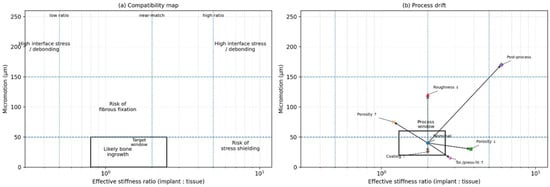
Figure 1.
Interface compatibility map and process drift. (a) A two-axis plot relating effective stiffness ratio (implant:tissue; log scale) to cyclic micromotion amplitude at the interface. Regions may be interpreted as elevated risk zones for fibrous fixation (higher micromotion), stress shielding (higher stiffness ratio under low micromotion), and high interface stress/debonding at extreme mismatch. Example micromotion anchors from the literature are often reported in the tens of micrometres for bone ingrowth (e.g., ~28 μm) and above ~150 μm for increased likelihood of fibrous membrane formation (see [22]). (b) Schematic “process window” illustrating how manufacturing and implantation variability can move a nominal design away from the intended compatibility region. Arrow meanings: Porosity ↑/↓ → changes stiffness ratio and micromotion, Roughness ↓ → affects interface mechanics and stability, Coating ↑ → modifies interface compliance and bonding, Tolerance/press-fit ↑ → alters micromotion behavior, post-process → combined effects shifting the system state.
4.3. Wear, Abrasion, and Tribo-Inflammation: Mechanical Particles as Biological Triggers
Articulating implants and modular junctions generate wear debris through abrasion, adhesion, and fatigue wear. In hip arthroplasty, wear debris propagation is widely recognised as a leading cause of component loosening and adverse tissue reactions [1,23,24]. The particulate load activates macrophages and can drive chronic inflammatory signalling and osteolysis. Mechanical compatibility therefore includes tribological compatibility: the implant must minimise wear generation and control the size, chemistry, and volume of particles. This is not limited to bearing couples; even porous surfaces can generate particles through fretting at microcontacts if micromotion persists. Process-induced surface roughness and adhered powder particles in additively manufactured implants may therefore be relevant if they detach under cyclic loading [5]. Designing for mechanical compatibility requires explicit attention to wear mechanisms at both macro- and micro-scales.
4.4. Fibrosis and Encapsulation: Stiffness as an Immunomechanical Cue in Soft Tissue
Soft tissue implants, sensors, and drug-delivery devices frequently fail because the body forms a fibrous capsule that isolates the implant from its intended biological function. A key mechanobiological insight is that stiffness itself can modulate this capsule response. In a subcutaneous implantation model using polyacrylamide gels tuned from soft (~1 kPa) to rigid (~50 kPa), stiff implants promoted substantially higher collagen deposition and the accumulation of macrophages, foreign body giant cells, and myofibroblasts; TRPV4 was specifically required for stiffness-induced FBR, and TRPV4 deficiency reduced collagen deposition around stiff implants [21]. This result illustrates that “biocompatible chemistry” does not guarantee integration; mechanical cues can be sufficient to trigger a pathological response.
For implant designers, the implication is twofold. First, mechanical compatibility must be considered even for devices that are not load-bearing in the classical engineering sense. Second, the effective stiffness sensed by cells is not only the bulk modulus, but also the surface compliance, coating thickness, and mechanics of the immediate microenvironment. A stiff implant with a compliant coating might present a softer mechanosensory interface, while a soft implant constrained by a stiff capsule may become functionally stiff. Therefore, compatibility specifications must include both intrinsic and effective stiffness at the interface, measured under conditions that mimic the in vivo constraint.
4.5. Pathological Tissue Mechanics: The Moving Target Problem
A final failure mode is conceptual rather than mechanical: designing for the wrong tissue. Tissue mechanics are not fixed; disease, age, and local remodelling shift properties. Ref. [13] showed that fibrotic infarction in one region of the heart can alter the mechanics of neighbouring “healthy” tissue, reflecting system-level coupling. Similarly, Masithulela’s ventricular modelling work showed that altered loading can change stress distributions and deformation patterns even when the tissue is nominally healthy [12]. Translating this to implants, bone quality changes with osteoporosis; soft tissue stiffness changes with fibrosis and diabetes; and local inflammation changes viscoelastic response. If mechanical compatibility is defined relative to “normal” tissue alone, implants may be mechanically mismatched for the patients who most need them. The process view therefore requires characterising target patient states and designing for a range of tissue property distributions.
5. Mechanical-Compatibility Specifications as First-Class Design Requirements
The central practical question is: how do we convert the abstract idea of mechanical compatibility into a design deliverable that can be verified, manufactured, and regulated? The answer is to define a mechanical-compatibility specification set that sits alongside the biological evaluation and classical mechanical strength requirements. This specification set should be interface-centric and expressed in measurable metrics with validated test methods.
A useful way to structure the specification is to treat the interface as a set of coupled “performance channels”:
Channel 1: Strain-transfer compatibility. The implant should transfer physiological loads to surrounding tissue in a way that avoids both stress shielding (under-stimulation) and overload (pathological strain concentrations). This channel is captured by metrics such as periprosthetic strain energy density distribution, load-sharing ratios, and predicted remodelling indices derived from finite element simulations. The early exemplar of such modelling demonstrated how material modulus shifts the remodelling outcomes and interface stresses [20].
Channel 2: Stability compatibility. The implant should maintain micromotion within a range that permits tissue integration and avoids fibrous encapsulation. This channel is described by peak micromotion under cyclic loading, cumulative slip over time, and the sensitivity of micromotion to variations in bone stiffness and press-fit. The evidence base synthesised by [19] and experimental measurement frameworks such as three-dimensional in vitro stability measurement [22] are relevant anchors for specification limits.
Channel 3: Tribological compatibility. The implant should minimise wear debris generation and avoid fretting at modular interfaces and microcontacts. Metrics include volumetric wear rates, particle size distributions, friction coefficients under simulated synovial environments, and fretting fatigue thresholds. Although wear is often tested for function, it should be elevated to compatibility status because of its direct immunological consequences [17].
Channel 4: Compliance and mechanosensory compatibility in soft tissue. For soft tissue devices, the effective stiffness presented to cells should be within ranges that minimise stiffness-induced inflammatory signalling and fibrotic encapsulation. The TRPV4 study indicates that stiffness differences in the kPa range can modulate FBR [3], suggesting that “mechanosensory modulus” may need to be specified separately from structural stiffness.
Channel 5: Fatigue compatibility under evolving boundary conditions. Many failures occur after the interface evolves—bone resorption, tissue ingrowth, or capsular formation changes loading. Compatibility therefore includes the robustness of fatigue life under plausible interface evolution, particularly for porous and additively manufactured structures where surface defects can dominate fatigue behaviour [5].
The novelty here is not that each channel is new, but that they are integrated into a coherent specification set with traceability. Instead of reporting micromotion, stress shielding, and wear as separate research outcomes, device development should treat them as acceptance criteria that manufacturing must meet.
Table 1 operationalises this approach by mapping key mechanical failure modes to specification metrics, test and modelling methods, and the primary process levers that can be used to achieve targets. The table is intended as a template rather than a universal standard; target values must be tailored by anatomy, patient population, and device type. The critical shift is institutional: compatibility metrics should appear in design inputs, design verification, and risk management files, and should be revisited when manufacturing changes occur.

Table 1.
Template mechanical-compatibility specification set (interface-centric).
6. From Tissue Mechanics to Design Targets: The Design-to-Interface Pipeline
If mechanical compatibility is to be specified, we need reliable methods to derive targets from tissue mechanics. This section outlines a pipeline that is deliberately parallel to mature workflows in structural engineering: materials testing to constitutive modelling to design allowables to process qualification. In biomedical design, the pipeline becomes: tissue test data to constitutive model to interface design targets to fabrication controls to validation loop.
Figure 2 provides a roadmap for the process view advanced in this manuscript. It links tissue characterisation and constitutive modelling to explicit interface targets (e.g., stiffness bands, micromotion limits), then carries these targets forward into fabrication controls, metrology, and bench validation, closing the loop through traceable updates when performance deviates from specification.
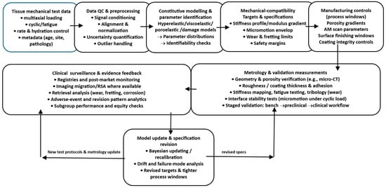
Figure 2.
Design-to-interface pipeline. A flow diagram showing tissue test data feeding a constitutive modelling stage, generating explicit mechanical-compatibility targets (stiffness profile, micromotion envelope, wear limits), which then map to manufacturing controls (porosity gradients, AM scan parameters, surface finishing windows) and to validation measurements, with a feedback loop to update models and specifications from metrology and clinical surveillance.
6.1. Tissue Mechanics Acquisition: Measuring What Matters
The first step is to measure tissue mechanics in states that match the implant context. For bone, this includes apparent density, anisotropic stiffness, and local strength. For soft tissues, it includes nonlinear stress–strain response, viscoelasticity, and fibre architecture. Importantly, tests should capture the relevant deformation modes and rates: compression and shear near bone–implant interfaces, tension and bending in ligaments, and multi-axial stretch in cardiovascular tissues.
Modern soft tissue biomechanics demonstrates why multi-axial testing is essential. Ref. [14] used biaxial testing to calibrate a fibre-reinforced constitutive law for passive myocardium, reflecting anisotropy and nonlinear stiffening. This type of approach is directly translatable to soft tissue implants: if we want a compliant coating or scaffold to mimic a tissue, we need multi-axial property targets, not only a uniaxial modulus. Similarly, Masithulela’s finite element modelling of biventricular mechanics illustrates how loading conditions can amplify or reduce regional strains [12], implying that implant design must consider the organ’s load environment, and not just isolated tissue coupons.
6.2. Constitutive Modelling: Translating Data into Predictive Parameters
Tissue data must be translated into constitutive models that can be used for simulation and design exploration. For bone, homogenised orthotropic elasticity linked to density may be sufficient for many applications. For soft tissues, fibre-reinforced hyperelasticity with viscoelastic extensions is often necessary. The purpose of modelling is not to create an academic description but to enable inverse design: given a target strain-transfer profile, what implant compliance field should be produced?
Nemavhola’s calibration of Holzapfel–Ogden parameters provides a concrete example of this translation: the model provides material constants that can be used in finite element models to predict tissue stress and strain under physiological deformation [13]. In an implant context, analogous models can be used to predict how a porous scaffold’s effective stiffness interacts with tissue to distribute stress, or how a compliant coating alters shear at the interface.
6.3. Design Targets: Defining Interface Envelopes Rather than Single Numbers
A key shift is to define envelopes. Because tissue properties vary, targets should be distributions or ranges. For a femoral stem, the target is not a single modulus but an effective stiffness profile along the stem that yields acceptable remodelling indices without excessive interface stress [11]. For porous structures, target ranges for pore size and porosity can be derived from both biological ingrowth requirements and mechanical strength requirements. Additive-manufactured porous Ti–6Al–4V structures with pore sizes in the 400–700 μm range can show mechanical properties within cortical and trabecular bone ranges and biological responses (cell morphology and ALP activity) that are relatively independent of pore size/shape within that range, suggesting a broad design space in which mechanical properties can be tuned without hefty biological penalties [25,27]. This supports the feasibility of graded porosity as a primary lever for mechanical compatibility.
Quantitative Compatibility Bands: What the Evidence Supports (and What Remains Device-Specific)
A compatibility framework becomes actionable when “envelopes” are anchored in quantitative evidence rather than asserted conceptually. While exact values are device-, anatomy-, and loading-specific, several ranges recur across the experimental biomechanics and clinical follow-up literature and can be treated as initial design anchors that must later be verified for the specific implant system. For example, interface micromotion under cyclic loading has repeatedly been shown to separate conditions that favour bone ingrowth from those associated with fibrous interposition, motivating the use of micromotion “bands” rather than single thresholds. Similarly, porous architecture variables such as pore size and porosity occupy a coupled design space: biological integration requires pores large enough for vascularised tissue ingrowth, while mechanical robustness and fatigue resistance constrain porosity and defect sensitivity.
Importantly, these anchors should be treated as priors in a Bayesian sense: they guide early design exploration and process-window selection but are refined using implant-specific validation (in vitro stability rigs, micro-CT defect statistics, fatigue testing under representative boundary conditions) and then further updated using early clinical signals (e.g., migration/stability and remodelling proxies). For this reason, the specification should explicitly record (i) the evidence basis for each band, (ii) the assumed loading scenario, and (iii) the uncertainty/heterogeneity expected across patients. Table 2 summarises example quantitative anchors that can be used to initialise compatibility envelopes before device-specific verification.
Table 2.
Evidence-anchored quantitative “compatibility bands” for initial specification (to be refined by device-specific verification and clinical feedback).
6.4. Bridging to Manufacturing: Design Targets Must Map to Controllable Process Parameters
Design targets must be tied to parameters that manufacturing can reliably control. In additive manufacturing, lattice geometry, strut thickness, scan strategy, energy density, and heat treatment influence porosity, surface roughness, microstructure, and residual stresses. Surface finishing, blasting, etching, and coating processes then modify the topography and chemistry. The process view demands explicit mappings: how does a change in laser energy density shift strut thickness variance and thus stiffness? How does building orientation change fatigue performance? How does a given post-processing route alter microcontact friction and wear debris generation? These mappings are the basis for the “surface process windows” and “architecture process windows” discussed in Section 7.
6.5. Validation Loop: Closing the Gap Between Intended and Realised Mechanics
Even with precise design, manufacturing variability and surgical variability can shift the interface mechanics. The pipeline must therefore include a validation loop that measures the realised properties and updates models and specifications. This is analogous to closed-loop quality systems in aerospace. In implants, the loop includes the metrology of pore size and roughness, mechanical testing of effective stiffness and fatigue, and in vitro or in vivo assays of integration where feasible. Importantly, clinical surveillance data can feed back into the pipeline: if certain patient populations experience higher loosening, tissue mechanics assumptions may be wrong, or process variability may be too high. The process view thus treats validation as continuous rather than as a one-off premarket activity.
7. Manufacturing for Mechanical Compatibility: Porosity Gradients, Modulus Tuning, and Surface Process Windows
Mechanical compatibility becomes practical only when we can reliably manufacture devices that embody specified compliance fields and surface states. This section focuses on three manufacturing levers that directly enable mechanical-compatibility specifications: architectural tuning through porosity and lattice design, functional grading to create compliance gradients, and surface processing to control friction, wear, and mechanosensory cues.
7.1. Architectural Tuning with Porous and Lattice Structures
Dense metals are mechanically mismatched to many tissues. Architectural porosity is therefore a primary lever for lowering effective stiffness while maintaining load-bearing capability. Additive manufacturing, especially the laser powder bed fusion of Ti–6Al–4V, enables controlled lattice architectures that can be tuned across a broad stiffness range. In a systematic experimental study, porous Ti–6Al–4V structures with pore sizes between 400 and 700 μm showed structural stiffness ranging approximately from 0.6 to 4.9 GPa depending on pore size and unit cell shape, overlapping ranges often associated with cortical and trabecular bone, and enabling the possibility of matching mechanical properties with gradient porosity [25,26,28]. The same study also reported process-linked surface roughness and dimensional deviations, reinforcing that architecture is inseparable from process.
The architectural design space includes unit cell type (diamond, cube, hexagon), strut thickness, connectivity, and porosity distribution. These choices not only affect stiffness, but also permeability and potential for vascularisation. The same study summarised the literature suggesting a minimum pore size on the order of 100 μm for blood vessel formation and that pore sizes above ~300 μm may enhance bone formation and vascularisation, though a broad optimum range exists rather than a single best value [29,30,31,32]. A process view therefore treats pore size as a coupled variable: it influences biological transport and mechanical stiffness simultaneously, and must be selected to satisfy both channels of compatibility.
7.2. Functional Grading: Why Porosity Gradients Are Not Optional
A persistent challenge in implant design is the trade-off between local compliance and global strength. If an entire implant is made highly porous to reduce stiffness, fatigue strength may be compromised. Functional grading provides a solution: make the interface region more porous (lower stiffness) while keeping the core denser (higher strength). In the porous titanium study, the authors explicitly proposed that the gradient porosity can achieve low stiffness at the bone–implant interface to reduce stress shielding while maintaining high overall strength [32,33,34,35,36,37,38]. This principle generalises across device types. A hip stem could have a compliant proximal region and a stronger distal core; a spinal cage could have a graded modulus to match endplate stiffness while resisting collapse.
Functional grading also enables “mechanical compatibility zoning”. Instead of designing one implant to be uniformly compatible, different regions can be tuned to the local tissue type. This is particularly relevant where cortical and trabecular bone coexist. The result is an implant that better matches the natural gradient architecture of bone.
7.3. Surface Process Windows: Topography and Compliance as Manufacturing Outputs
Surface roughness and chemistry influence osseointegration, but they also influence friction and micromotion. A rough surface can increase the initial stability by increasing frictional resistance to slip, potentially reducing micromotion. However, excessive roughness can also generate wear debris under micro-sliding. Additive manufacturing produces high inherent roughness, with adhered particles even after cleaning, which can affect both biological and mechanical behaviour [39,40,41,42]. The question is therefore not “rough or smooth” but “what surface state keeps the interface within the stability and wear envelopes for this application?”
The notion of a surface process window refers to the range of manufacturing parameters and post-processing steps that produce surface states meeting specifications. In powder bed fusion, scan parameters and powder size distribution influence the surface particle adhesion and roughness. Post-processing steps, such as hot isostatic pressing, machining, blasting, etching, and coating, then adjust the surface microtopography and remove loosely bound particles. The surface process window must therefore be specified and qualified, and changes to the process must be treated as design changes because they can shift interface friction, wear generation, and mechanosensory stiffness.
Surface Physicochemistry as a Co-Determinant of Interface Biology
Mechanical compatibility at the interface is expressed through biology, and therefore surface physicochemistry must be treated as a co-determinant rather than a secondary detail. Oxide chemistry, surface energy/wettability, and the nanometric structure of the oxide layer shape the identity and conformation of adsorbed proteins within minutes of implantation, which in turn controls the macrophage phenotype, osteogenic signalling, and the quality of tissue integration. Micro- and nano-topography interact with chemistry: the same roughness amplitude can produce different biological responses depending on oxide state, contamination, and hydrophilicity. Coatings (e.g., calcium phosphate/HA or functional polymer layers) add further coupled constraints because coating integrity becomes a mechanical variable: cracking, delamination, and third-body debris introduce wear particles and inflammatory triggers even when bulk materials remain “biocompatible”.
A compatibility-first framing therefore does not diminish classical surface science; it tightens it. Surface finishing and coating steps should be expressed as process windows with measurable outputs: roughness parameters, wettability/surface energy, chemical state (oxide composition/contaminants), and coating thickness/adhesion metrics where applicable. These outputs must then be tied back to the compatibility channels: roughness and chemistry affect early friction and stability (micromotion), they influence wear debris generation at microcontacts, and they modulate mechanosensing-driven foreign body responses in soft tissue. In short, a chemically acceptable material with poor stability or high debris generation can still fail, and a mechanically stable system with poor surface chemistry can also fail; compatibility requires both to sit inside validated envelopes.
7.4. Process Windows for Fatigue in Porous Structures
Porosity introduces stress concentrators and increases surface area, making fatigue a dominant design constraint. Effective fatigue performance depends on both architecture and process-induced defects. Powder bed fusion can introduce lack-of-fusion pores, surface notches, and residual stresses. Post-processing can reduce defects and improve fatigue, but can also alter microstructure and stiffness. A process view therefore requires that fatigue life be validated under conditions that represent the interface environment after implantation, including potential changes in load transfer as tissue integrates or resorbs. This is particularly important because compatibility-driven architectures may push materials closer to fatigue limits.
7.5. Soft Tissue Devices: Compliance Matching and Mechanosensory Coatings
In soft tissue applications, the manufacturing challenge shifts from load-bearing strength to mechanosensory tuning. The TRPV4 study suggests that stiffness differences in the kPa range can modulate FBR and collagen deposition [2,43,44]. Many device materials (silicones, polyurethanes, metals) are far stiffer than native soft tissues when considered at the microscale sensed by cells, particularly if constrained by device geometry. Manufacturing approaches such as soft coatings, hydrogel layers, and structured compliant surfaces can therefore be used to tune effective stiffness. Here, process windows include polymer crosslink density, hydration control, coating thickness, and interfacial adhesion. Mechanical compatibility becomes an explicit manufacturing output rather than a secondary property.
7.6. Manufacturing Traceability: From CAD to Clinic
To treat mechanical compatibility as first-class, the manufacturing system must provide traceability from design intent to realised device. In additive manufacturing, this implies linking CAD lattice parameters and porosity gradients to build parameters, in-process monitoring signals, and post-build metrology. For example, if a lattice region is designed for 2 GPa effective stiffness, the manufacturing system should demonstrate that realised strut thickness and pore size distribution produce that stiffness within tolerance, and that surface particle adhesion is within the limits to avoid debris. This is the operational meaning of “process view”: mechanical compatibility is not a narrative but a controlled variable [45,46,47,48] (Table 3).
Table 3.
Process-window translation: turning mechanical targets into controllable manufacturing variables.
Quantitative Process Windows: Linking LPBF Settings to Interface-Relevant Mechanical Properties
A “process view” requires parameter–property relationships that are not only conceptually plausible but also measurable and auditable, because interface stability and long-horizon failure modes (loosening, fretting wear, fatigue) are sensitive to manufacturing-driven variability. The design-to-manufacture link therefore benefits from reporting a minimal quantitative set of LPBF variables, laser power , scan speed , hatch spacing , and layer thickness , and a derived energy density that provides a first-order descriptor of melt-pool energy input [49,50,51,52]. While is not sufficient on its own (scan strategy, spot size, powder morphology, shielding gas, and thermal history matter), it is a useful auditable bridge between design intent (e.g., strut thickness and stiffness targets) and manufacturing control (Table 4).
In Ti–6Al–4V LPBF, shifts in energy input are strongly associated with defect regimes and surface integrity. Lower energy input increases the risk of lack-of-fusion defects, while excessive energy input can induce keyhole porosity, with distinct implications for fatigue and interface integrity [53,54,55]. Surface integrity likewise exhibits sensitivity to energy density; for example, reported Ti–6Al–4V builds spanning volumetric energy densities on the order of ~20–65 J·mm−3 demonstrate measurable changes in as-built surface condition and residual-stress/roughness characteristics across the window [56,57]. Because roughness and defect state influence crack initiation, fatigue performance can vary substantially across roughness regimes (e.g., Sa values in the single- to double-digit micron range), reinforcing that “compatibility-driven architectures” must be paired with validated process controls [58,59,60].
For interface-critical devices, the recommended practice is therefore to specify a quantitative process window (parameter ranges and acceptance thresholds), verify realised geometry and surface state (micro-CT and surface metrology), and tie these metrics to mechanical tests that correspond to specification channels (effective stiffness, micromotion/stability rigs, and representative fatigue/fretting tests), consistent with the manuscript’s validation-loop principle.
Table 4.
Quantified LPBF process-window examples (Ti–6Al–4V): parameter ranges and interface-relevant KPIs (illustrative, literature-reported).
Table 4.
Quantified LPBF process-window examples (Ti–6Al–4V): parameter ranges and interface-relevant KPIs (illustrative, literature-reported).
| Category | Variable (Auditable) | Representative Reported Ranges/Examples | Interface-Relevant KPI (What You Should Report/Accept) | Why It Matters for “Mechanical Compatibility” |
|---|---|---|---|---|
| Energy input descriptor | Defined relationship for LPBF energy density [49] | Report ED distribution by build region (dense vs. lattice), and associate with defect/roughness metrics | Links design targets to build control; supports traceability and change control | |
| Process window (example dataset) | Volumetric energy density (Ti–6Al–4V study example) | Example Ti–6Al–4V builds spanning ~21.7–65.4 J·mm−3 by varying power/speed [56] | Surface integrity/roughness metrics vs. ED; residual-stress consistency checks | Quantifies “surface process window” rather than describing it qualitatively |
| Defect regime mapping | Keyhole vs. lack-of-fusion propensity | Defect type depends on energy density regime [53,61] | Porosity type + size distribution (micro-CT/metallography); acceptance thresholds by region | Different defect regimes drive fatigue and debris risk differently |
| Surface condition to fatigue sensitivity | As-built roughness and fatigue response | Example: Sa ~7–15 µm range examined with fatigue performance differences [57] | Sa/Sz (or equivalent) + particle-adhesion checks; correlate with fatigue/fretting tests | Roughness drives crack initiation and can elevate wear debris generation |
| Mechanical behaviour mapping | Process parameters vs. tensile/roughness/porosity (Ti–6Al–4V) | Studies explicitly vary power/speed/hatch spacing and quantify strength/roughness/porosity [62,63]. | Report strength/stiffness scatter for manufacturing-representative coupons; link to build record | Converts “traceability” into measurable control evidence |
8. Verification, Validation, and Governance: Making Compatibility Deployable
Mechanical compatibility must be verifiable, clinically meaningful, and governable across the device lifecycle. This requires a validation ladder and a governance framework that integrates modelling, testing, and post-market learning.
8.1. Verification: Ensuring That Models and Tests Are Trustworthy
When finite element modelling is used to evaluate strain transfer, micromotion, and remodelling indices, verification is required: numerical stability, mesh convergence, sensitivity to material parameters, and boundary condition realism. The remodelling simulations in [11] illustrate both the utility and the sensitivity of such models: predicted resorption ranges can be large and depend on assumptions. Therefore, modern workflows should treat modelling as part of a quality system: version control of models, documented assumptions, and explicit uncertainty quantification where possible.
8.2. Validation Ladder: From Bench to Biology to Clinic
A pragmatic ladder begins with bench mechanical tests that directly correspond to specification channels. Compression and shear tests of porous structures can validate effective stiffness and strength; stability rigs can measure micromotion under cyclic loads [22]; tribology rigs can quantify wear and fretting. These tests should be performed not only on ideal samples, but on manufacturing-representative samples that include process variability.
The next rung involves biological plausibility tests: in vitro assays of cell adhesion and differentiation on surface states, and in vivo models where appropriate. Importantly, the biological endpoint must be connected to the mechanical variable. The TRPV4 study provides an exemplar: stiffness was tuned as the independent variable, and FBR outcomes were measured, demonstrating causality [2]. Similar designs are needed for orthopaedics: vary micromotion and measure osseointegration outcomes, vary architecture and measure remodelling, and vary surface particle adhesion and measure inflammation.
Clinical validation then requires outcome metrics linked to mechanical channels: radiographic remodelling patterns, migration and subsidence measures, revision rates for loosening, and biomarkers of inflammation where applicable. In hip implants, the complex interplay of stress shielding, micromotion, and wear is recognised as contributing to failure after 10–15 years [1,23,24]. Therefore, mechanical compatibility should be assessed with long-horizon surveillance, not only short-term endpoints.
8.3. Risk Management and Standards Integration
Compatibility specifications should be embedded in risk management. ISO 14971 provides a general risk management framework for medical devices; within this framework, mechanical incompatibility can be treated as a hazard leading to harms such as fracture, loosening, chronic inflammation, or functional failure. ISO 10993-1 situates biological evaluation within risk management, but the process view suggests that mechanical cues should also be treated as part of the biological risk, given mechanosensing-driven FBR [21]. FDA guidance emphasises risk-based biological evaluation and the use of ISO 10993-1 [10]. A coherent governance approach therefore links biological evaluation, mechanical verification, and manufacturing process control within a unified risk file.
8.4. Digital Traceability and the “Validation Loop” in Practice (Expanded)
Closing the loop between design intent, manufacturing realisation, and clinical performance requires more than a conceptual “digital twin”; it requires an implementable digital thread that links (i) tissue assumptions and interface envelopes, (ii) design targets and verification evidence, (iii) manufacturing build records and metrology, and (iv) post-market clinical signals. This operationalises the manuscript’s validation-loop principle that realised properties and outcomes should update models and specifications continuously.
A practical implementation can proceed in phases. First, device-level identification enables linkage between the implanted device and its production history across distribution and patient use; in the U.S. context, the FDA’s Unique Device Identification (UDI) system is explicitly intended to support lifecycle identification and modernise postmarket surveillance [64]. Second, build and quality records can be structured as an electronic device history record (eDHR/DHR conceptually) that stores the parameter set (e.g., scan strategy, energy density proxies), in-process monitoring summaries, post-build metrology (micro-CT pore/strut statistics; surface roughness/particle adhesion checks), and representative mechanical tests that map to the device’s compatibility specification channels (effective stiffness, fatigue, fretting/tribology). Third, post-operative follow-up should prioritise clinical variables that are interpretable as mechanical-channel proxies: early implant migration and inducible displacement (where feasible) have an evidence base as predictors of later loosening risk, and guidance frameworks exist for RSA/CT-RSA migration measurement and reporting [65,66].
Reverse iteration is achieved when these clinical signals trigger-controlled updates to engineering controls. For example, if a patient subgroup exhibits higher-than-expected early migration or characteristic remodelling patterns, the corrective actions can be traced to: (i) revising tissue assumptions and interface envelopes (micromotion/stability limits), (ii) updating design targets (porosity gradient slope, local stiffness bands, surface state requirements), and (iii) tightening manufacturing control limits (process window bounds, acceptance thresholds for strut-thickness deviation, porosity-type fraction, or roughness). A key requirement is governance: updates must follow design change control, with re-verification and re-validation steps and documentation in the risk-management file, so that post-market learning becomes auditable rather than anecdotal. In this sense, even a “modest” digital thread, without a full physiological twin, can deliver the core value: clinically grounded, traceable learning across the design-to-interface lifecycle [67,68].
Figure 3 synthesises the manuscript’s process view by visualising the closed-loop “digital thread” that links design, manufacturing, verification, and clinical learning into a single auditable pathway. The sequence begins with design intent (mechanical compatibility targets and interface envelopes), which is instantiated through build records and metrology that capture the as-built geometry, surface state, and defect/porosity metrics needed for traceability. These manufacturing artefacts feed bench validation, where tests aligned to specification channels (e.g., effective stiffness, micromotion stability, fatigue/fretting proxies) confirm whether realised properties meet the intended interface requirements before and after implantation. Post-implantation, clinical surveillance provides the critical feedback signal, using measurable proxies such as migration, remodelling patterns, and patient outcomes, to detect systematic deviations between predicted and observed interface behaviour. The loop closes through model and specification updates, where clinical signals revise tissue assumptions, risk controls, and interface thresholds, and through process-window updates that translate these revised requirements into tighter manufacturing control limits and acceptance criteria. In this way, Figure 3 clarifies how clinical evidence can be reversely iterated into design and manufacturing decisions, converting post-market observations into governed, traceable improvements in mechanical compatibility.
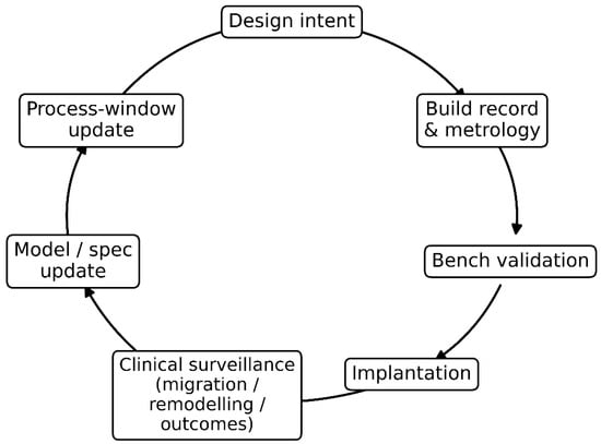
Figure 3.
Clinical-to-manufacture validation loop (“digital thread”) for mechanical compatibility. The diagram shows a closed-loop pathway linking design intent to build records and metrology, bench validation, and implantation, followed by clinical surveillance (migration, remodelling, outcomes). These clinical signals drive model/specification updates, which in turn trigger process-window updates, closing the loop by refining design and manufacturing controls to improve interface performance and long-term implant success.
8.5. Equity and Heterogeneity: Compatibility for Diverse Bodies
Finally, mechanical compatibility has an equity dimension. Tissue mechanics vary with age, sex, disease burden, and environment. Designs tuned to “average” tissues may systematically underperform in groups with different bone quality or soft tissue stiffness. Mechanically compatible design therefore requires inclusive datasets and modelling assumptions. The biomechanics literature, including region-specific and condition-specific tissue characterization, illustrates how sensitive mechanics can be to state and region. Implant design should adopt the same mindset: compatibility must be validated across the range of bodies that will receive the device.
9. Practical Implications and Research Agenda: What Changes if We Take the Thesis Seriously?
If mechanical compatibility is elevated to first-class status, several practical changes follow.
First, design input documents must explicitly contain mechanical-compatibility targets. Instead of listing only material choice and strength requirements, they should include acceptable ranges for remodelling indices, micromotion under specified loads, wear rates, and mechanosensory stiffness at the surface.
Second, manufacturing change control becomes more stringent. A change in additive manufacturing scan strategy, powder supplier, or post-processing could alter the roughness and fatigue and thus compatibility; these changes should trigger the re-verification of compatibility metrics. The observation that additively manufactured porous titanium structures retain adhered powder particles and that dimensional accuracy depends on build direction implies that manufacturing variation can directly affect interface behaviour [5].
Third, research should focus on compatibility maps rather than isolated optimisations. For porous structures, we need coupled maps of pore size, porosity, unit cell geometry, and surface finishing against both mechanical stiffness/strength and biological integration endpoints. The study by [64] suggests that within a pore size range of 400–700 μm, cell biological responses may be relatively robust while stiffness varies widely, implying that mechanical tuning can be prioritised within certain biological-safe ranges. More work is needed to map outside these ranges, to consider different cell types and loading regimes, and to incorporate fatigue and wear.
Fourth, soft tissue device design should incorporate mechanosensory biology. The TRPV4 stiffness-dependent FBR suggests that tuning stiffness may be a direct pathway to reducing capsule formation [21]. Research should identify stiffness ranges and surface compliance strategies that minimise fibrotic pathways in specific anatomical contexts.
Fifth, standards development should extend to interface mechanics. Today, many mechanical tests focus on component strength and wear rather than interface performance envelopes. Developing consensus on how to measure and specify micromotion, effective stiffness gradients, and mechanosensory stiffness would enable mechanical compatibility to become a standardised design output. Regulatory frameworks already support risk-based evaluation; the missing component is a widely accepted set of mechanical interface metrics linked to biological outcomes [10].
Finally, education and institutional practice must shift. “Biocompatibility” courses and checklists should include mechanobiological pathways and interface mechanics. Multidisciplinary teams should include manufacturing engineers and metrologists early in design, because process windows are not an afterthought; they are the means of achieving compatibility.
In short, taking the thesis seriously changes how we frame the problem: from selecting a biocompatible material to engineering a reproducible mechanobiological interface.
Short Case Studies: How “Mechanically Compatible” Thinking Changes Design Choices
Hip stems and proximal femoral remodelling provide a canonical example. Traditional stems optimised for strength and fixation often used stiff alloys and geometries that inadvertently reduced proximal strain, producing resorption patterns that were later described as stress shielding. Remodelling simulations and comparative analyses indicate that reducing stem stiffness can reduce predicted bone loss, but the design space is constrained by interface stress and the risk of instability [6]. A compatibility-first design approach reframes the problem: the goal is not the stiffest stem that survives fatigue, but the stem whose stiffness distribution yields an acceptable remodelling index profile while maintaining micromotion within the integration envelope. Achieving this often points toward graded architectures: denser cores for fatigue resistance and porous proximal regions to tune compliance and encourage ingrowth, an idea explicitly articulated in the additive manufacturing porous titanium literature.
Porous metals such as porous tantalum illustrate another pathway. Porous tantalum trabecular-like structures have been used in revision and complex reconstruction because of their high friction and potential for bone ingrowth. Their “effective modulus” can be much lower than dense metals and closer to trabecular bone, illustrating how architecture can alter mechanical compatibility while retaining the intrinsic chemical stability of the base metal. However, porous structures also raise questions of fatigue, particle release, and variability, reinforcing the need for process windows and metrology.
Soft tissue implants and sensors expose the same principles in a different modulus regime. A sensor embedded in subcutaneous tissue may be chemically inert and pass ISO cytotoxicity tests, but if its mechanosensory stiffness is substantially higher than the surrounding tissue, it can provoke a foreign body response that forms a fibrous capsule, reducing sensor performance. Mechanistic studies show that stiffness-dependent FBR is mediated through mechanosensing pathways such as TRPV4 and is associated with increased collagen deposition and foreign body giant cell formation at stiff implants. Compatibility-first design therefore motivates strategies such as compliant encapsulation layers, hydrogel interfaces, and architectural softness at the tissue-contacting surface, even when the device core must remain stiff for electronics or structural reasons.
Finally, a compatibility-first approach changes how we interpret research in tissue mechanics. The myocardial mechanics work by [14] and the biventricular modelling by [7] are often read as contributions to cardiovascular biomechanics. In a compatibility framing, they also become methodological exemplars: they show us how to obtain high-quality mechanical data, calibrate constitutive laws, and then use models to predict how changes in loading or pathology alter stress fields. The same discipline is required to design implants whose mechanical cues remain in a safe envelope as tissues remodel and as boundary conditions change.
10. Conclusions
Mechanical compatibility is not a rhetorical replacement for biocompatibility; it is an expansion of what compatibility must mean in a mechanosensitive organism. The evidence across orthopaedics and soft tissue implantation shows that stiffness mismatch, micromotion, tribological wear, and fibrosis can defeat chemically biocompatible materials. Adaptive remodelling simulations demonstrate design conflicts between reducing stress shielding and maintaining interface integrity. Systematic evidence indicates that micromotion thresholds shape whether osseointegration or fibrous encapsulation dominates. Wear debris links mechanical abrasion to immune activation and loosening. Mechanosensing studies demonstrate that stiffness itself can drive foreign body response via TRPV4-mediated pathways.
A process view turns these insights into an actionable doctrine: measure tissue mechanics, translate them into constitutive models and interface envelopes, define mechanical-compatibility specifications, realise them through controlled process windows, and close the loop through validation and surveillance. The same scientific discipline used in advanced soft tissue mechanics, illustrated by the work of Nemavhola and Masithulela in characterising and modelling complex biological materials, can and should be applied to implant interfaces. When we treat mechanical compatibility as a first-class requirement, implant success becomes less a matter of hope, and more a matter of traceable, controllable design-to-interface engineering.
Author Contributions
Conceptualization, F.N.; Methodology, L.L. and T.P.; Software, T.P.; Validation, T.P., F.N. and L.L.; Formal analysis, F.N. and R.S.; Investigation, L.L. and R.S.; Resources, R.S., L.L., T.P. and F.N. Writing—original draft preparation, F.N., L.L., R.S. and T.P.; Writing—review and editing, F.N., T.P., L.L. and R.S.; Visualization, L.L.; Supervision, F.N. and T.P.; Project administration, L.L. All authors have read and agreed to the published version of the manuscript.
Funding
This research received no external funding.
Data Availability Statement
No new data were created or analysed in this study.
Conflicts of Interest
The authors declare no conflicts of interest.
References
- Shen, G.; Fang, F.; Kang, C. Tribological performance of bioimplants: A comprehensive review. Nanotechnol. Precis. Eng. 2018, 1, 107–122. [Google Scholar]
- Goswami, R.; Arya, R.K.; Sharma, S.; Dutta, B.; Stamov, D.R.; Zhu, X.; Rahaman, S.O. Mechanosensing by TRPV4 mediates stiffness-induced foreign body response and giant cell formation. Sci. Signal. 2021, 14, eabd4077. [Google Scholar] [CrossRef] [PubMed]
- Noskovicova, N.; Hinz, B.; Pakshir, P. Implant fibrosis and the underappreciated role of myofibroblasts in the foreign body reaction. Cells 2021, 10, 1794. [Google Scholar] [CrossRef]
- Ward, W.K. A review of the foreign-body response to subcutaneously-implanted devices: The role of macrophages and cytokines in biofouling and fibrosis. J. Diabetes Sci. Technol. 2008, 2, 768–777. [Google Scholar] [CrossRef]
- Jordan, S.W.; Fligor, J.E.; Janes, L.E.; Dumanian, G.A. Implant porosity and the foreign body response. Plast. Reconstr. Surg. 2018, 141, 103e–112e. [Google Scholar] [CrossRef]
- Kastellorizios, M.; Tipnis, N.; Burgess, D.J. Foreign body reaction to subcutaneous implants. In Immune Responses to Biosurfaces: Mechanisms and Therapeutic Interventions; Springer: Cham, Switzerland, 2015; pp. 93–108. [Google Scholar]
- Masithulela, F. Bi-ventricular finite element model of right ventricle overload in the healthy rat heart. Bio-Med. Mater. Eng. 2016, 27, 507–525. [Google Scholar] [CrossRef]
- Nemavhola, F. Fibrotic infarction on the LV free wall may alter the mechanics of healthy septal wall during passive filling. Bio-Med. Mater. Eng. 2017, 28, 579–599. [Google Scholar] [CrossRef]
- Thangaraju, P.; Varthya, S.B. ISO 10993: Biological evaluation of medical devices. In Medical Device Guidelines and Regulations Handbook; Springer International Publishing: Cham, Switzerland, 2022; pp. 163–187. [Google Scholar]
- ANSI/AAMI/ISO 10993-1: 2018; Biological Evaluation of Medical Devices—Part 1: Evaluation and Testing Within a Risk Management Process. AAMI: Arlington, VA, USA, 2020.
- Weinans, H.; Huiskes, R.; Grootenboer, H.J. Effects of material properties of femoral hip components on bone remodeling. J. Orthop. Res. 1992, 10, 845–853. [Google Scholar] [CrossRef] [PubMed]
- Nemavhola, F. Study of biaxial mechanical properties of the passive pig heart: Material characterisation and categorisation of regional differences. Int. J. Mech. Mater. Eng. 2021, 16, 6. [Google Scholar] [CrossRef]
- Nemavhola, F.; Ngwangwa, H.; Davies, N.; Franz, T. Passive biaxial tensile dataset of three main rat heart myocardia: Left ventricle, mid-wall and right ventricle. Preprints 2021, 2021080153. [Google Scholar] [CrossRef]
- Nemavhola, F.; Pandelani, T.; Ngwangwa, H. Fitting of hyperelastic constitutive models in different sheep heart regions based on biaxial mechanical properties. bioRxiv 2021. preprint. [Google Scholar] [CrossRef]
- Al Ali, M. Advanced Techniques in Porous Structure Design for Additive Manufacturing; John Wiley & Sons: Hoboken, NJ, USA, 2025. [Google Scholar]
- Ferraris, S.; Spriano, S. Porous titanium by additive manufacturing: A focus on surfaces for bone integration. Metals 2021, 11, 1343. [Google Scholar] [CrossRef]
- Yousefi, M. The Role of Post Surface Finishing on the Surface Quality and Fatigue Behavior of Ti–6Al–4V Alloy Produced via Laser Powder Bed Fusion Additive Manufacturing Process. Master’s Thesis, Politecnico di Torino, Torino, Italy, 2024. [Google Scholar]
- Dziaduszewska, M.; Zieliński, A. Structural and material determinants influencing the behavior of porous Ti and its alloys made by additive manufacturing techniques for biomedical applications. Materials 2021, 14, 712. [Google Scholar] [CrossRef]
- Joshi, M.G.; Advani, S.G.; Miller, F.; Santare, M.H. Analysis of a femoral hip prosthesis designed to reduce stress shielding. J. Biomech. 2000, 33, 1655–1662. [Google Scholar] [CrossRef]
- Diegel, P.D.; Daniels, A.U.; Dunn, H.K. Initial effect of collarless stem stiffness on femoral bone strain. J. Arthroplast. 1989, 4, 173–178. [Google Scholar] [CrossRef] [PubMed]
- Naghavi, S.A.; Lin, C.; Sun, C.; Tamaddon, M.; Basiouny, M.; Garcia-Souto, P.; Taylor, S.; Hua, J.; Li, D.; Wang, L.; et al. Stress Shielding and Bone Resorption of Press-Fit Polyether–Ether–Ketone (PEEK) Hip Prosthesis: A Sawbone Model Study. Polymers 2022, 14, 4600. [Google Scholar] [CrossRef]
- Østbyhaug, P.O.; Klaksvik, J.; Romundstad, P.; Aamodt, A. Primary stability of custom and anatomical uncemented femoral stems: A method for three-dimensional in vitro measurement of implant stability. Clin. Biomech. 2010, 25, 318–324. [Google Scholar] [CrossRef]
- Hussein, M.A.; Mohammed, A.S.; Al-Aqeeli, N. Wear characteristics of metallic biomaterials: A review. Materials 2015, 8, 2749–2768. [Google Scholar] [CrossRef]
- Shen, G.; Zhang, J.; Kang, C.; Fang, F. Study on surface texture patterns for improving tribological performance of bioimplants. Surf. Coat. Technol. 2021, 422, 127567. [Google Scholar] [CrossRef]
- Martinez Marquez, D. Quality by Design for the Development of Additively Manufactured Patient-Specific Bone Implants and Scaffolds. Ph.D. Thesis, Griffith University, Brisbane, Australia, 2020. [Google Scholar]
- Pazhamannil, R.V.; Alkhedher, M. Advances in additive manufacturing for bone tissue engineering: Materials, design strategies, and applications. Biomed. Mater. 2024, 20, 012002. [Google Scholar] [CrossRef] [PubMed]
- Sebastiani, S.; Buccino, F.; Qin, Z.; Vergani, L.M. Structural influences on bone tissue engineering: A review and perspective. Matter 2025, 8, 102252. [Google Scholar] [CrossRef]
- Gürkan, D.; Sagbas, B. Ti6Al4V 3D-Printed Lattice Structures for Biomedical Applications. In Advanced Technologies for Sustainable Biomedical Applications; CRC Press: Boca Raton, FL, USA, 2025; pp. 359–403. [Google Scholar]
- Zaharin, H.A.; Abdul Rani, A.M.; Azam, F.I.; Ginta, T.L.; Sallih, N.; Ahmad, A.; Yunus, N.A.; Zulkifli, T.Z.A. Effect of unit cell type and pore size on porosity and mechanical behavior of additively manufactured Ti6Al4V scaffolds. Materials 2018, 11, 2402. [Google Scholar] [CrossRef]
- Soro, N.; Attar, H.; Wu, X.; Dargusch, M.S. Investigation of the structure and mechanical properties of additively manufactured Ti–6Al–4V biomedical scaffolds designed with a Schwartz primitive unit-cell. Mater. Sci. Eng. A 2019, 745, 195–202. [Google Scholar] [CrossRef]
- Davoodi, E.; Montazerian, H.; Mirhakimi, A.S.; Zhianmanesh, M.; Ibhadode, O.; Shahabad, S.I.; Esmaeilizadeh, R.; Sarikhani, E.; Toorandaz, S.; Sarabi, S.A.; et al. Additively manufactured metallic biomaterials. Bioact. Mater. 2022, 15, 214–249. [Google Scholar] [CrossRef]
- du Plessis, A.; Razavi, N.; Benedetti, M.; Murchio, S.; Leary, M.; Watson, M.; Bhate, D.; Berto, F. Properties and applications of additively manufactured metallic cellular materials: A review. Prog. Mater. Sci. 2022, 125, 100918. [Google Scholar] [CrossRef]
- Ziaie, B.; Velay, X.; Saleem, W. Advanced porous hip implants: A comprehensive review. Heliyon 2024, 10, e37818. [Google Scholar] [CrossRef] [PubMed]
- Chang, J.Z.; Hsu, J.T.; Li, M.J.; Lin, H.Y.; Sun, J.; Tsou, N.T.; Sun, J.S. Optimizing dental implant design: Structure, strength, and bone ingrowth. J. Dent. Sci. 2025, 20, 1016–1026. [Google Scholar] [CrossRef] [PubMed]
- Lebea, L.; Desai, D.; Ngwangwa, H.; Nemavhola, F. Influence of material orientation, loading angle, and single-shot repetition of laser shock peening on surface roughness properties. Front. Manuf. Technol. 2024, 4, 1421589. [Google Scholar] [CrossRef]
- Lebea, L.; Ngwangwa, H.; Desai, D.; Nemavhola, F. Corrosion Resistance of 3D-Printed Titanium Alloy Ti64-ELI Parts for Dental Application. Appl. Bionics Biomech. 2022, 2022, 1804417. [Google Scholar] [CrossRef]
- Lebea, L.; Ngwangwa, H.; Pandelani, T.; Nemavhola, F. Biomechanical behaviour and hyperelastic model parameters identification of sheep omasum. Res. Sq. 2021. preprint. [Google Scholar] [CrossRef]
- Lebea, L.; Ngwangwa, H.M.; Desai, D.; Nemavhola, F. Experimental investigation into the effect of surface roughness and mechanical properties of 3D-printed titanium Ti-64 ELI after heat treatment. Int. J. Mech. Mater. Eng. 2021, 16, 16. [Google Scholar] [CrossRef]
- da Silva Brum, I.; Elias, C.N.; Lopes, J.C.A.; Frigo, L.; dos Santos, P.G.P.; de Carvalho, J.J. Clinical Analysis of the Influence of Surface Roughness in the Primary Stability and Osseointegration of Dental Implants: Study in Humans. Coatings 2024, 14, 951. [Google Scholar] [CrossRef]
- Moghadasi, K.; Mohd Isa, M.S.; Ariffin, M.A.; Mohd jamil, M.Z.; Raja, S.; Wu, B.; Yamani, M.; Bin Muhamad, M.R.; Yusof, F.; Jamaludin, M.F.; et al. A review on biomedical implant materials and the effect of friction stir based techniques on their mechanical and tribological properties. J. Mater. Res. Technol. 2022, 17, 1054–1121. [Google Scholar] [CrossRef]
- Gittens, R.A.; Olivares-Navarrete, R.; Schwartz, Z.; Boyan, B.D. Implant osseointegration and the role of microroughness and nanostructures: Lessons for spine implants. Acta Biomater. 2014, 10, 3363–3371. [Google Scholar] [CrossRef] [PubMed]
- Romero-Serrano, M.; Romero-Ruiz, M.-M.; Herrero-Climent, M.; Rios-Carrasco, B.; Gil-Mur, J. Correlation between Implant Surface Roughness and Implant Stability: A Systematic Review. Dent. J. 2024, 12, 276. [Google Scholar] [CrossRef] [PubMed]
- Kjaer, M.; Langberg, H.; Heinemeier, K.; Bayer, M.L.; Hansen, M.; Holm, L.; Doessing, S.; Kongsgaard, M.; Krogsgaard, M.R.; Magnusson, S.P. From mechanical loading to collagen synthesis, structural changes and function in human tendon. Scand. J. Med. Sci. Sports 2009, 19, 500–510. [Google Scholar] [CrossRef]
- Babaniamansour, P.; Jacho, D.; Niedzielski, S.; Rabino, A.; Garcia-Mata, R.; Yildirim-Ayan, E. Modulating TRPV4 Channel Activity in Pro-Inflammatory Macrophages Within the 3D Tissue Analog. Biomedicines 2024, 12, 230. [Google Scholar] [CrossRef]
- Bliah, O.; Hegde, C.; Tan, J.M.R.; Magdassi, S. Fabrication of Soft Robotics by Additive Manufacturing: From Materials to Applications. Chem. Rev. 2025, 125, 7275–7320. [Google Scholar] [CrossRef]
- Klenam, D.E.P.; McBagonluri, F.; Asumadu, T.K.; Osafo, S.A.; Bodunrin, M.O.; Agyepong, L.; Osei, E.D.; Mornah, D.; Soboyejo, W.O. Additive manufacturing: Shaping the future of the manufacturing industry—Overview of trends, challenges and opportunities. Appl. Eng. Sci. 2025, 22, 100224. [Google Scholar] [CrossRef]
- Dipta, S.D.; Rahman, M.M.; Ansari, M.J.; Uddin, M.N. A Comprehensive Review of Sustainable and Green Additive Manufacturing: Technologies, Practices, and Future Directions. J. Manuf. Mater. Process. 2025, 9, 269. [Google Scholar] [CrossRef]
- Yu, K.; Yao, Y.; Zhang, W.; Lu, L.; Gao, Q.; Zhang, P.; Sing, S.L. Defects, monitoring, and AI-enabled control in soft material additive manufacturing: A review. Virtual Phys. Prototyp. 2025, 20, e2588456. [Google Scholar] [CrossRef]
- Brown, C.U.; Brown, C.U.; Jacob, G.; Possolo, A.; Beauchamp, C.; Peltz, M.; Stoudt, M.; Donmez, A. The Effects of Laser Powder Bed Fusion Process Parameters on Material Hardness and Density for Nickel Alloy 625; US Department of Commerce, National Institute of Standards and Technology: Gaithersburg, MD, USA, 2018. [Google Scholar]
- Paraschiv, A.; Matache, G.; Condruz, M.R.; Frigioescu, T.F.; Pambaguian, L. Laser powder bed fusion process parameters’ optimization for fabrication of dense IN 625. Materials 2022, 15, 5777. [Google Scholar] [CrossRef]
- Criales, L.E.; Arısoy, Y.M.; Lane, B.; Moylan, S.; Donmez, A.; Özel, T. Laser powder bed fusion of nickel alloy 625: Experimental investigations of effects of process parameters on melt pool size and shape with spatter analysis. Int. J. Mach. Tools Manuf. 2017, 121, 22–36. [Google Scholar] [CrossRef]
- Diaz, J.C.; Watanabe, K.; Rubio, A.; De La Cruz, A.; Godinez, D.; Nabil, S.T.; Murr, L.E.; Wicker, R.B.; Arrieta, E.; Medina, F. Effect of layer thickness and heat treatment on microstructure and mechanical properties of alloy 625 manufactured by electron beam powder bed fusion. Materials 2022, 15, 7767. [Google Scholar] [CrossRef] [PubMed]
- Shrestha, S.; Chou, K. Formation of keyhole and lack of fusion pores during the laser powder bed fusion process. Manuf. Lett. 2022, 32, 19–23. [Google Scholar] [CrossRef]
- Huang, Y.; Fleming, T.G.; Clark, S.J.; Marussi, S.; Fezzaa, K.; Thiyagalingam, J.; Leung, C.L.A.; Lee, P.D. Keyhole fluctuation and pore formation mechanisms during laser powder bed fusion additive manufacturing. Nat. Commun. 2022, 13, 1170. [Google Scholar] [CrossRef]
- Guo, L.; Wang, H.; Liu, H.; Huang, Y.; Wei, Q.; Leung, C.L.A.; Wu, Y.; Wang, H. Understanding keyhole induced-porosities in laser powder bed fusion of aluminum and elimination strategy. Int. J. Mach. Tools Manuf. 2023, 184, 103977. [Google Scholar] [CrossRef]
- Le Roux, S.; Salem, M.; Shabbar, M.; Vicharapu, B.; Muthu, N.; Moussaoui, K.; Hor, A.; Velay, V. Effect of process parameters on surface integrity in laser powder bed fusion of Ti–6Al–4V alloy. Sci. Rep. 2025, 15, 43786. [Google Scholar] [CrossRef]
- Ramirez, B.; Banuelos, C.; De La Cruz, A.; Nabil, S.T.; Arrieta, E.; Murr, L.E.; Wicker, R.B.; Medina, F. Effects of Process Parameters and Process Defects on the Flexural Fatigue Life of Ti–6Al–4V Fabricated by Laser Powder Bed Fusion. Materials 2024, 17, 4548. [Google Scholar] [CrossRef]
- Bonneric, M.; Saintier, N.; El Khoukhi, D.; Bega, J. Influence of the defect size, type, and position on the High Cycle Fatigue behavior of Ti–6Al–4V processed by laser powder bed fusion. Int. J. Fatigue 2025, 193, 108783. [Google Scholar] [CrossRef]
- Aliyu, A.A.A.; Puncreobutr, C.; Shinjo, J.; Kuimalee, S.; Phetrattanarangsi, T.; Boonchuduang, T.; Taweekitikul, P.; Panwisawas, C.; Li, W.; Poungsiri, K. Lack of fusion-induced cracking effect on tensile and fatigue behaviours of laser powder-bed fusion-processed Ti–6Al–4V implant. Eng. Fail. Anal. 2025, 168, 109095. [Google Scholar] [CrossRef]
- Schulz, J.E.G.; Costa Santos, E.; Bruder, E.; Bollin, S.; Durst, K. Fatigue Performance of Additively Manufactured Ti–6Al–4V: Impact of Different Kinds of Porosities, Surface, and Heat Treatments in Laser Powder Bed Fusion Productivity Parameters. Adv. Eng. Mater. 2025, 27, e202500854. [Google Scholar] [CrossRef]
- Cao, S.; Zou, Y.; Lim, C.V.S.; Wu, X. Review of laser powder bed fusion (LPBF) fabricated Ti–6Al–4V: Process, post-process treatment, microstructure, and property. Light Adv. Manuf. 2021, 2, 313–332. [Google Scholar] [CrossRef]
- Baskin, N.; Yuce, C. Effect of process parameters on the mechanical behavior of Ti6Al4V alloys fabricated by laser powder bed fusion method. J. Mater. Res. Technol. 2024, 30, 7006–7019. [Google Scholar] [CrossRef]
- Chen, Z.; Wu, X.; Davies, C.H. Process variation in laser powder bed fusion of Ti–6Al–4V. Addit. Manuf. 2021, 41, 101987. [Google Scholar] [CrossRef]
- Bayrak, T.; Çopur, F.Ö. Evaluation of the unique device identification system and an approach for medical device tracking. Health Policy Technol. 2017, 6, 234–241. [Google Scholar] [CrossRef]
- Kärrholm, J. Radiostereometric analysis of early implant migration—A valuable tool to ensure proper introduction of new implants. Acta Orthop. 2012, 83, 551–552. [Google Scholar] [CrossRef] [PubMed]
- Kaptein, B.L.; Pijls, B.; Koster, L.; Kärrholm, J.; Hull, M.; Niesen, A.; Heesterbeek, P.; Callary, S.; Teeter, M.; Gascoyne, T.; et al. Guideline for RSA and CT-RSA implant migration measurements: An update of standardizations and recommendations. Acta Orthop. 2024, 95, 256–267. [Google Scholar] [CrossRef]
- Drozda, J.P., Jr.; Roach, J.; Forsyth, T.; Helmering, P.; Dummitt, B.; Tcheng, J.E. Constructing the informatics and information technology foundations of a medical device evaluation system: A report from the FDA unique device identifier demonstration. J. Am. Med. Inform. Assoc. 2018, 25, 111–120. [Google Scholar] [CrossRef]
- Katsoulakis, E.; Wang, Q.; Wu, H.; Shahriyari, L.; Fletcher, R.; Liu, J.; Achenie, L.; Liu, H.; Jackson, P.; Xiao, Y.; et al. Digital twins for health: A scoping review. npj Digit. Med. 2024, 7, 77. [Google Scholar] [CrossRef]


Disclaimer/Publisher’s Note: The statements, opinions and data contained in all publications are solely those of the individual author(s) and contributor(s) and not of MDPI and/or the editor(s). MDPI and/or the editor(s) disclaim responsibility for any injury to people or property resulting from any ideas, methods, instructions or products referred to in the content. |
© 2026 by the authors. Licensee MDPI, Basel, Switzerland. This article is an open access article distributed under the terms and conditions of the Creative Commons Attribution (CC BY) license.